Table of Contents
Advertisement
Quick Links
Advertisement
Table of Contents

Related Manuals for Mitsubishi Electric Apricot


Summary of Contents for Mitsubishi Electric Apricot
- Page 1 OWNER’S HANDBOOK Shogun apricot MITSUBISHI ELECTRIC...
- Page 2 OWNER’S HANDBOOK...
- Page 3 Information contained in this document is subject to change without notice and does not represent a commitment on the part of Apricot Computers Limited. Any software described in this manual is furnished under a license agreement. The software may be used or copied only in accordance with the terms of this agreement.
- Page 4 S a f e t y a n d R e g u l a t o r y N o t i c e s Safety and Regulatory Notices Read the separate Power Connection Guide before using the computer for the first time.
- Page 5 S a f e t y a n d R e g u l a t o r y N o t i c e s Power cord requirements The power cord packed with the computer complies with the safety standards applicable in the country in which it is first sold.
- Page 6 S a f e t y a n d R e g u l a t o r y N o t i c e s UK plug wiring instructions The wire which is coloured green-and- IMPORTANT: yellow must be connected to the terminal in the plug which is marked with Power Cable the letter E, or by the earth symbol...
-
Page 7: Radio And Television Interference
S a f e t y a n d R e g u l a t o r y N o t i c e s Refer to the labels on the rear of the computer to establish which of the following warnings apply. -
Page 8: Table Of Contents
CONTENTS Introduction System Overview and Features Structure of the Owner’s Handbook Operating Your System Front View Rear Panel Machine Interior Setting Up Your System for the First Time Using the Front Panel Security 2/11 Automatic Failure Recovery 2/12 Using the System Configuration Utility 2/12 The Flash Memory 2/17... - Page 9 C o n t e n t s System Management Controller Board 4/25 Cooling Fan and Handguard 4/30 Hard Disk Drive Cooling Fan Assembly 4/32 Hard Disk Drive Module Backplane 4/36 Motherboard Power Distribution Panel 4/39 Motherboard 4/41 Motherboard Cooling Fan Assembly 4/47 Hard Disk Drive Power Distribution Panel 4/49...
-
Page 10: Introduction
Owner’s Handbook is organized. System Overview and Features Your Apricot is a fully symmetrical multiprocessor system that can be expanded and adapted according to your needs. The system will support: ♦ One to four 100-MHz Pentium processors, via single or dual processor cards. - Page 11 I n t r o d u c t i o n Other features include: ♦ Multi-processor Bus. The system is equipped with a chipset that controls a multiplexed 64-bit bus and achieves a peak transfer rate of 267 Mbytes per second at 33 MHz. It also provides an integrated 1.2 Mbyte cache and an intelligent PCI bridge.
-
Page 12: Structure Of The Owner's Handbook
I n t r o d u c t i o n Structure of the Owner’s Handbook The information in the Owner’s Handbook is divided into the following parts: Operating Your System - This section explains the use of the Front Panel Controls. -
Page 13: Operating Your System
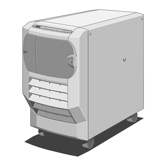
OPERATING YOUR SYSTEM This section identifies the different parts of your system, explains what you should do when using the system for the first time and shows you how to carry out tasks which are part of normal operation. Front View The following illustration shows a front view of the server with the drive bay door open: COMPA... - Page 14 O p e r a t i n g Y o u r S y s t e m The following paragraphs explain each item on the front of the machine: ♦ Diagnostic Codes LCD - Displays diagnostic codes that indicate errors or normal stages in the boot process (see the separate document Diagnostic Codes Reference Guide).
-
Page 15: Rear Panel
O p e r a t i n g Y o u r S y s t e m Rear Panel The rear panel contains the various ports and connectors as shown in the following illustration: Figure 2-2 Rear Panel Keyboard Connector (PS/2) Expansion Slot Openings Mouse Connector (PS/2) -
Page 16: Machine Interior
O p e r a t i n g Y o u r S y s t e m Machine Interior The interior of the server consists of the following main areas: ♦ Hard Disk Subsystem ♦ Removable Media Drive Bay ♦... - Page 17 O p e r a t i n g Y o u r S y s t e m Removable Media Drive Bay The removable media drive bay is the area which contains drives such as floppy, CD ROM and tape backup. The bay will accommodate up to four half-height 5.25-inch drives.
- Page 18 The Event Manager User’s Guide contains more details about this feature. Cooling Fans Your Apricot is equipped with six large cooling fans, three on each side of the machine. These will prevent overheating by maintaining an appropriate temperature inside the system.
-
Page 19: Setting Up Your System For The First Time
O p e r a t i n g Y o u r S y s t e m Setting Up Your System for the First Time After you have unpacked the server, rolled it into position and used the jacking mechanism on the front castors to immobilize it (see the separate document Getting Started), use the following steps to set up the system: Connect the monitor, keyboard, mouse and mains power cables to... -
Page 20: Using The Front Panel
O p e r a t i n g Y o u r S y s t e m Using the Front Panel This section describes the functions of the front panel during normal operation. Note Do not place any weight, either by leaning or by placing objects, on the fascia surrounding the front panel. - Page 21 O p e r a t i n g Y o u r S y s t e m number for each of the SCSI devices installed in your system. What happens after this depends on how your Apricot has been configured, i.e. which operating system or other software may be installed.
- Page 22 O p e r a t i n g Y o u r S y s t e m Special Button Functions Caution Do not use these functions unless there is serious problem with the system and it is absolutely necessary. Pressing S and R simultaneously while the front...
-
Page 23: Security
♦ Steady green means that the system is on. Security Your Apricot is equipped with a security system to help prevent unauthorized persons tampering with the front panel buttons and gaining access to the interior of the system. Security is enabled within the System Management Application (see the SMA User’s Guide, the Event Manager User’s Guide or the on-line help within... -
Page 24: Automatic Failure Recovery
O p e r a t i n g Y o u r S y s t e m Automatic Failure Recovery As with any computer system, your server may develop a hardware or software fault, which, for example, may only manifest itself intermittently, that causes the system to hang. - Page 25 O p e r a t i n g Y o u r S y s t e m To run the SCU: Locally, press F2 to run the Flash Disk Utility during the hardware boot sequence but before the operating system loads; remotely, run the Flash Disk Utility via the SMA.
- Page 26 O p e r a t i n g Y o u r S y s t e m How to use the SCU The Help text will provide most of the instructions you will need to use the SCU. The following paragraphs briefly explain the general techniques for navigating your way through the utility.
- Page 27 O p e r a t i n g Y o u r S y s t e m How to use SCU Help There are two ways to access SCU Help: ♦ Select Step 1: About System Configuration, from the Main Menu.
- Page 28 You will not be able to boot the system from a remote workstation. Password Clear Switch There is a Password Clear Switch on the motherboard of your Apricot. If you set this switch to On, the passwords will be cleared (i.e. removed) every time you boot or reset the system.
-
Page 29: The Flash Memory
O p e r a t i n g Y o u r S y s t e m The Flash Memory The Flash is a special portion of read-only memory (ROM). It differs from conventional ROM in that its contents can be updated, but it still preserves its information when system power is off. - Page 30 O p e r a t i n g Y o u r S y s t e m ♦ Option 4, Upgrade Motherboard BIOS - This option enables you to upgrade the motherboard’s BIOS with a new version of BIOS information.
-
Page 31: Upgrading Your System
UPGRADING YOUR SYSTEM This chapter explains how to add the following items to your system: ♦ Processor, memory or expansion cards. ♦ Memory modules to an existing memory card. ♦ Additional hard disks. Important Note Only authorized engineers may have access to the electronics chamber of the server, on the opposite side from the hard disk chamber. - Page 32 U p g r a d i n g Y o u r S y s t e m To remove the side panel: Switch the machine to Standby mode. Note If you are just going to add or hot-swap a hard disk drive, you can do it while the machine is still switched on.
- Page 33 U p g r a d i n g Y o u r S y s t e m Refitting the Side Panel Use the following steps to refit the side panel: Ensure that the lip on the inner surface of the side panel fits over the chassis ridge.
- Page 34 U p g r a d i n g Y o u r S y s t e m Installing CPU and Memory Cards Important Note The procedures explained in this section are for authorized engineers only. There are four slots reserved for memory and CPU cards. They are located on the motherboard towards the top of the electronics chamber.
- Page 35 U p g r a d i n g Y o u r S y s t e m The following diagram shows the positions of the slots: Figure 3-4 Memory and CPU slots Memory Slot 1 CPU Slot 1 Memory Slot 2 CPU Slot 2 Note...
- Page 36 U p g r a d i n g Y o u r S y s t e m You can fit either one or two of both kinds of cards. The CPU card can contain either single or dual processors and can be fitted in the following configurations: ♦...
-
Page 37: Upgrading Memory
Important Note The procedure explained in this section is for authorized engineers only. The maximum memory capacity of your Apricot is 768 Mbytes, provided by up to two ECC memory cards. Each memory card contains twelve 36-bit SIMM (Single Inline Memory Module) slots. - Page 38 Inserting SIMMs Important Fit only correct Apricot-approved SIMMS into your server. For each socket in the bank: The SIMM will only install in one orientation. There is a cutout at one end of the SIMM next to the connector strip.
- Page 39 U p g r a d i n g Y o u r S y s t e m Figure 3-6 Positioning the SIMM Lower the SIMM into the socket and ensure that it is properly seated. Pushing gently on the top corners, rotate the SIMM towards the vertical.
-
Page 40: Installing And Removing Expansion Cards
U p g r a d i n g Y o u r S y s t e m Installing and Removing Expansion Cards Important Note The procedures explained in this section are for authorized engineers only. The following illustration shows the positions of the expansion card slots in the electronics chamber: Figure 3-8 PCI and EISA/ISA Expansion Card Slots PCI Slots... - Page 41 U p g r a d i n g Y o u r S y s t e m Installing Study the expansion board’s installation guide and follow its directions. The guide should tell you what kind of slot (i.e. PCI or EISA/ISA) you will use and whether there are any jumpers or switches on the card that you need to configure.
-
Page 42: Fitting Hard Disk Drives
U p g r a d i n g Y o u r S y s t e m Removing Unplug all cables connected to the board. Remove the securing screw and pull the board out of the slot, leaving an empty space on the rear panel for the blanking plate again. - Page 43 U p g r a d i n g Y o u r S y s t e m Fitting a Hard Disk Drive There can be up to five drive modules in the subsystem, each containing up to four drives. Each drive is fastened onto a removable drive tray. To fit a drive: Locate an empty drive tray.
- Page 44 U p g r a d i n g Y o u r S y s t e m Turn the hard disk tray release handle anti-clockwise until it stops, which is almost one complete turn. As you turn the handle, the drive tray ejects slightly.
- Page 45 Note Since the hard disk drives for your Apricot are exclusively SCSI drives, it is important to note that the SCSI connector on the inside of the drive module backplane contains the device address. This means that, for a given connector, any disk drive that is fitted to that connector will have the same SCSI address.
-
Page 46: Service Information
Uninterruptible Power Supply Unit ♦ UPS Battery Pack Your Apricot has been designed so that in most cases you can remove a component without disturbing adjacent items. The procedures for removing or fitting CPU cards, memory cards and other expansion cards are not presented in this chapter. For these, refer to Chapter 3, Upgrading Your System. -
Page 47: Preliminary Service Tasks
S e r v i c e I n f o r m a t i o n Preliminary Service Tasks Before you can perform a service procedure, you must do the following: Refer to the SMA and note down the value of the TimeOnCharge variable. -
Page 48: Hard Disk Drive
S e r v i c e I n f o r m a t i o n Hard Disk Drive Your Apricot is equipped with SCSI hard disk drives which are hot pluggable, i.e. you can remove or fit them while the system is powered up. - Page 49 S e r v i c e I n f o r m a t i o n Figure 4-2 Hard Disk Tray Removal Slide the tray out carefully until it is free of the chassis. Turn the tray over and remove the four securing screws on the underside.
- Page 50 S e r v i c e I n f o r m a t i o n Fitting Locate an empty drive tray. It may be wise to keep a written record of which trays are fitted with drives. You can identify a specific drive by observing the labelling scheme as shown in the following illustration: Figure 4-4 Disk Subsystem Labelling Scheme...
- Page 51 Note Since the hard disk drives for your Apricot are exclusively SCSI drives, it is important to note that the SCSI connector on the backplane of the drive module contains the device address. This means that, for a given connector, any disk drive that is fitted to that connector will have the same SCSI address.
-
Page 52: Hard Disk Drive Module
S e r v i c e I n f o r m a t i o n Hard Disk Drive Module The hard disk drive module is the removable metal framework which holds up to four hard disk drives. The server’s disk subsystem can accommodate up to five of these modules. - Page 53 S e r v i c e I n f o r m a t i o n Note One of the connectors, located underneath the cooling fan assembly, is considerably less accessible than the others. If it is too difficult to unplug this connector in the electronics chamber, carry out steps 3 and 4, remembering to feed the ribbon cable carefully through the centre spine opening.
- Page 54 S e r v i c e I n f o r m a t i o n Fitting If necessary, remove the knockout panel which covers the drive module data connector opening in the centre spine of the server. You will only need to do this the first time you fit a module in this position.
- Page 55 S e r v i c e I n f o r m a t i o n Now reach inside the module and push on the power circuit board on the backplane to ensure that its connector is seated properly into the power socket on the centre spine.
- Page 56 S e r v i c e I n f o r m a t i o n Now use the four screws to fasten the module to the subsystem metalwork. Figure 4-10 Fitting Drive Module Empty Disk Drive Module Securing Screws OWNER’S HANDBOOK 4-11...
- Page 57 S e r v i c e I n f o r m a t i o n In the electronics chamber, plug the appropriate ribbon cable onto the data connector on the backplane of the drive module: Figure 4-11 Plugging Ribbon Cable to Module Data Connector Hard Disk Module Data Ribbon Cable Connector...
-
Page 58: Front Bezel
S e r v i c e I n f o r m a t i o n Front Bezel Removing Ensure that the removable media drive bay door is close and locked. SH-18 On each side of the server, remove the protective metal plates which cover the removable media drives and the electronics chamber. - Page 59 S e r v i c e I n f o r m a t i o n Reach behind the bezel and disconnect the ribbon cable from the front panel. Fitting Ensure that the hard disk drive module closest to the front of the machine (module 1) is removed.
-
Page 60: Front Panel
S e r v i c e I n f o r m a t i o n Front Panel Removing With the front bezel removed and the ribbon cable disconnected from the front panel, remove the circlip from the top hinge of the removable media drive bay door (which should be closed and locked). - Page 61 S e r v i c e I n f o r m a t i o n Gently press down on the metal plate to detach it from the hinge as shown: Figure 4-15 Detaching the Hinge Metal Plate Hinge Now remove the two screws as shown: Figure 4-16 Removing Front Panel Supporting Metalwork...
- Page 62 S e r v i c e I n f o r m a t i o n Remove the eight screws which fasten the front panel onto the metalwork: Figure 4-17 Front Panel Securing Screws Front Panel Metal Protrusion Holes Securing Screws Remove the front panel.
- Page 63 S e r v i c e I n f o r m a t i o n Fitting Attach the front panel to the supporting metalwork by means of the eight screws as shown: Figure 4-18 Front Panel Securing Screws Front Panel Metal Protrusion Holes Securing Screws...
- Page 64 S e r v i c e I n f o r m a t i o n Insert the front panel framework into the bezel as shown: Figure 4-19 Fitting Front Panel Supporting Metalwork Front Panel Supporting Securing Screws Metalwork Fasten the framework onto the bezel using the two screws.
-
Page 65: Removable Media Drives
S e r v i c e I n f o r m a t i o n Removable Media Drives To gain access to the removable media drives and the System Management Controller (SMC) you must first remove the protective metal plate which covers this area. - Page 66 S e r v i c e I n f o r m a t i o n Removing Each drive is attached to a drive tray, which is in turn secured to a drive cage. To remove a tray from the cage: Unplug the data and power cables from the rear of the drive.
- Page 67 S e r v i c e I n f o r m a t i o n Turn the tray over and remove four screws from the underside of the tray as shown: A C T C O M P Figure 4-23 Drive Tray Removal Drive Tray Securing Screws...
- Page 68 S e r v i c e I n f o r m a t i o n Fitting Your server is equipped with a tray and a blanking plate for each empty drive bay. Remove the blanking plate, if necessary, from the drive tray. The plate is attached via two screws on the underside of the tray.
- Page 69 S e r v i c e I n f o r m a t i o n Turn the drive upright, slide it into the drive cage and secure it to the cage using the two screws. The following illustration shows the securing screws for three of the drive trays: Figure 4-25 Removable Media Drive Bay (Internal) Securing Screws...
-
Page 70: System Management Controller Board
S e r v i c e I n f o r m a t i o n System Management Controller Board Although some of the board is hidden behind the cooling fan assembly, all of the fixing screws and cable connections are easily accessible. Removing Unplug three ribbon cable connectors, the power connector, three fan connectors, two thermistor connectors and one keylock sensor... - Page 71 S e r v i c e I n f o r m a t i o n Remove the two screw lock posts on the 25-way SMC serial port connector which is visible on the server’s back panel: Figure 4-27 SMC Serial Port Screw Lock Posts Screw Lock Posts Back panel Remove the seven fastening screws and lift the board out of the...
- Page 72 S e r v i c e I n f o r m a t i o n Fitting Feed the 25-way serial port connector through the opening in the back panel. Fasten the board to the centre spine using the seven screws as shown in the following illustration: Figure 4-28 System Management Controller Board Power Connector...
- Page 73 S e r v i c e I n f o r m a t i o n Against each fan connector on the board there is a graphic which indicates which fan cable should be plugged in: Middle Bottom The middle and bottom fans in this series are located below the SMC board in the disk subsystem area.
- Page 74 S e r v i c e I n f o r m a t i o n Tilt the top of the assembly slightly towards the interior of the server (if it hasn’t already) and lift it upwards to free it from the chassis.
-
Page 75: Cooling Fan And Handguard
S e r v i c e I n f o r m a t i o n Cooling Fan and Handguard These instructions apply to all the fans in the server. Removing Remove the four screws which hold the handguard onto the fan assembly housing. - Page 76 S e r v i c e I n f o r m a t i o n Fitting Caution Before attempting to fit the fan onto the fan assembly housing, be sure to place the fan into the assembly so that the air flow through it is from the front of the server to the rear (see the arrow next to the electrical polarity marking on one corner of the fan).
-
Page 77: Hard Disk Drive Cooling Fan Assembly
S e r v i c e I n f o r m a t i o n Hard Disk Drive Cooling Fan Assembly You can remove and fit the hard disk drive cooling fan assembly without disturbing the adjacent disk drive module. Removing Unplug the middle and bottom fan connectors and their associated thermistor connectors from the SMC board as shown:... - Page 78 S e r v i c e I n f o r m a t i o n Remove two screws which fasten the fan assembly to the chassis: Figure 4-33 Removing the Hard Disk Cooling Fan Assembly Securing Screws Finger Grip Use the finger grip to slide the assembly towards you.
- Page 79 S e r v i c e I n f o r m a t i o n Fitting Slide the assembly into position, remembering to feed the guide tabs into the positioning slots as shown in the following illustration: Figure 4-34 Refitting Hard Disk Cooling Fan Assembly Positioning Slots Securing Screws...
- Page 80 S e r v i c e I n f o r m a t i o n Plug the bottom and middle fan connectors, together with their associated thermistor connectors, in to the SMC board as indicated in the following diagram: Figure 4-35 SMC Fan and Thermistor Connectors for Middle and Bottom Fans Fan Connectors Thermistor Connectors...
-
Page 81: Hard Disk Drive Module Backplane
S e r v i c e I n f o r m a t i o n Hard Disk Drive Module Backplane The backplane on a hard disk drive module consists of seven small circuit boards which are fastened with screws to the metal framework and connected to each other by a flexible ribbon cable. - Page 82 S e r v i c e I n f o r m a t i o n Removing There are two fastening screws for each board except the removable media drive SCSI interface board, which has four. To remove the backplane: Remove all disk drives from the module.
- Page 83 S e r v i c e I n f o r m a t i o n Jumper Settings for the Removable Media SCSI Interface Board Each module backplane contains a removable media SCSI interface board, positioned at the top of the module. However, only one of the boards, the one in module B, is ever attached to the removable media SCSI cable.
-
Page 84: Motherboard Power Distribution Panel
S e r v i c e I n f o r m a t i o n Motherboard Power Distribution Panel The motherboard power distribution panelis fixed to the inner roof of the electronics chamber and is positioned at right angles to the motherboard. The following illustration shows the connectors and the eight securing screws on the board: Figure 4-38 Motherboard Power Distribution Panel... - Page 85 S e r v i c e I n f o r m a t i o n Fitting Fasten the panel to the inner roof of the electronics chamber with the 8 screws. Attach the two pairs of bus bars. Plug the various connectors into the board.
-
Page 86: Motherboard
S e r v i c e I n f o r m a t i o n Motherboard SH-22 Removing Unplug all cables and leads from the back panel connectors (i.e. serial, parallel, video, keyboard, mouse) on the motherboard and from any expansion cards. - Page 87 S e r v i c e I n f o r m a t i o n Rotate the right edge of the plate slightly towards you and unhook the left edge. Removing the plate uncovers the motherboard: Figure 4-40 Motherboard Floppy Disk Cable System Management Interface Card (SMIC)
- Page 88 S e r v i c e I n f o r m a t i o n Now remove the System Management Interface Card (SMIC). Unplug its ribbon cable, which is attached to the distribution board at the top of the electronics chamber, using the ejector latches: Figure 4-41 - SMIC Connector Ejector Latches Ejector Latches Connector...
- Page 89 S e r v i c e I n f o r m a t i o n 12. Now remove 14 screws which secure the board to the centre spine of the server, as shown: Figure 4-42 Motherboard Securing Screws Motherboard Securing Screws 13.
- Page 90 S e r v i c e I n f o r m a t i o n Fitting Attach the motherboard to the centre spine of the server using the 14 screws as shown in the following illustration: Figure 4-43 Motherboard Securing Screws Motherboard Securing Screws Reconnect the hard disk cables from the drive modules to the...
- Page 91 S e r v i c e I n f o r m a t i o n Plug the five DC power cables into their respective connectors on the power distribution board at the top of the electronics chamber. These connectors are keyed and cannot be plugged incorrectly.
-
Page 92: Motherboard Cooling Fan Assembly
S e r v i c e I n f o r m a t i o n Motherboard Cooling Fan Assembly Removing Remove five screws on the side of the fan assembly. Remove four more screws which fasten the assembly to the centre spine of the server, as shown: Figure 4-45 Removing Cooling Fan Assembly Side Securing Screws... - Page 93 S e r v i c e I n f o r m a t i o n Before removing the assembly entirely, unplug the ribbon cable from the connector on the small power distribution panel between the bottom and middle fans: 4-46 Connectors on Small Power Distribution Panel Ribbon Cable Connector Fan Thermistor Cables...
-
Page 94: Hard Disk Drive Power Distribution Panel
S e r v i c e I n f o r m a t i o n Hard Disk Drive Power Distribution Panel Removing Remove the motherboard cooling fan assembly. This uncovers three bus bars which are attached to the power distribution panel, through a cut-out in the centre spine, and to the power supply, as shown in the following illustration: Figure 4-47 Bus Bars Connected to Hard Disk Power Distribution Panel... - Page 95 S e r v i c e I n f o r m a t i o n Remove 11 screws as shown in the following diagram and lift out the panel. Figure 4-48 Hard Disk Power Distribution Board Power Distribution Panel Removable Media Drives Securing Screws SMC Board...
- Page 96 S e r v i c e I n f o r m a t i o n Fitting With all hard disk drives, drive modules and the motherboard cooling fan assembly removed, attach the hard disk distribution board to the centre spine of the server, in the disk chamber, using the 11 screws as shown: Figure 4-49 Hard Disk Power Distribution Board Power Distribution Panel...
- Page 97 S e r v i c e I n f o r m a t i o n In the electronics chamber, attach the three bus bars as shown: Figure 4-50 Bus Bars Connected to Hard Disk Power Distribution Panel Note You must use a torque wrench to tighten the bus bar bolts.
-
Page 98: Removable Media Drive Bay Power Distribution Panel
S e r v i c e I n f o r m a t i o n Removable Media Drive Bay Power Distribution Panel Removing In the electronics chamber, unplug two power cables as shown in SH-51 the following diagram: Figure 4-51 Removable Drive Bay Power Distribution Panel Cable Connectors Securing Screws... - Page 99 S e r v i c e I n f o r m a t i o n Fitting Fasten the power distribution panel onto the centre spine of the server with the six screws as shown: Figure 4-52 Removable Drive Bay Power Distribution Panel Cable Connectors Securing Screws Connect the two power cables as shown in the previous illustration.
-
Page 100: Loudspeaker
S e r v i c e I n f o r m a t i o n Loudspeaker Removing Remove the motherboard cooling fan assembly. Unplug the loudspeaker cable from the connector on the motherboard power distribution panel, as shown: Figure 4-53 Loudspeaker Connector Loudspeaker Connector Cooling Fan Assembly... - Page 101 S e r v i c e I n f o r m a t i o n Remove the four screws which fasten the loudspeaker onto the front drive bay door housing, as shown: Figure 4-54 Loudspeaker Loudspeaker Securing Screws Removable Media Drive Bay Thread the cable through the opening behind the cooling fan assembly and remove the loudspeaker.
- Page 102 S e r v i c e I n f o r m a t i o n Fitting Remove the motherboard cooling fan assembly. Use the four screws to attach the loudspeaker to the front drive bay door housing, as shown: Figure 4-55 Loudspeaker Loudspeaker Securing Screws Removable Media Drive Bay...
- Page 103 S e r v i c e I n f o r m a t i o n Plug the cable into the loudspeaker connector on the motherboard power distribution panel as indicated in the following illustration: Figure 4-56 Loudspeaker Connector Loudspeaker Connector Cooling Fan Assembly Power Distribution Panel...
-
Page 104: Uninterruptible Power Supply Unit
S e r v i c e I n f o r m a t i o n Uninterruptible Power Supply Unit The UPS unit consists of the actual power supply and the accompanying battery pack. The unit is very robust and is very heavy, approximately 35kg including battery pack. - Page 105 S e r v i c e I n f o r m a t i o n Removing It is vitally important to ensure that the system is shut down, the battery pack circuit breaker switch is in the Off position and the system is disconnected from the mains electricity supply.
- Page 106 S e r v i c e I n f o r m a t i o n also attached to the power distribution panel at the top of the electronics chamber. Unplug three cables, one ribbon, one 12-way and one 16-way, from the power supply as shown: Figure 4-59 Disconnecting Power Supply Cables System Controller...
- Page 107 S e r v i c e I n f o r m a t i o n Loosen four floating fasteners, two on each side of the server, until they are free of the power supply unit, as indicated in the following diagram: Figure 4-60 Power Supply Floating Fasteners Floating Fasteners...
- Page 108 S e r v i c e I n f o r m a t i o n Using the handle on the battery pack, pull the unit carefully until it is a little less than halfway out (about 30cm), just before it begins to tip towards you.
- Page 109 S e r v i c e I n f o r m a t i o n Fitting With the help of a second person on the opposite side, place your hands underneath the power supply as indicated by the arrows in the following illustration: Figure 4-63 Fitting the Power Supply Now carefully slide the unit all the way into the chassis.
- Page 110 S e r v i c e I n f o r m a t i o n Now tighten the four floating fasteners, two on each side, located towards the front of the machine: Figure 4-65 Power Supply Floating Fasteners Floating Fasteners Front Bezel OWNER’S HANDBOOK 4-65...
- Page 111 S e r v i c e I n f o r m a t i o n Plug the ribbon, 12-way and 16-way cables into their connectors on the power supply: Figure 4-66 Connecting Power Supply Cables System Controller Removable Media Drive Bay Connector (Ribbon Cable) Connector (12-way)
- Page 112 S e r v i c e I n f o r m a t i o n Attach two pairs of bus bars and fit one set of 3 bus bars as shown: Figure 4-67 - Bus Bars Motherboard Bus Bars Bus Bars for Hard Disk Power Distribution Panel As with the cables, it is not possible to fit these bars incorrectly.
-
Page 113: Ups Battery Pack
S e r v i c e I n f o r m a t i o n UPS Battery Pack The UPS is equipped with a replaceable battery pack. It will provide electric power for your system for a specific period of time, depending on how many hard disks or other devices are installed. - Page 114 S e r v i c e I n f o r m a t i o n Pull the battery pack handle carefully and slide the pack out slowly until the power connector, as shown in the following illustration, appears: Figure 4-69 Unplugging the Battery Pack Power Connector Gently pull the connector apart as indicated.
- Page 115 S e r v i c e I n f o r m a t i o n Push the pack the rest of the way into the chassis. Figure 4-71 Refitting the Battery Pack Use the screws as shown in the previous diagram to secure the battery pack.
-
Page 116: Technical Information
TECHNICAL INFORMATION This section contains technical information about your Apricot under the following topics: ♦ Functional Architecture ♦ Memory ♦ Central Processing Unit ♦ Motherboard ♦ Switches and Jumpers ♦ I/O Connectors and Headers ♦ System Management Interface Card (SMIC) ♦... -
Page 117: Functional Architecture
T e c h n i c a l I n f o r m a t i o n Functional Architecture Your server’s functional divisions consist of the following: ♦ Motherboard ♦ System Management Controller ♦ Front Panel ♦ Uninterruptible Power Supply (UPS) ♦... - Page 118 T e c h n i c a l I n f o r m a t i o n The architecture of your server supports symmetrical multiprocessing (MP) and a variety of operating systems. The server is equipped with both PCI (Peripheral Component Interconnect) and EISA (Extended Industry Standard Architecture) busses.
-
Page 119: Memory
T e c h n i c a l I n f o r m a t i o n Memory Server memory is located on one or two ECC memory module expansion cards. Fully loaded, one card provides 384 Mbytes of common high- speed memory for the server. - Page 120 T e c h n i c a l I n f o r m a t i o n Memory Map Address Range (hex) Amount Function 0000,0000 – 0003,FFFF 256 KB Base system memory (fixed) 0004,0000 – 0007,FFFF 256 KB Base system memory (fixed) 0008,0000 –...
-
Page 121: Central Processing Unit
T e c h n i c a l I n f o r m a t i o n Central Processing Unit The server’s CPU is found on an add-on CPU card and not on the motherboard. The system will accept either a single or dual processor module. - Page 122 T e c h n i c a l I n f o r m a t i o n ♦ Compatible Intel proprietary bus interface providing support for: − 64-bit data bus − Bus level symmetrical multiprocessing − 64/128-bit memory only (ECC) memory 4 × 16 −...
-
Page 123: Motherboard
T e c h n i c a l I n f o r m a t i o n Motherboard Expansion Slots EISA Slots The six EISA bus slots on the motherboard provide for expansion and performance enhancement. Two of these share a common chassis I/O expansion slot with two of the PCI slots;... - Page 124 T e c h n i c a l I n f o r m a t i o n The PCI bus provides: ♦ 32- and 64-bit memory addressing ♦ +5 V and + 3 V signalling environments ♦ Burst transfers at 133 Mbytes per second ♦...
- Page 125 T e c h n i c a l I n f o r m a t i o n output drivers can directly drive a 48 mA, single-ended SCSI bus with no additional drivers. No additional logic, termination, or resistor loads are required to connect up to seven 8-bit narrow SCSI devices or up to fifteen 16-bit wide SCSI devices to each SCSI-2 channel on the system board.
- Page 126 T e c h n i c a l I n f o r m a t i o n I/O Address(es) Resource 03BC – 03BF Parallel Port 1 (Primary) 03C0 – 03CF Enhanced Graphics Adapter 03D4 – 03DA Color Graphics Controller 03E8 –...
- Page 127 T e c h n i c a l I n f o r m a t i o n EISA Slot Assignments EISA Slot (hex) Device System board 1−8 EISA expansion boards 9−A Embedded SCSI Memory module Memory module (expansion module) Primary PCI segment CPU1 module CPU2 module...
- Page 128 T e c h n i c a l I n f o r m a t i o n COM3; if enabled, it can be set for EISA add-in boards using the SCU COM4; if enabled, it can be set for EISA add-in boards using the SCU Onboard PS/2 mouse port, if enabled Math coprocessor error...
-
Page 129: Switches And Jumpers
T e c h n i c a l I n f o r m a t i o n Switches and Jumpers SH-63 This section explains how to set the motherboard switches and jumpers for specific operating parameters. The following diagram shows the positions of the switches and jumpers and indicates their default settings: S8C1 1 2 3... - Page 130 T e c h n i c a l I n f o r m a t i o n CMOS S8C1-1 Setting this switch to ON clears CMOS and sets it and the real-time clock (RTC) to the manufacturing defaults during system reset. Setting it to OFF preserves the settings during system reset.
- Page 131 T e c h n i c a l I n f o r m a t i o n Flash Memory S8C1-3 This switch enables or disables writing to the motherboard Flash memory. To set this switch: With the side panel removed and the electronics chamber uncovered, set this switch to ON to apply +12V power to the VPP pin on the flash memory device.
- Page 132 T e c h n i c a l I n f o r m a t i o n Video Sleep Jumper J6A1 The video address jumper determines which I/O port the onboard Cirrus Logic CL-GD5424 super VGA controller uses for its internal AT mode setup port.
- Page 133 T e c h n i c a l I n f o r m a t i o n To recover the BIOS, do this: Remove the CPU module from slot CPU 1. Move the jumper to pins 2 and 3 to enter the recovery mode. Ensure that Switch S8C1-3 is in the ON position.
- Page 134 T e c h n i c a l I n f o r m a t i o n Power Control Jumper J9C3 This jumper (PWR CLR) enables power supply maintenance voltage control using the RTC. To disable the RTC power control, do this: Remove the side cover and the ECC memory module from slot MEM 2 as described in Chapter 4, Service Information.
-
Page 135: I/O Connectors And Headers
T e c h n i c a l I n f o r m a t i o n I/O Connectors and Headers This section lists the pin numbers for the various connectors and headers on the motherboard. The following illustration shows the locations of the connectors and headers: Figure 5-2 Motherboard Connectors and Headers* PS3, PS4;... - Page 136 T e c h n i c a l I n f o r m a t i o n Power Connectors These connectors provide power for add-in EISA/ISA boards, PCI boards, CPU modules, ECC memory modules, and the system board. All power connector pins are rated at 5 amperes.
- Page 137 T e c h n i c a l I n f o r m a t i o n PS5 Connector J9D1 (B) Signal Signal 3.3VRD Sense+ 3.3 V 3.3 V 3.3 V 3.3 V 3.3 V 3.3 V PS6 Connector J1A1 (U) Signal Signal...
- Page 138 T e c h n i c a l I n f o r m a t i o n Diskette Drive Header J9F2 (E) Signal Signal GND (ground) Head direction Density select GND (ground) GND (ground) Step Not connected GND (ground) Key (pin missing) Write data...
- Page 139 T e c h n i c a l I n f o r m a t i o n Front Panel Header J9H1 (F) Signal Signal SPKDAT( speaker data) +5 V (speaker power) +5 V standby C-SDA PS-ON (power supply on) Chassis switch return FP Reset (front panel LCD-SD...
- Page 140 T e c h n i c a l I n f o r m a t i o n IDE Header J9F1 (G) Signal Signal IDERST (reset) IDEDRQ (DMA request 3) GND (ground) GND (ground) ID7 (data bit 7) IDEIOW (I/O write) ID8 (data bit 8) GND (ground)
- Page 141 T e c h n i c a l I n f o r m a t i o n CPU Auxiliary Connectors J7D1 and J6D1 (I and J) Signal Signal +3.3 VDC-1 +3.3VDC-2 +3.3 VDC-1 +3.3VDC-2 +3.3 VDC-1 +3.3 VDC-2 +3.3 VDC-1 +3.3 VDC-2 +3.3 VDC-1...
- Page 142 T e c h n i c a l I n f o r m a t i o n Memory Module Connectors , J8J1 and J9J1, and CPU Module Connectors, J6J1 and J7J1, (H for memory, I and J for CPU) The system board connector pin assignments and signals in Table B of this section are identical for all four connectors except for the ones specified in Table A.
- Page 143 T e c h n i c a l I n f o r m a t i o n Signal CPU 2 CPU 1 MEM 2 (J8J1) MEM 1 (J9J1) (J6J1) (J7J1) SYNC#/SEL6# SYNC# SYNC# SEL8# SEL6# /SEL8# (MSEL3#) (MSEL3#) IRQ13B/A/ IRQ13B/...
- Page 144 T e c h n i c a l I n f o r m a t i o n Table B CPU and Memory Module Connectors J8J1, J9J1, J6J1, & J7J1 (continued on next page) Signal Signal FLSHREQ# (reserved) DISABLEX# I2C_SDA VSS [no connection]...
- Page 145 T e c h n i c a l I n f o r m a t i o n Signal Signal RESP1# (CFG9#) STAT0 STAT1 MISS# STAT2 ASTB# CSLTCHE# CSLTCHO# ODD# EVEN# MBE1# MBE3# MBE0# MA3 (CFG3#) MBE2# MA5 (CFG5#) MA2(CFG2#) MA4 (CFG4#) MA11...
- Page 146 T e c h n i c a l I n f o r m a t i o n Fan Headers J4J3 and J1J1 (L and P) These headers are identical. Signal GND (ground) +12 V Fan sense SCSI Controller Activity Light Headers J4J2 and J1J2 (M and O) These headers are identical.
- Page 147 T e c h n i c a l I n f o r m a t i o n SCSI Channels A and B Headers J0J1 and J0G2 (R) These Adaptec AIC-7870 PCI SCSI controller channels are identical. Signal Signal 1−16 GND (ground)
- Page 148 T e c h n i c a l I n f o r m a t i o n PCI Connectors J0B1, J1B1, J4B1, J4B2, and J6B1 (T and W) Signal Signal Signal Signal −12 V TRST- AD[16] AD[17] +12 V +3.3 V C/BE[2]#...
- Page 149 T e c h n i c a l I n f o r m a t i o n EISA/ISA Connectors J0A1, J1A2, J2A1, J2A2, J3A6, and J3A7 (S and V) Table continues on following page. Signal Signal IOCHK- RSTDRV IRQ9 −5 V...
- Page 150 T e c h n i c a l I n f o r m a t i o n Signal Signal IRQ14 LA18 DACK0- LA17 DRQ0 MEMR- DACK5- MEMW- DRQ5 DACK6- DRQ6 SD10 DACK7- SD11 DRQ7 SD12 SD13 Master- SD14 SD15 * The minus sign next to the signal indicates active low.
- Page 151 T e c h n i c a l I n f o r m a t i o n Parallel Port J7A1 (X) The parallel and video connectors share a common housing. When viewed on the rear panel, the parallel port is on the right. The parallel port sends data in parallel format, and it is used primarily for a printer.
- Page 152 T e c h n i c a l I n f o r m a t i o n VGA Video Port J7A1 (X) When viewed on the rear panel, the video port is on the left. Signal Signal GND (ground) Green 11−12...
- Page 153 T e c h n i c a l I n f o r m a t i o n Serial Ports J8A1 (Y) These identical PS/2 compatible connectors share a common housing. When viewed on the rear panel, COM2 is on the left and COM1 is on the right.
- Page 154 T e c h n i c a l I n f o r m a t i o n Keyboard and Mouse Connectors J9A1 (Z) These identical PS/2 compatible connectors share a common housing. When viewed on the rear panel, the keyboard connector is on the left and the mouse connector is on the right.
- Page 155 T e c h n i c a l I n f o r m a t i o n System Management Interface Card (SMIC) The System Management Interface card is an ISA card designed to provide the interface between the motherboard and System Management Controller (SMC).
- Page 156 The Flash disk is a 2-Mbyte 12V part. Since the part requires a tight- toleranced 12V rail, a DC/DC converter generates the programming voltage. The part is protected from programming via an Apricot port. The 32-Kbyte SRAM is for use by the BIOS as a stack or for other storage purposes.
- Page 157 T e c h n i c a l I n f o r m a t i o n I/O Map I/O Address Port 0800h : write Port 80 Diagnostic Port 0120h : write BIOS page register 0120h : read Status register 0121h : write DOS Flash page register...
- Page 158 T e c h n i c a l I n f o r m a t i o n BIOS Page Register 120h (write only) This controls the BIOS and SRAM paging. All bits are cleared on reset. When the Flash disk/SRAM decoding is disabled, the BIOS has a page size of 32 Kbytes.
- Page 159 T e c h n i c a l I n f o r m a t i o n Control Register 122h (R/W) This contains miscellaneous control bits. All bits are cleared on reset. Bits Function IRQ select for COM port: 00 = No IRQ selected 01 = IRQ10 10 = IRQ14...
- Page 160 T e c h n i c a l I n f o r m a t i o n Management UART (COM3 or COM4) This is a standard 16550-compatible serial port, occupying 8 contiguous bytes. The Management UART interrupt is software selectable (Apricot Control Register) to be IRQ10, IRQ14 or IRQ15. The serial interface uses TTL levels.
- Page 161 T e c h n i c a l I n f o r m a t i o n Port 3 Bits Function Motherboard NMI# - active low ISA IOCHCK# - active low Clear warm reset interrupt - active low Diagnostic mode select - active low Interrupt : warm reset Interrupt : port 80 monitor...
- Page 162 T e c h n i c a l I n f o r m a t i o n Connectors Power Distribution Board Interface : 34-way header Signals Description SYSTXD TXD of system management port (TTL) SYSRXD RXD (TTL) SYSRTS Request To Send (TTL) SYSCTS...
-
Page 163: System Management Controller
T e c h n i c a l I n f o r m a t i o n System Management Controller The purpose of the System Management Controller (SMC) is to monitor and report the status of your system in terms of its integrity. It functions as the interface between the following: ♦... -
Page 164: Power Distribution Boards
T e c h n i c a l I n f o r m a t i o n Power Distribution Boards There are several power distribution boards in your server (see Chapter 4, Service Information, in this handbook for removal instructions). They are associated with the following components: ♦... -
Page 165: Uninterruptible Power Supply
T e c h n i c a l I n f o r m a t i o n Uninterruptible Power Supply The Uninterruptible Power Supply is a self-contained battery-backed unit which supplies the system unit with all its power requirements. The following is a list of its major features: ♦... - Page 166 T e c h n i c a l I n f o r m a t i o n Control Interface The PSU is controlled by an external module through its control interface. The PSU provides the control interface signals on a flying ribbon cable terminated by a flush-mounted 26-way IDC connector.
- Page 167 T e c h n i c a l I n f o r m a t i o n Latch signal will remain asserted. If the AC current is less than 15A the 15A latch signal is deasserted and the PSU changes to the Power On mode.
- Page 168 T e c h n i c a l I n f o r m a t i o n Battery voltage monitor output This output allows the System Management Unit to monitor the voltage level (nominally 48V) of the internal lead-acid batteries. Circuit breaker sense When the battery circuit breaker is open this signal is connected to 0V.
- Page 169 T e c h n i c a l I n f o r m a t i o n Battery Charge Monitor This PSU output has two functions. In the 0V-2.5V range it indicates the magnitude of the battery charge current (indicates 2.0V +/-10% at 0.5A). If there is a fault in the battery system the PSU should drive the output high (greater then 3.1V) to indicate the condition.
- Page 170 T e c h n i c a l I n f o r m a t i o n PSU mode truth table State AC Good DC Good Dead Don’t care Don’t care Power Off False False Standby True False Power On True...
-
Page 171: Appendix Antistatic Precautions
APPENDIX - ANTISTATIC PRECAUTIONS Static electricity can cause permanent damage to electronic components. You should be aware of this risk and take precautions against the discharge of static electricity into the computer. Anyone can generate static electricity by moving on a chair, brushing against desks or walls, or simply walking across an ordinary carpet. - Page 172 GLOSSARY Bus Bars Metal insulated bars, two pairs of which carry DC power from the Uninterruptible Power Supply to the power distribution panel at the top of the electronics chamber. This panel then supplies power to the motherboard and associated components. There is a third set of 3 bars, located behind the motherboard cooling fan assembly, which provides power to the hard disk drives via the hard disk power distribution panel.
- Page 173 G l o s s a r y HDD Module Backplane A series of small circuit boards on the back of the hard disk module. They are connected together by a SCSI interface cable and are semi-rigid to help overcome excessive vibration that can sometimes occur. All hard disks in the server are connected to the module backplane.
- Page 174 G l o s s a r y Security System A system of audible and visual alarms that warns of unauthorized access to the interior of the server or tampering with the front panel controls. Security Token The implement which activates the alarms after the security system has been enabled.
- Page 175 G l o s s a r y UPS Circuit Breaker Switch A switch on the back panel of the server which isolates the power supply from the mains electricity. This switch should always be set to Off when any service procedure or other exceptional intrusion into the machine is carried out.
- Page 176 Disk drive module power INDEX connector, seating, 4-10 socket, 4-9 Disk drive module, fitting, 4-9 Disk subsystem, 3-12 Drive bay Acoustic noise regulation, German, v removable media, 2-4 Admin Password prompt box, 2-17 Drive bay door, 2-2 Administrative SCU password, 2-16 lockable, 2-4 Air intake vents, 2-1, 2-2 Drive bay door circlip...
- Page 177 I n d e x motherboard cooling fan assembly, 4-47 motherboard power distribution panel, 4-39 removable media drives, 4-23 I/O connectors and headers System Controller cooling fan assembly, 4-29 technical description, 5-21 System Management Controller Board, 4-27 I/O map, 5-10 the disk drive module, 4-9 Identification number, SCSI, 4-4 the drive module, 4-11...
- Page 178 I n d e x Modem port Power On Self Test, 3-13, 4-5 SMC, 2-3 Power supply Motherboard, 2-5, 5-8 connectors, 4-60, 4-65 components, 4-41 securing screws, 4-61, 4-63 expansion slots, 5-8 Precautions, antistatic, 3-5, 3-7, 4-2 fitting, 4-44 Preliminary service tasks, 4-1 protective metal plate, 4-40 Primary hard disk module, 4-8 removing, 4-40...
- Page 179 I n d e x Standby Button, 2-1, 2-2, 2-9 mode, 3-1 Safety and regulatory notices, ii Static electricity, sensitivity to, 3-5 SCSI Structure of Owner's Handbook, 1-3 connector, hard disk, 3-15 Stud for antistatic strap, 2-3 device address, 3-15, 4-6 Subsystem hard disk controller, 4-66 hard disk, 2-4...
- Page 180 I n d e x battery voltage monitor output, 5-60 circuit breaker sense, 5-60 control interface, 5-57 DC current monitor, 5-60 DC good output, 5-58 fitting, 4-63 Power on input, 5-57 precautions, 4-58 PSU mode truth table, 5-64 PSU state diagram, 5-62 removing, 4-59 shutdown input, 5-58 technical description, 5-56...
- Page 181 APRICOT COMPUTERS LIMITED APRICOT COMPUTERS LIMITED MITSUBISHI ELECTRIC EUROPE GmbH 3500 PARKSIDE TRAVELLERS LANE GOTHAER STRASSE 8 BIRMINGHAM BUSINESS PARK HATFIELD POSTFACH 1548 BIRMINGHAM B37 7YS HERTFORDSHIRE AL10 8XB 40835 RATINGEN UNITED KINGDOM UNITED KINGDOM DEUTSCHLAND MITSUBISHI ELECTRIC...