
Related Manuals for Toro 2226


Summary of Contents for Toro 2226
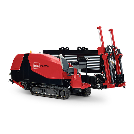
- Page 1 Form No. 3414-730 Rev A 2226 Directional Drill Model No. 23803—Serial No. 400000000 and Up *3414-730* A Register at www.Toro.com. Original Instructions (EN)
- Page 2 Whenever you need service, genuine Toro parts, or additional information, contact an Authorized Service Dealer or Toro Customer Service and have the model and serial numbers of your product ready. Figure 1 identifies the location of the model and serial numbers on the product.
-
Page 3: Table Of Contents
Contents Servicing the Air Cleaner ........72 Servicing the Engine Oil........74 Adjusting the Engine-Valve Clearance ....76 Safety ............... 4 Cleaning the Engine EGR Cooler...... 76 General Safety ........... 4 Inspecting the Engine Crankcase-Breather Tramming Safety ..........5 System............76 Drilling Safety ............. -
Page 4: Safety
Safety Storage ..............99 Troubleshooting ............ 100 Index ..............103 Important: This machine was manufactured according to the appropriate regulatory standards. Modifying this machine in any way may cause it to be out of compliance with those standards and with the instructions in this Operator’s Manual. Modifications to this machine should only be made by only the manufacturer or an Authorized Service Dealer. -
Page 5: Tramming Safety
Tramming Safety • Move slowly when using the pendant for tramming. • Use care when loading or unloading the machine You move the machine to and from the work site with onto a trailer. the use of a travel pendant. When tramming (moving •... -
Page 6: Drilling Safety
Drilling Safety Drilling Danger Zone The danger zone is the area within and around the • Always lower the pipe loading guard before drilling machine where a person is exposed to the risk of (Figure injury. • Always engage the exit side lockout before operating. - Page 7 Utility Line Color • The alarm will sound if the drill contacts an electrical power source. Refer to the following table for the proper utility line • Do not attempt to leave the machine. and the corresponding utility line color (USA and Canada).
-
Page 8: Safety And Instructional Decals
Safety and Instructional Decals Safety decals and instructions are easily visible to the operator and are located near any area of potential danger. Replace any decal that is damaged or missing. decalbatterysymbols g228534 Battery Symbols Figure 5 Some or all of these symbols are on your battery 1. - Page 9 g228521 Figure 6 1. 125-6130 3. 125-6115 2. 125-6128 decal125-6130 125-6130 1. Warning—read the Operator’s Manual; stay at least 3 m (10 ft) away from the front and rear of the machine and 1.8 m (6 ft) away from the sides of the machine. decal125-6128 decal125-6115 125-6128...
- Page 10 g228523 Figure 8 1. 137-7167 g228522 Figure 7 1. 137-7166 decal137-7167 137-7167 1. Thrown object hazard—keep bystanders away from the machine. decal137-7166 137-7166 1. Crushing hazard—do not stand under the machine.
- Page 11 g228524 Figure 9 1. 137-7168 g228525 Figure 10 1. 137-7172 decal137-7168 137-7168 1. Electrocution hazard—do not touch the machine when the alarm is sounding. decal137-7172 137-7172 1. Runover/backover hazard—read the Operator’s Manual.
- Page 12 g228526 Figure 11 decal137-7164 137-7164 1. 125-6127 3. 137-7164 1. Read the Operator’s Manual—rotate counter clockwise 2. 125-6129 4. 137-7174 to disconnect the battery; rotate clockwise to connect the battery; the negative post is located below the switch; the positive post is located to the side of the switch. decal125-6127 125-6127 1.
- Page 13 decal137-7175 137-7175 1. Rotate the operator platform. g231766 Figure 12 1. 125-6152 3. 137-7175 2. 137-7171 g228528 Figure 13 decal125-6152 125-6152 1. 125-6694 1. Move seat forward and backward. decal125-6694 125-6694 1. Tie-down location decal137-7171 137-7171 1. Falling hazard—do not ride on the machine while it is moving.
- Page 14 g228532 Figure 14 1. 137-7179 2. 137-7178 g228533 Figure 15 1. 125-6197 2. 125-4967 decal137-7179 137-7179 decal125-6197 125-6197 1. Warning—hazardous area; keep at least 3 m (10 ft) away from the machine during operation. 1. Max weight limit—1342 kb (2,958 lb) decal137-7178 137-7178 1.
- Page 15 decal125-8473 125-8473 1. Explosion hazard—wear 3. Fire hazard—keep open eye protection. flames away. 2. Caustic liquid/chemical 4. Poison hazard—do not burn hazard—rinse tamper with the battery. affected area and seek medical assistance. g228531 Figure 16 1. 137-7180 3. 125-6119 2. 125-8473 decal125-6119 125-6119 1.
- Page 16 decal117-2718 117-2718 g228960 Figure 17 1. 117-2718 2. 137-7161 decal137-7161 137-7161 1. Engine—stop 5. Headlights 2. Engine—run 6. On 3. Engine—start 7. Off 4. Spray gun...
- Page 17 decal125-6140 125-6140 1. Rotate the chair. g228527 Figure 18 1. 125-6140 3. 137-7182 2. 137-7183 4. 125-6124 decal137-7183 137-7183 1. Read the Operator’s Manual.
- Page 18 decal137-7182 137-7182 1. Load pipes from back row first. decal125-6124 125-6124 1. Center the pipe joint between the upper and lower wrenches.
- Page 19 decal137-7165 137-7165 1. Antifreeze g228530 Figure 19 1. 137-7165 4. 137-7170 2. 125-8483 5. 127-1829 3. 137-7169 decal125-8483 125–8483 1. Hydraulic fluid; read the Operator’s Manual. decal137-7169 137-7169 1. Warning—read the Operator’s Manual. 4. Warning—keep away from moving parts; keep all guards and covers in place.
- Page 20 decal137-7170 137-7170 g228520 Figure 20 1. Falling hazard—do not climb on the machine while it is moving. 1. 125-6107 decal127-1829 127-1829 1. Oil drain decal125-6107 125-6107 1. Crushing hazard of hand and foot—keep hands and feet away.
- Page 21 g231767 Figure 21 1. 137-7177 3. 125-6193 2. 137-7176 4. 125-6194 decal137-7177 137-7177 1. Mud—On/Off 8. Carriage thrust speed—high 2. Upper wrench—open/close 9. Mud flow—high 3. Lower wrench—open/close 10. Thrust the carriage forward (drill mode I and II); lower the stake (setup mode) 4.
- Page 22 decal137-7176 137-7176 1. Engine—start 10. Rotate the cam assembly. 2. Engine speed—increase 11. Move to the next or previous step in SmartTouch™ mode. 3. Engine speed—decrease 12. Cam override function to rotate the cam assembly. 4. Pipe gripper arm—retract 13. Lower the stake (setup mode);...
- Page 23 decal125-6193 125-6193 1. Exit-side lockout—reset 5. Tramming and setup 2. Exit-side lockout switch 6. Drilling 3. Ground-strike—reset 7. Work lights—on 4. Ground-strike switch 8. Work lights—off decal125-6194 125-6194 1. Exit-side-lockout receiver battery-status light 4. Emergency engine stop—engage 2. Exit-side lockout drill-enabled light 5.
-
Page 24: Product Overview
Product Overview g218957 Figure 22 Left Side View 1. Pipe box 3. Stabilizer foot 2. Safety bar g218958 Figure 23 Rear View 1. Rear control panel 3. Zap-alert stake 2. Drilling-fluid-source connection... - Page 25 g218959 Figure 24 Right Side View 1. Carriage 6. Thrust frame 2. Zap-alert strobe 7. Stabilizer foot 3. Front hood 8. Rear hood 4. Front control panel 9. Tracks 5. Operator seat...
- Page 26 g218960 Figure 25 Top view 1. Carriage 5. Lower wrench 2. Drill spindle 6. Pipe wiper 3. Thrust frame 7. Stake-down tube 4. Upper wrench...
-
Page 27: Controls
Controls Operator-Platform Latch The operator platform swings out away from the Refer to the following sections for the appropriate machine, making room for you to sit. It has 5 positions: machine controls: travel (swung all the way into the machine), full-out, •... - Page 28 Adjusting the Operator Console Bolts Tighten the console bolts to add friction to the consoles; refer to Figure The left console can rotate 10 degrees in. The right console can rotate 10 degrees in and 45 degrees out. g230008 Figure 28...
-
Page 29: Front Control Panel
Front Control Panel Emergency Engine Stop Button Push this button (Figure 29) to immediately shut off the engine and all drilling operations. You must pull this button out before you can start the engine again. Exit-Side Lockout—Standby Light This light (Figure 29) illuminates orange when the exit-side lockout is turned off, indicating that you may... - Page 30 Joysticks in Setup Mode The machine must be in setup mode (Figure 29) and you must be in the seat to use these functions. g225942 Figure 30 Joysticks – Setup Mode 1. Lower the left stake down 5. Lower the right stake down 2.
- Page 31 Left Joystick g226145 Figure 31 Left Joystick in mode DRILL 1. Raise the elevator 6. Go to the next step in SmartTouch™ mode 2. Lower the elevator 7. Retract the pipe gripper arm 3. Open / Close the pipe gripper 8.
- Page 32 Right Joystick The joystick controls vary depending on the control mode you select when powering up the machine. There are 2 control modes: Drill Mode I and Drill Mode II; refer to the Control-Select Screen in the Software Guide for information on setting the control modes.
-
Page 33: Rear Control Panel
Exit Side Lockout • Engine-off position—turn the key to this position to shut off the engine. The engine cannot be started The exit-side-lockout system provides the individuals from the operator platform when the key is in this working around the machine with a means to disable position. -
Page 34: Specifications
Battery-Disconnect Switch If you release the operator presence switch while operating, you will need to release all of the controls Open the front hood to access the before resuming operation. switch; refer to Opening ATTERY ISCONNECT the Front and Rear Hoods (page 67). -
Page 35: Before Operation
• Keep the manual(s) with the machine. Go to to complete the job; refer to Gathering Site www.Toro.com for a replacement manual. Information (page 36). Plan the bore path. Fuel Safety Before drilling, plan the bore path based on the •... -
Page 36: Gathering Site Information
Gathering Site Information Refer to Preparing the Job Site and the Machine (page 44) for instructions on preparing the job site and the machine. Planning the Initial Path Drill the bore. Before drilling, plan the path you will bore and prepare Drill the bore in 3 stages: as follows: Entry... - Page 37 – Crystalline silica and other dust DANGER If you will be drilling through or cutting concrete, Drilling into an electric power line sand, or other substances that create dusts will cause the machine to become or fumes, you need to ensure that you and all electrified and may electrocute you or workers wear breathing protection to protect any bystanders.
- Page 38 WARNING Machining or handling stone, masonry, concrete, metal, and other materials can generate dust, mists, and fumes containing chemicals, such as silica, known to cause serious or fatal injury or illness, such as respiratory disease, silicosis, cancer, birth defects, or other reproductive harm.
-
Page 39: Planning The Bore Path
Planning the Bore Path Before setting up the job site, you need to plan the bore path, including the following: g218955 Figure 40 1. Bore entry 4. Obstacle 2. Beginning of bore-at-depth point 5. End of bore-at-depth point and bore exit 3. - Page 40 g021765 Figure 41 1. 20 cm (8 inches) This flexibility is often rated in materials as a minimum bend radius, which is the radius of the circle formed if the material or pipes, connected together, were bent to form a giant circle. The minimum radius of a circle made with the pipe used with this machine is 31 m (101 ft).
- Page 41 Given the information in the table, you can calculate the number of pipes required to reach your beginning point at the appropriate depth. Toro recommends that you start the entry point a distance back from your beginning-at-depth point by the same distance as the length of pipes you will need to reach that point. This will...
- Page 42 The following example illustrates the process given an installation using the maximum entry pitch of the machine (26%) on level ground: g218954 Figure 44 1. 26% pitch 4. 185 cm (73 inches) 7. 14.7 m (45 ft) 2. 76 cm (30 inches) 5.
- Page 43 The following example illustrates the process given an installation using the machine at an 18% pitch on level ground: g218952 Figure 45 1. 18% pitch 3. 96 cm (38 inches) 5. 119 cm (47 inches) 2. 53 cm (21 inches) 4.
-
Page 44: Preparing The Job Site And The Machine
Preparing the Job Site and Checking the the Machine Safety-Interlock Switches Before drilling, prepare the job site and machine as Checking the Operator Presence follows: Safety-Interlock Functions on the • Marking and Preparing the Bore Path (page 44) Operator Platform •... -
Page 45: Testing The Zap-Alert System
Checking the Pipe Load Guard audible alarm in the event that the drill bit, reamer, or stake breaks into an energized power line. In the Safety Interlock Functions event of an electric strike, the machine becomes energized, setting off the alarm. You will need 2 people for this procedure. -
Page 46: Mounting A Fire Extinguisher
Mounting a Fire Extinguisher Mount your fire extinguisher below the operator seat (Figure 50). Note: A fire extinguisher is not provided with the machine. The recommended fire extinguisher is a dry chemical fire extinguisher approved for class B and C fires. g230009 Figure 48 Operate and maintain the fire extinguisher per the... -
Page 47: Performing Daily Maintenance
• • Never keep fuel in containers with zinc plating on Fuel filter plugging may be expected for a time the inside. after converting to biodiesel blends. • • Do not use fuel additives. Contact your Authorized Service Dealer for more information on biodiesel. -
Page 48: Tramming The Machine
Loading and Unloading the emergency-engine-stop buttons are released (Figure 29 Figure 38). Machine Turn the key to the S position until the TART engine starts, then release it. WARNING To shut off the engine, turn the key to the O position. - Page 49 Place a block at the front and rear of the trailer Lower the stabilizers until the stabilizer feet and/or truck tires. contact the trailer floor. Using the travel pendant, set the engine and the Turn off the engine. tram speed to slow. Use appropriately rated chains and binders Using the travel pendant, carefully tram the to secure the rings on the left and right track...
-
Page 50: Setting Up The Drill Head And Tracking System
Setting Up the Drill Head and Tracking System The drill head consists of 2 parts, the drill bit and the sonde housing (Figure 54). g023073 Figure 55 g023076 Figure 54 1. Sonde housing 4. Housing cover 1. Sonde housing 2. Drill bit 2. -
Page 51: Setting Up The Machine For Drilling
Setting up the Machine for Deploying the Zap-Alert System Drilling Using the travel pendant, tram the machine The Zap-Alert system is an electric strike sensing to the location that you have prepared for it, device on the machine that triggers a strobe light and ensuring that the front of the machine is the audible alarm in the event that the drill bit, reamer, proper distance back from entry point and the... -
Page 52: Lowering The Stakes
g218964 Figure 60 1. Thrust frame 2. Stake-down plate Lower the rear stabilizers until they contact the ground firmly, or until the desired entry angle is achieved (Figure 61). Note: The rear of the tracks should just start to g218966 Figure 59 lift off the ground. - Page 53 Setting Up the Pump to Use a refer to your mixing system Operator’s Manual for details. Natural Water Source Conversely, for some jobs (depending on the soil type To set up a pump to use a natural water source, and distance), you can pump screened water from a ensure that you use the Y-screen to filter all materials natural water source, such as a lake or river, through other than water.
-
Page 54: During Operation
– Wait for all moving parts to stop. • Do not operate the machine when there is the risk of lightning. • Do not use the machine as a towing vehicle. • Use accessories, attachments, and replacement parts approved by The Toro® Company only. -
Page 55: Diesel Particulate Filter Regeneration
Diesel Particulate Filter • When enough soot accumulates, the computer informs you that it is time to regenerate the diesel Regeneration particulate filter. • DPF regeneration is a process that heats the DPF The diesel particulate filter (DPF) is part of the exhaust to convert the soot to ash. - Page 56 Types of Diesel Particulate Filter Regeneration Types of diesel particulate filter regeneration that are performed while the machine is operating: Type of Regeneration Conditions for DPF regeneration DPF description of operation Passive Occurs during normal operation of the machine at The display does not display an icon indicating high-engine speed or high-engine load passive regeneration.
-
Page 57: Drilling The Bore
Passive DPF Regeneration Drilling the Bore • Passive regeneration occurs as part of normal engine operation. Starting the First Pipe • While operating the machine, run the engine at The Software Guide is used in this procedure. full-engine speed when possible to promote DPF regeneration. - Page 58 Using the exit-side-lockout transmitter, enable the exit side lockout. Hand thread the lead bar onto the pipe threads then clear away from the front of the machine. When the area is clear of people, push the exit-side-lockout reset switch on the front control panel.
- Page 59 Boring the Entry Shaft Rotate the drill spindle clockwise and move the carriage slowly forward to insert the spindle into The first step is to create the entry shaft. Push and the female end of the pipe (Figure 65). bore the drill bit and the first few pipes into the ground Note: Tighten the joint until the pipe is rotating at an angle from 0 to 16 degrees (with the tracks flat...
-
Page 60: Backreaming And Pullback
Exiting the Ground ft) of forward travel. If you steer more than this, you will damage the drill pipes. As you approach the end of the bore, steer the drill head to the exit point, keeping the steering limits in Boring the Horizontal Shaft mind as you do so. - Page 61 Using breakout tools, remove the drill head from the lead bar. Important: Do not use pipe wrenches. Double check the reamer to ensure that the fluid ports are clean and free from obstructions. Install the reamer and swivel onto the end of the lead bar as directed by the reamer manufacturer.
-
Page 62: After Operation
Rotate the drill spindle counterclockwise moving Remove the reamer from the end of the lead bar rearward slowly until the spindle fully separates as directed by the reamer manufacturer. from the pipe. Release the lower wrench and pull the lead bar Send the carriage to the rear stop on the thrust out of the pipe guide. -
Page 63: Finishing The Job
Finishing the Job Adjusting the TJC-spray Volume To adjust the volume of thread-joint compound that is Complete the following after each day of use: delivered by the applicator, complete the following: • Connect the hand spray gun to the pump and clean Loosen the jam nut on the adjustment bolt the machine with clean water;... -
Page 64: Moving A Disabled Machine
Filling the TJC Applicator Moving a Disabled Machine Stop the machine and shut off the engine. Whenever the machine is stopped and the engine is not running, the hydrostatic brakes automatically Loosen the wing nuts securing the cover straps engage. Do not attempt to tow the machine if it cannot to the machine (Box A of Figure 72). -
Page 65: Maintenance
Replace all covers and guards after you service or clean the machine. Do not operate the machine without the covers or guards in place. Note: Download a free copy of the electrical or hydraulic schematic by visiting www.Toro.com and searching for your machine from the Manuals link on the home page. Important: Refer to your engine owner’s manual for additional maintenance procedures. - Page 66 Maintenance Service Maintenance Procedure Interval • Adjust the engine-valve clearance (if necessary). • Drain and clean the fuel tank. • Change the planetary oil (or yearly, whichever comes first). • Check the rotary gearbox drive oil (or yearly, whichever comes first). •...
-
Page 67: Pre-Maintenance Procedures
Pre-Maintenance Procedures Pre-Maintenance Safety – Allow machine components to cool before performing maintenance. • Before adjusting, cleaning, repairing, or leaving the machine, do the following: • If possible, do not perform maintenance while the engine is running. Keep away from moving parts. –... -
Page 68: Using The Cylinder Lock
Using the Cylinder Lock Lubrication WARNING Greasing the Machine The thrust frame may lower when it is in the Service Interval: Before each use or daily (Grease raised position, causing serious injury or immediately after every washing). death. Grease type: General-purpose grease. Install the cylinder lock before performing maintenance that requires the thrust frame Total number of grease fittings: 51... - Page 69 g220078 Figure 78 Cam Assembly (Operator Side)—2 fittings g222835 Figure 79 Left Side, Front Cam Assembly—4 fittings...
- Page 70 g222836 Figure 80 Left Side, Rear Cam Assembly—4 fittings g222837 Figure 81 Tracks—12 fittings (6 on each side)
- Page 71 g220081 Figure 82 Stabilizer Feet—8 fittings (4 on each foot) g220082 Figure 83 Stakedown Motors—2 fittings g224193 Figure 84 Stakedown Cylinders—4 fittings (2 fittings on each cylinder)
-
Page 72: Engine Maintenance
Engine Maintenance Engine Safety • Shut off the engine before checking the oil or adding oil to the crankcase. • Do not change the governor speed or overspeed the engine. g223045 Figure 85 Servicing the Air Cleaner Lift Cylinder (Drill/Carriage Side; lower grease fitting is behind the track roller)—3 fittings Check the air-cleaner body for damage that could cause an air leak and replace it if it is damaged. - Page 73 g008909 Figure 88 1. Air-cleaner cover 2. Air-cleaner latch Remove the cover from the air-cleaner body. Before removing the filter, use low-pressure air (275 kPa or 40 psi, clean and dry) to help remove large accumulations of debris packed between the outside of the primary filter and the canister.
-
Page 74: Servicing The Engine Oil
Alternate oil: SAE 10W-30 or 5W-30 (all damage the filter. temperatures) Clean the dirt-ejection port located in the Toro Premium Engine Oil is available from your removable cover. Authorized Service Dealer in either 15W-40 or Remove the rubber outlet valve from the cover, 10W-30 viscosity grades. - Page 75 g220795 g220852 g031256 Figure 91 g220851 Figure 92 Changing the Engine Oil and Change the engine-oil filter (Figure 94). Engine-Oil Filter Note: Ensure that the oil-filter gasket touches Service Interval: After the first 50 hours—Change the engine, and then an extra 3/4 turn is the engine oil and engine-oil filter.
-
Page 76: Adjusting The Engine-Valve Clearance
Adjusting the Engine-Valve Clearance Service Interval: Every 800 hours Refer to your engine owner’s manual for the adjustment procedure. Cleaning the Engine EGR Cooler Service Interval: Every 1,500 hours For information on cleaning the engine EGR cooler, refer to your engine owner’s manual. g220797 Figure 93 Inspecting the Engine... -
Page 77: Inspecting And Cleaning Engine-Emission-Control Components And Turbocharger
Inspecting and Cleaning Fuel System Engine-Emission-Control Maintenance Components and Servicing the Fuel System Turbocharger Service Interval: Every 3,000 hours Draining the Fuel Tank For information on inspecting and cleaning the Service Interval: Every 800 hours—Drain and clean engine-emission-control components, refer to your the fuel tank. -
Page 78: Replacing The Fuel Filter Element
Replacing the Water-Separator Remove the filter and clean the filter-head-mounting surface (Figure 96). Element Lubricate the filter gasket with clean, engine oil; Place a clean container under the water refer to the engine owner's manual (included separator. with the machine) for additional information. Drain some fuel by loosening the vent plug and Install the dry filter canister, by hand, until the opening the drain valve... -
Page 79: Electrical System Maintenance
Rinse with clear water. Coat the battery posts and cable connectors with Grafo 112X (skin-over) grease a metal object. (Toro Part No. 505-47) or petroleum jelly to prevent • Do not weld, grind, or smoke near a battery. corrosion. Note: The electrical system in this machine is 12 V. -
Page 80: Charging The Battery
Charging the Battery Battery-Charger Table Charger setting Charging time WARNING 10 A 8 to 10 hours Charging the battery produces gasses that 20 A 4 to 6 hours (do not exceed 6 hours) can explode. When the battery is fully charged, unplug Do not smoke near the battery and keep the charger from the electrical source, then sparks and flames away from battery. -
Page 81: Drive System Maintenance
Planetary drive oil capacity: approximately 1.4 L (negative) (positive) (1.5 US qt) Toro Premium Gear Oil is available from an Authorized Connect the positive (+) jumper cable to the Service Dealer. See the Parts Catalog for part jump post (Figure 98). -
Page 82: Changing The Planetary Drive Oil
Checking the Rotary Repeat steps through to check the planetary-drive oil level on the other side of the Gearbox Drive Oil machine. Service Interval: Before each use or daily—Check Changing the Planetary the rotary gearbox drive oil. Every 800 hours—Check the rotary gearbox Drive Oil drive oil (or yearly, whichever comes first). -
Page 83: Changing The Rotary Gearbox Drive Oil
Changing the Rotary Gearbox Drive Oil Service Interval: After the first 100 hours—Change the gearbox-drive oil. Every 800 hours—Change the gearbox-drive oil (or yearly, whichever comes first). Note: Change the oil when it is warm, if possible. Move the machine to a level surface and move the carriage all the way to the rear stop. -
Page 84: Servicing The Tracks
Servicing the Tracks Loosening the Track Tension If the track seems tight, loosen the track tension as Service Interval: Before each use or daily—Check follows: the track tension. Move the machine to a level surface and raise WARNING the thrust frame and stabilizers so that the tracks are raised. -
Page 85: Cooling System Maintenance
Checking the Coolant Level Cooling System in the Reservoir Maintenance Service Interval: Before each use or daily Coolant specification: 50/50 solution of ethylene-glycol antifreeze and water or equivalent Important: Do not remove the radiator filler cap during this procedure. Engine and Radiator coolant capacity: 16.77 L (17.7 US qt) Move the machine to a level surface, shut off the engine, and remove the key. -
Page 86: Checking The Coolant Level In The Radiator
Checking the Coolant Level If the coolant level is low, add coolant until the level is up to the bottom of the filler neck (Figure in the Radiator 105). Important: Do not overfill the radiator. Service Interval: Every 50 hours Note: If the radiator coolant level is low and the WARNING... -
Page 87: Cleaning The Cooling System
Cleaning the Cooling Flushing the Cooling System System Engine and radiator coolant capacity: 16.8 L (17.7 US qt) Service Interval: Every 800 hours/Yearly (whichever Move the machine to a level surface, shut off comes first) (Clean the cooling the engine, and remove the key. system if the coolant becomes dirty Condition the cooling system as follows: or rust colored.) - Page 88 Filling the System with Coolant Clean the threads on the drain plug and apply 3 layers of PTFE sealing tape. Important: You must fill the cooling system Close the drain plug. properly to prevent air pockets in the cooling passages. Failing to vent the cooling system Flush the cooling system as follows: properly can severely damage the cooling system Open the filler-neck cap.
-
Page 89: Belt Maintenance
Belt Maintenance Checking the Belt Tension Service Interval: Every 800 hours Servicing the Engine-Drive Move the machine to a level surface, shut off the engine, and remove the key. Belt Open the front hood. Align a straight edge over the drive belt and WARNING across the pulleys (Figure... -
Page 90: Hydraulic System Maintenance
Authorized Service Dealer for part numbers.) Check the tension of the belt; refer to Checking Alternate fluids: If the Toro fluid is not available, other the Belt Tension (page 89). fluids may be used provided they meet all the following If the belt tension is correct, tighten the nut and material properties and industry specifications. - Page 91 Order the hydraulic oil from your Authorized Service Dealer. Note: If ambient operating temperatures exceed 43° C (110° F), contact Toro for fluid recommendations. Checking the Hydraulic Fluid Service Interval: Before each use or daily Check the hydraulic fluid as follows: Move the machine to a level surface, shut off the engine, and remove the key.
- Page 92 Changing the Hydraulic-Fluid Changing the Hydraulic-Charge Return Filter Filter Service Interval: Every 800 hours/Every 6 months Service Interval: Every 800 hours/Every 6 months (whichever comes first) (whichever comes first) Move the machine to a level surface, shut off Move the machine to a level surface, shut off the engine, and remove the key.
- Page 93 Changing the Hydraulic Fluid Service Interval: Every 800 hours/Yearly (whichever comes first) Important: If the fluid becomes contaminated, contact your Authorized Service Dealer, because the system must be flushed. Contaminated fluid looks milky or black when compared to clean oil. Important: Use of any other filter may void the warranty on some components.
-
Page 94: Drilling-Fluid Pump Maintenance
WARNING C (32° F) Hydraulic fluid escaping under pressure can Toro Premium Engine Oil is available from your penetrate skin and cause injury. dealer. See the parts catalog for part numbers. Also, refer to the engine owners manual, included with the •... -
Page 95: Preparing The Drilling-Fluid System For Cold Weather
Preparing the Drilling-Fluid Oil (page 95) and add the necessary amount of oil. System for Cold Weather Changing the Drilling-Fluid Pump Prepare the machine as follows after drilling if the temperature will be below 0° C (32° F). Move the machine to a level surface, shut off Service Interval: Every 400 hours—Change the the engine, and remove the key. - Page 96 Open the antifreeze valve on the front side of the drilling-fluid pump as shown in Figure 120. Start the machine and turn On the drilling-fluid pump. Add antifreeze to the tank as needed (Figure 120). When the antifreeze comes out of the drill spindle (Figure 118), turn the pump off.
-
Page 97: Controls Maintenance
Controls Maintenance Cleaning Calibrating the Joysticks Cleaning with the and the Travel Pendant Spray-Hose Attachment Service Interval: Every 400 hours Service Interval: Before each use or daily Refer to the joystick section of the Software Guide The machine comes with a spray-hose attachment for this procedure. -
Page 98: Cleaning Plastic And Resin Parts
Turn the drilling-fluid pump to the O position through the display screen; refer to the Main Drill Functions Displayed in the Pressure Screen in the Software Guide. Using the spray-hose attachment, hold down the lever and spray down the machine and pipes. Cleaning Plastic and Resin Parts Avoid using gasoline, kerosene, paint thinner, etc. - Page 99 Storage Shut off the engine and remove the key. Remove dirt and grime from the entire machine. Important: You can wash the machine with mild detergent and water. Avoid excessive use of water, especially near the control panel, engine, hydraulic pumps, and motors. Service the air cleaner;...
- Page 100 Troubleshooting Problem Possible Cause Corrective Action The machine is not responding to the 1. The joysticks need to be calibrated. 1. Calibrate the joysticks. controls properly. 2. The cam assembly needs to be 2. Calibrate the cam assembly; refer to calibrated.
- Page 101 Problem Possible Cause Corrective Action The engine starts, but does not keep 1. The fuel tank vent is restricted. 1. Loosen the cap. If the engine runs with running. the cap loosened, replace the cap. 2. Dirt or water is in the fuel system. 2.
- Page 102 Problem Possible Cause Corrective Action The engine overheats. 1. More coolant is needed. 1. Check and add coolant. 2. There is restricted air flow to the 2. Inspect and clean the side panel radiator. screens with every use. 3. The crankcase oil level is incorrect. 3.
- Page 103 Index Engine-stop ....29, 33–34, 81 Draining the water separator ... . . 77 Drill bits ........50 811 ......
- Page 104 Boring........59 Hydraulic system Error indicator light ......33 Lines and hoses Maintenance .
- Page 105 Loading ........46 Checking Symbol Pipe load guard Testing .
- Page 106 Deploying....... . 52 Ground-strike-reset switch ... . . 29 Grounding stake Storage .
- Page 107 Notes:...