Advertisement
Quick Links
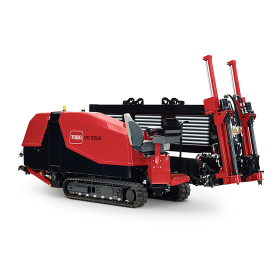
2226 Directional Drill
Model No. 23803—Serial No. 400000000 and Up
This machine is a prototype unit.
Safety
Improper use or maintenance by the operator can
result in injury. To reduce the potential for injury,
comply with these safety instructions and the safety
instruction throughout this document, denoted by the
safety-alert symbol
, which means: Caution , Warning ,
or Danger —personal safety instruction. Failure to
comply with the instruction may result in personal injury
or death.
This product is capable of amputating hands and feet. Follow
all safety instructions to avoid serious injury or death.
The owner/user can prevent and is responsible for accidents
or injuries occurring to people, or damage to property.
Important: Before operating in an area with
high-voltage lines or cables, contact a "One-Call System
Directory" service. In the USA, call 811 or your local
utility company. If you do not know your local utility
company's phone number, call the national number
(USA and Canada only) at 1-888-258-0808. Also, contact
any utility companies that are not participants of the
"One-Call System Directory" service.
•
Read and understand the contents of the manual before
you start the machine. Make sure everyone using this
machine knows how to use it and understands the
warnings.
•
Do not put hands or feet near moving components on
the machine.
•
Keep bystanders a safe distance from the machine.
•
Do not operate machine without all guards and other
safety protective devices in place and working on the
machine.
•
Keep children out of the operating area and under the
watchful care of a responsible adult other than the
operator. Never allow children to operate the machine.
•
Shut the machine off before servicing, fueling, or
unplugging.
© 2017—The Toro® Company
8111 Lyndale Avenue South
Bloomington, MN 55420
Training
•
•
•
•
Preparation
•
•
•
•
•
•
Register at www.Toro.com.
Read the Operator's Manual and other training material.
Note: If the operator(s) or mechanic(s) cannot read
English, it is the owner's responsibility to explain this
material to them.
Become familiar with the safe operation of the equipment,
operator controls, and safety signs.
All operators and mechanics should be trained. The
owner is responsible for training the users.
Do not let children or untrained people operate or service
the equipment. Local regulations may restrict the age of
the operator.
Evaluate the terrain to determine what accessories and
attachments are needed to properly and safely perform
the job. Only use accessories and attachments approved
by the manufacturer.
Wear appropriate clothing; including a hard hat, safety
glasses, long pants, safety shoes, and hearing protection.
Tie back long hair. Do not wear jewelry. Secure loose
clothing.
Inspect the area where the equipment is to be used and
ensure that all objects are removed from the machine
before use.
Use extra care when handling fuels. They are flammable
and vapors are explosive.
– Use only an approved container.
– Do not remove the fuel cap or add fuel with the
engine running. Allow the engine to cool before
refueling. Do not smoke near the machine when the
engine is running.
– Do not refuel or drain the machine indoors.
Check that the operator's presence controls, safety
switches, and shields are attached and functioning
properly. Do not operate the machine unless they are
functioning properly.
Original Instructions (EN)
All Rights Reserved *3412-311* A
Printed in the USA
Form No. 3412-311 Rev A
Quick Start Guide
Advertisement

Related Manuals for Toro 2226


Summary of Contents for Toro 2226
- Page 1 Form No. 3412-311 Rev A 2226 Directional Drill Model No. 23803—Serial No. 400000000 and Up Quick Start Guide This machine is a prototype unit. Safety Training • Read the Operator's Manual and other training material. Improper use or maintenance by the operator can result in injury.
- Page 2 General Operation • Operate the drive pendant alongside the machine outside of the danger zone (Figure • Do not run the engine in an enclosed area. • Keep all bystanders away while moving the machine. • Do not operate without the guards securely in place. Be sure all interlocks are attached, adjusted, and functioning •...
- Page 3 Drilling Safety includes where a person can be reached by operational movement of the machine, its working devices, auxiliary Ensure that no one approaches a pipe while it is spinning. equipment, or swinging/falling equipment. The pipe can snag on clothing and cause amputation or Note: The danger zone defines the amount of space death.
- Page 4 Utility Line Color Refer to the following table for the proper utility line and the corresponding utility line color (USA and Canada). Utility Line Utility Line Color Electric Telecommunication, alarm or signal, cables, or conduit Orange Natural gas, oil, steam, petroleum, or other gaseous or flammable Yellow material Sewer and drain...
- Page 5 • Clean debris from attachments, drives, mufflers, and • Use only genuine Toro replacement parts to ensure that engine to help prevent fires. Clean up oil or fuel spillage. original standards are maintained. • Let the engine cool before storing and do not store near •...
- Page 6 Product Overview g194439 Figure 3 1. Drill carriage 6. Right Stabilizer 2. Zap alert strobe 7. Rear hood 3. Operator seat 8. Front hood 4. Control panel 9. Track 5. Thrust frame g194440 Figure 4 1. Pipe holder 3. Left stabilizer 2.
- Page 7 g194441 Figure 5 1. Drill carriage 4. Upper wrench 2. Drill spindle 5. Lower wrench 3. Thrust frame 6. Pipe wiper...
- Page 8 Operation You drill the bore in three stages: A. Entry Understanding Horizontal In the entry phase of the bore, you push the drill bit and head into the ground at an angle of up to Directional Drilling 16 degrees. After pushing in one or more pipes, you begin drilling down and forward until you Horizontal directional drilling is a process used for drilling a reach the desired depth or depth-gauge hole (if...
- Page 9 Gathering Site Information DANGER Contacting underground hazards with the Planning the Initial Route machine while drilling or reaming can cause explosion, electrocution, breathing problems, Before you can begin boring, you need to plan the route you severe trauma, and death to you or bystanders. will bore and prepare as follows: –...
- Page 10 – Electrical power lines – Crystalline silica and other dust If you will be drilling through or cutting concrete, DANGER sand, or other substances that create dusts or fumes, you need to ensure that you and all workers wear Drilling into an electric power line will cause breathing protection to protect your lungs from the the machine to become electrified and may dust.
- Page 11 Planning the Bore Path Before setting up the job site, you need to plan the bore path, including the following: g021764 g021764 Figure 6 1. Bore entry 4. Obstacle 2. Beginning-of-bore-at-depth point 5. End-of-bore-at-depth point and bore exit 3. Bore depth •...
- Page 12 g021765 g021765 Figure 7 1. 20 cm (8 inches) This flexibility is often rated in materials as a minimum bend radius, which is the radius of the circle formed if the material or pipes, connected together, were bent to form a giant circle.
- Page 13 Note: The depths given in the following table are for 3 m (10 ft) of combined drill head and pipe. As you steer up, the pitch of the steered section will change and can be monitored with the receiver. Use the following table to identify how many lengths of pipe will be necessary to insert and steer to the beginning point and help you choose an entry point.
- Page 14 Toro recommends that you start the entry point a (26%) on level ground: distance back from your beginning-at-depth point by the •...
- Page 15 • The following example illustrates the process given an You insert the first 3 m (10 ft) of drill bit/pipe into the installation using the machine at an 18% pitch on level ground with no steering. The end of the drill bit will be ground: 53 cm (21 inches) deep (Figure...
- Page 16 Understanding and Using button sends a signal to the receiver that allows the machine operator to reset the system and restore the thrust and rotary the Exit-side-lockout System functions. (Standard Range) The following table lists the various states of the indicator lights on the handheld transmitter (Figure 13) and their...
- Page 17 Important: Ensure that you install the batteries Indicator Light State Meaning in the correct polarity orientation or you could Green light is blinking rapidly The transmitter is transmitting damage the transmitter. to the base unit Green light is illuminated A button on the transmitter is currently pressed without blinking Yellow light is blinking slowly...
- Page 18 Preparing the Job Site and the complete, the Yellow light turns off, the Red light begins flashing, and the Green light illuminates. All Machine lights remain as mentioned until you release the button. 8. Release the On button. Before drilling, prepare the job site and machine as follows: The Red light turns off and the Green light flashes for •...
- Page 19 Testing the Zap-Alert System The Zap-Alert system is an electric strike sensing device on the machine that triggers a strobe light and audible alarm in the event that the drill bit, reamer, or stake breaks into an energized power line. In the event of an electric strike, the machine will become energized, setting off the alarm.
- Page 20 7. Disconnect the alligator clips from the grounding stud WARNING and the machine. Fuel is harmful or fatal if swallowed. Long-term 8. Store the grounding stake in the holder on the operator exposure to vapors can cause serious injury and platform as shown in Figure illness.
- Page 21 Driving the Machine level in the engine crankcase. The oil should just touch the end of the dipstick. See your Authorized Toro Dealer. 1. Walk around the machine to ensure that no one is near it. Ensure that all bystanders are clear of the area where Checking the Cooling System you will be moving the machine.
- Page 22 Contact your Authorized installed. Toro Dealer for a complete list of available blades. 3. Place a block at the front and rear of the trailer and/or The sondes and receivers are essential to track the position truck tires.
- Page 23 g023073 Figure 21 g022373 Figure 23 3. Insert the sonde beacon with the forward end toward 1. Thrust frame 2. Stake-down plate the drill bit into the sonde housing (Figure 22). 7. Lower the rear stabilizers until they contact the ground firmly, or until the desired entry angle is achieved (Figure 24).
- Page 24 called drilling fluid or “Mud”, through the pipe and into the Setting Up the Pump to Use a Natural Water Source bore. This drilling fluid, or “Mud”, does the following for To set up a pump to use a natural water source, you must your bore: ensure that you use the Y-screen to filter all materials other •...
- Page 25 Drilling the Bore DANGER If the Zap-Alert system activates while drilling, the Starting the First Pipe machine, except for the operator’s platform, will become energized. If you step off the operator 1. Ensure that all bystanders are away from the machine platform or if someone touches the machine or wet and that the exit-side lockout is On.
- Page 26 3. When the area is clear of people, disable the exit-side lockout using the exit-side-lockout transmitter (the OK-to-Drill light on the control panel should illuminate); press the exit-side-lockout, reset switch on the control panel. 4. Pull the drill pipe and lead bar back through the pipe guide and into the wrenches, aligning the thickened upper joint of the lead bar with the upper wrench (Figure...
- Page 27 disconnect from each other and may be disconnected the female end of the previous pipe. Tighten the joint underground. until you reach no more than 2,304 N-m (1,700 ft-lb). 12. Release and retract the pipe gripper, rotating it all the 1.
- Page 28 The reamer is designed to widen the bore, pack the walls and lubricate the passage of the product into the bore. The following reamers are available from your Authorized Toro Dealer in various sizes to meet your needs and soil conditions: •...
- Page 29 This will remove most of the dirt and mud from the 15. Release the upper wrench. pipe as you pull it back into the machine, keeping the machine clean. Contact your Authorized Toro Dealer Note: The machine will stop at the carriage at the to purchase drill-pipe wipers.
- Page 30 5. Remove and store the last pipe; refer to Removing Drill Pipes (page 29). 6. Leave the lead bar clamped in the lower wrench, but do not connect the drill spindle to the lead bar. 7. Remove the reamer from the end of the lead bar as directed by the reamer manufacturer.
- Page 31 Adjusting the TJC-spray Volume Filling the TJC Applicator 1. Stop the machine and stop the engine. To adjust the volume of thread-joint compound that is delivered by the applicator, complete the following: 2. Open the stake-down-guard door. 1. Loosen the jam nut on the adjustment bolt located on 3.