ABB 2600T Series Operating Instruction
Multivariable pressure transmitters
Hide thumbs
Also See for 2600T Series:
- Instruction manual (136 pages) ,
- Operating instructions manual (96 pages) ,
- Operating instruction (48 pages)
Table of Contents
Advertisement
Quick Links
—
A B B M E A S U R E M E N T & A N A LY T I C S | O P E R AT I N G I N S T R U C T I O N
266CRx, 266CSx, 266JRx, 266JSx
Multivariable pressure transmitters
Introduction
—
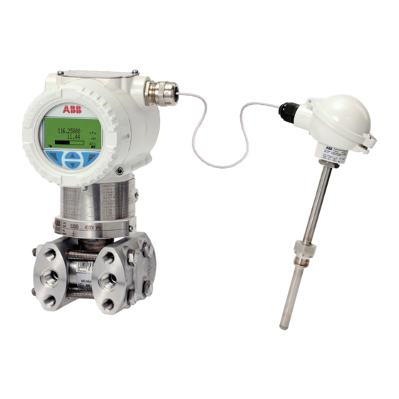
266 multivariable
The 2600T family provides comprehensive range of
top quality pressure measurement products,
specifically designed to meet the widest range of
applications ranging from arduous conditions in
offshore oil and gas to the laboratory environment
of the pharmaceutical industry.
Engineered solutions for all
applications
Measurement made easy
For more information
Further publications for 2600T series pressure
products are available for free download from
www.abb.com/pressure
Advertisement
Table of Contents

Related Manuals for ABB 2600T Series


Summary of Contents for ABB 2600T Series
- Page 1 For more information — 266 multivariable The 2600T family provides comprehensive range of Further publications for 2600T series pressure top quality pressure measurement products, products are available for free download from specifically designed to meet the widest range of www.abb.com/pressure...
- Page 2 Models 266CRH/CRT, 266JRH/JRT Multivariable Models 266CSH/CST, 266JSH/JST Multivariable Additional Information Additional documentation on 2600T series pressure transmitters is available free of charge for downloading at www.abb.com/pressure. Alternatively simply scan this code: Change from one to two columns 2 OI/266CXX/266JXX/HART-EN Rev.
-
Page 3: Table Of Contents
Contents Mounting ................ 13 IP rating ............. 13 ABB .................. 5 Factory settings ..........13 Venting / draining transmitters without diaphragm Introduction ..............5 seals ..............14 About the manual ..........5 Mounting position ..........14 Structure of the operating manual ......5 Mounting dimensions 266CRx/JRx .... - Page 4 Commissioning.............. 33 Specifications ..............73 10.1 General remarks ..........33 14.1 Operating limits 266CRx/JRx ......73 10.2 Output signal ............. 33 14.1.1 Pressure limits ........... 73 10.3 Zero point correction following installation ..33 14.1.2 Temperature limits °C (°F) ........73 ...
-
Page 5: Abb
If it is not possible for you to contact and manufactures products for measurement technology. the ABB subsidiary in your country, you can also contact one We offer our customers application know-how, service, and of the following competence centers for pressure support all over the world. -
Page 6: Safety
Safety Improper use The following are considered to be instances of improper use General information and notes for the reader of the device: These instructions are an important part of the product and — For use as a climbing aid, e.g. for mounting purposes must be retained for future reference. -
Page 7: Plates And Symbols
Failure to observe this safety information may ABB would be pleased to provide support in the selection of result in damage to or destruction of the product suitable materials, however we can assume no liability and / or other system components. -
Page 8: Contents
However, the warranty conditions stipulated in the must observe the following regulations for shipping purposes: order confirmation of the supplier apply. All devices delivered to ABB must be free from any hazardous materials (acids, alkalis, solvents, etc.). 3.12 Safety instructions for electrical installation The electrical connection may only be established by Please contact Customer Center Service acc. -
Page 9: Disposal
ABB can accept and dispose of returns for a fee. ElektroG. If the necessary components are available on the market at the right time, in the future these substances will no longer be used in new product development. -
Page 10: Product Identification
CE mark. hazardous areas. The certification plate shown (A) has been issued for ABB- The name plate (B) provides information including the model APR, 32425 Minden, Germany and bears the following... -
Page 11: Use In Potentially Explosive Atmospheres
Use in potentially explosive For ambient temperatures -40 … 85°C (-40 … 185°F) the atmospheres information based on the temperature classes in the associated certificates, must be complied with. Hazardous atmospheres The temperature sensor circuit (Pt100) and the digital output With or without integrated digital display (pulse / limit value output) must be connected in accordance with the requirements of the Ex certificate. -
Page 12: Function And System Design
Function and system design Change from two to one column Components of the pressure transmitter Fig. 3: Device overview Change from one to two columns The following terminology is used for the different parameters: Product description The 266Jxx/266Cxx multivariable pressure transmitters URL: Upper Range Limit of a specific sensor. -
Page 13: Mounting
Mounting IP rating The housing of pressure transmitters of the R266 series Before installing the transmitter, check whether the device satisfies the requirements of IP degree of protection design meets the requirements of the measuring point from a IP 66 / IP 67 (NEMA 4X) in accordance with IEC 60529. measurement technology and safety specifications point of The first digit indicates the protection of the integrated view. -
Page 14: Venting / Draining Transmitters Without Diaphragm Seals
Venting / draining transmitters without diaphragm Mounting position seals The transmitter can be attached directly on a valve manifold provided for flange installation. Optionally a fastening bracket for wall or pipe installation (2” pipe) is available as an accessory. For models 266CRx and 266JRx fastening brackets must always be used. -
Page 15: Mounting Dimensions 266Crx/Jrx
Mounting dimensions 266CRx/JRx (No design information) - dimensions in mm (inch) 8.5.1 Transmitter with barrel housing Fig. 5: Barrel housing 1 Settings | 2 Rating plate | 3 Certification plate | 3a Optional plate (code I2) | 4 Vent / drain valve | 5 Process connection | 6 Terminal side | 7 LCD display housing cover | 8 Electronics side | 9 Space for removing the cover Note In the case of models with just one remote seal, the threaded connection (1/4 –... -
Page 16: Transmitter With Barrel Housing And Mounting Bracket, For Vertical Or Horizontal Mounting On 60 Mm (2 In.) Pipe
8.5.2 Transmitter with barrel housing and mounting bracket, for vertical or horizontal mounting on 60 mm (2 in.) pipe Fig. 6: Pipe mounting - barrel housing 16 OI/266CXX/266JXX/HART-EN Rev. B | 266CRx, 266JRx, 266CSx, 266JSx... -
Page 17: Transmitter With Din Housing And Mounting Bracket, For Vertical Or Horizontal Mounting On 60 Mm (2 In.) Pipe
8.5.3 Transmitter with DIN housing and mounting bracket, for vertical or horizontal mounting on 60 mm (2 in.) pipe Fig. 7: Pipe mounting - DIN housing 266CRx, 266JRx, 266CSx, 266JSx | OI/266CXX/266JXX/HART-EN Rev. B 17... -
Page 18: Transmitter With Barrel Housing And Flat Bracket, For Vertical Or Horizontal Mounting On 60 Mm (2 In.) Pipe
8.5.4 Transmitter with barrel housing and flat bracket, for vertical or horizontal mounting on 60 mm (2 in.) pipe Fig. 8: Flat bracket for pipe mounting - barrel housing 18 OI/266CXX/266JXX/HART-EN Rev. B | 266CRx, 266JRx, 266CSx, 266JSx... -
Page 19: Montageabmessungen 266Csx/Jsx
Montageabmessungen 266CSx/JSx (not design data) - dimensions in mm (inch) 8.6.1 Transmitter with barrel housing - Horizontal flanges Fig. 9: Barrel housing - horizontal flanges 1 Settings | 2 Rating plate | 3 Certification plate | 4 Vent / drain valve | 5 Process connection | 6 Terminal side | 7 LCD display housing cover | 8 Electronics side | 9 Process flange adapter | 10 Space for removing the cover 54 (2.13) mm (in.) via 1/4 - 18 NPT process flanges 51 (2.01), 54 (2.13), or 57 (2.24) mm (in) via 1/2 - 14 NPT adapter flanges. -
Page 20: Transmitter With Barrel Housing - Vertical Flanges
8.6.2 Transmitter with barrel housing - Vertical flanges Fig. 10: Barrel housing - vertical flanges 1 Settings | 2 Rating plate | 3 Certification plate | 4 Vent / drain valve | 5 Process connection | 6 Terminal side | 7 LCD display housing cover | 8 Electronics side | 9 Process flange adapter | 10 Space for removing the cover 20 OI/266CXX/266JXX/HART-EN Rev. -
Page 21: Transmitter With Mounting Bracket, For Vertical Or Horizontal Mounting On 60 Mm (2 In.) Pipe Pipe
8.6.3 Transmitter with mounting bracket, for vertical or horizontal mounting on 60 mm (2 in.) pipe pipe Fig. 11: Pipe mounting - barrel housing 54 (2.13) mm (in.) via 1/4 - 18 NPT process flanges 51 (2.01), 54 (2.13), or 57 (2.24) mm (in) via 1/2 - 14 NPT adapter flanges. Note: Process connection and seal groove satisfy IEC 161518. -
Page 22: Transmitter With Din Aluminum Housing - Horizontal Flanges With Mounting Bracket For Vertical Or Horizontal Mounting On 60 Mm (2 In.) Pipe
8.6.4 Transmitter with DIN aluminum housing - horizontal flanges with mounting bracket for vertical or horizontal mounting on 60 mm (2 in.) pipe Fig. 12: Pipe mounting - DIN housing 54 (2.13) mm (in.) via 1/4 - 18 NPT process flanges 51 (2.01), 54 (2.13), or 57 (2.24) mm (in) via 1/2 - 14 NPT adapter flanges. -
Page 23: Transmitter With Flat Bracket, For Vertical Or Horizontal Mounting On 60 Mm (2 In.) Pipe
8.6.5 Transmitter with flat bracket, for vertical or horizontal mounting on 60 mm (2 in.) pipe Fig. 13: Flat bracket for pipe mounting - barrel housing With screw plug ** With vent / drain valve Change from one to two columns 266CRx, 266JRx, 266CSx, 266JSx | OI/266CXX/266JXX/HART-EN Rev. -
Page 24: Installation Via (Optional) Mounting Brackets
8.6.6 Installation via (optional) mounting brackets Rotating the transmitter housing With the mounting brackets available the transmitter can be To improve access to electrical connections and for better mounted in different positions. visibility of the optional LCD display in the field, the transmitter housing can be rotated through 360°. -
Page 25: Rotating The Integral Lcd Display
Rotating the integral LCD display — It may be necessary to use condensate vessels or similar If the device has an integral LCD display, this can be mounted with small measuring spans and vaporous media in four different positions, each of which can be rotated —... -
Page 26: Process Connections
8.10 Process connections 8.11 Temperature measurement — Mount the temperature sensor in the downstream pipe of the primary element. — Consider the downstream straight pipe requirements . — If there is a significant difference between the temperature of the measuring medium and the ambient temperature, the measuring error caused by heat conduction must be minimized by insulating the installation location accordingly. -
Page 27: Flow Measurement Of Steam (Condensible Vapor) Or Clean Liquids
8.12.1 Flow measurement of steam (condensible vapor) or 8.12.2 Flow measurement of gas or liquid with solids in clean liquids suspension Fig. 19: Steam flow measurement A High-pressure valve | B Low pressure valve | C Equalizing valve | H High pressure side | L Low pressure side Place taps to the side of the process line. -
Page 28: Fill Level Measurement On Closed Tanks
8.12.3 Fill level measurement on closed tanks Condensing measuring medium (wet leg) Non-condensing measuring medium (dry leg) Fig. 22: Level measurement on closed tanks (wet leg) Mount the transmitter at the same height or below the lowest level to be measured. Fig. -
Page 29: Fill Level Measurement On Open Tanks With Fluids
8.12.4 Fill level measurement on open tanks with fluids 8.12.5 Fill level measurement on the steam boiler (drum water level) Fig. 23: Level measurement on open tanks Mount the transmitter at the same height or below the lowest level to be measured. Connect the high pressure side "+"... -
Page 30: Electrical Connections
Electrical connections Cable connections The electric connection is made using a 1/2-14 NPT or The relevant directives must be complied with for the electrical M20 x 1.5 cable entry. Basically, a metal cable gland should installation! be provided for th Pt100 cable, since a shielded cable will be Because the transmitter cannot be switched off, surge used. -
Page 31: Connection Of The Analog Output (Hart)
Connection of the analog output (HART) DIGI T AL OUTPUT PWR /COMM. USEWIRING RATED 5 °C MIN 5 °C MIN . ABOVE MAX ABOVE MAX . AMBIENT AMBIENT T EMPE RATURE TEST E XT. METER + Kent-Taylo r M10137 Fig. 25: Electrical connections 1 Digital output | 2 Connection for Pt100 resistance thermometer | 3 Internal ground connection | 4 External ground connection | 5 Remote display | 6 Handheld terminal | 7 Power supply Change from one to two columns... -
Page 32: Digital Output (Pulse / Limit Output)
Digital output (pulse / limit output) — Replace the housing cover on the terminal compartment This digital output can be set as a pulse or limit output and tighten it by hand until the cover contacts the housing (transistor output) by making parameter changes using the metal-to-metal. -
Page 33: Commissioning
10 Commissioning 10.2 Output signal If the applied pressure is within the values indicated on the 10.1 General remarks rating plate, the output current ranges between 4 and 20 mA. Once the pressure transmitter has been installed, it is put into If the pressure applied falls outside the set range, the output operation by switching on the operating voltage. -
Page 34: Setting Precalibrated Devices
10.3.1 Setting precalibrated devices 10.3.2 Zero-point increase/suppression on precalibrated (The lower range value has already been set to 0.) devices 266Cxx transmitters do not support this function if the "Level (e.g., 4 ... 20 mA = -100 ... 100 mbar) measurement"... -
Page 35: Configuration
11 Configuration 11.2 Hardware settings The transmitter is delivered preconfigured according to the information provided when placing the order. However, should a change to the configuration be necessary (because measuring point data has changed since the original plans were drawn up, for example), the following options are available: —... -
Page 36: Factory Settings
11.3 Factory settings Replace mode (DIP switches 1 and 2) The transmitters calibrated in the factory to the measuring In normal mode the DIP switches 1 and 2 are in position 0. If a range specified by the customer. The calibrated measuring replacement procedure is necessary, they will be activated. -
Page 37: Configuration Of The Transmitter Without Integrated Lcd Display
11.4 Configuration of the transmitter without integrated 11.4.1 Configuration of LRV and URV (4 … 20 mA range) LCD display 1. Measuring range start pressure (4 mA) - specified by the process or by a pressure generator. Pressure must be stable and must be applied with high accuracy <... -
Page 38: Configuration Of The Pressure Transmitter Menu
11.5 Configuration of the pressure transmitter menu- 11.5.2 Menu levels controlled without integrated LCD display There are two levels under the process display. The LCD display is only used for visualization of the measured values and for configuration of the display and of the transmitter. -
Page 39: Activation Of The Operating Menu
Process display 11.5.3 Activation of the operating menu The process display appears on the LCD display when the To access the operating menu, it must first be activated. device is powered on. It shows information about the device and current process values. Standard LCD indicator (option L1) The manner in which the current process values are shown For devices with standard LCD indicator, unscrew the housing... - Page 40 Error messages on the LCD display Information level (operator menu) If there is an error, a message consisting of a symbol and text On the information level, the operator menu can be used to (e.g. Electronics) appears at the bottom of the process display diagnostic information and choose which operator display.
-
Page 41: Selecting And Changing Parameters
11.5.4 Selecting and changing parameters Calling up the error description Entry from table Additional details about the error that has occurred can be When an entry is made from a table, a value is selected from a called up on the information level. list of parameter values. - Page 42 Parameter name 12.3456 [unit] Next 3. Use to select the next decimal place to change. 4. Use to set the desired value. 5. Use to select the next decimal place. 6. If necessary select and set additional decimal places in accordance with steps 3 to 4.
-
Page 43: Easy Setup
11.5.5 Easy Set-Up Easy Setup The device can be factory parameterized to customer specifications upon request. If no customer information is ABB266 available, the device is delivered with factory settings. Next Edit The setting of the most current parameters is summarized in the "Easy Setup"... - Page 44 Easy Setup Easy Setup Linearization Type Damping Linear 1.0000 Next Edit Next Edit 25. Use to call up edit mode. 37. Use to call up edit mode. 26. Use to select the desired transmission 38. Use to select the desired damping. function.
-
Page 45: Overview Of Parameters On The Configuration Level
11.5.6 Overview of parameters on the configuration level IMPORTANT (NOTICE) This overview of parameters shows all the menus and parameters available on the device. Depending on the version and configuration of the device, not all of the menus and parameters may be visible in it. Easy Setup Language English... - Page 46 MV Setup - Mass Flow MV-Calculation No Calculation Flow Level Medium Static Pressure Unit Min. Stat. Press. abs. Max.Stat. Press. abs. Liquid Water Bias Static Pressure Temperature Unit Saturated Steam Min. Temperature Heated Steam Max. Temperature Primary Device Nozzle ISA 1932 ISO Nozzle ISA 1932 ASME Orifice Corner Taps ISO Orifice Flange Taps ISO...
- Page 47 Meter Tube Material Carbon steel Stainless Steel, ferritic Stainless Steel, austenitic Prim. Elem. Material Bronze SnBz4 Copper E_Cu Calculation of Copper Rg 9 Brass Ms 63 Flow Unit Nickel Flow Hastelloy C Diff. Press. Unit Monel 400 Diff. Press. Value Customer defined Absolute Pressure Temperature...
- Page 48 MV Setup - open Tank MV-Calculation No Calculation Flow Level Level Calculation Level Unit Steam Drum Level Open Tank Closed Tank Closed Tank, 2 Remote Seals Lower Level Dimension b from Fig. 33 Upper Level Dimension d from Fig. 33 Transm.
- Page 49 MV Setup - closed Tank MV-Calculation No Calculation Flow Level Level Calculation Level Unit Steam Drum Level Open Tank Closed Tank Closed Tank, 2 Remote Seals Lower Level Dimension b from Fig. 34 Upper Level Dimension d from Fig. 34 Distance process Dimension e from Fig.
- Page 50 MV Setup - Steam Drum MV-Calculation No Calculation Level Flow Level Level Calculation Level Unit Steam Drum Level Open Tank Closed Tank Closed Tank, 2 Remote Seals Lower Level Dimension b from Fig. 35 Upper Level Dimension d from Fig. 35 Height of Condensate Dimension e from Fig.
- Page 51 MV Setup - 2 Remote MV-Calculation No Calculation Seals Flow Level Level Calculation Level Unit Steam Drum Level Open Tank Closed Tank Closed Tank, 2 Remote Seals Lower Level Dimension b from Fig. 36 Upper Level Dimension d from Fig. 36 Distance process Dimension e from Fig.
- Page 52 Device Setup SW Write Protection Process Variable PV Type Set PV Unit Lower Range Value Upper Range Value Apply PV Parallel Shift Lower Range Value Upper Range Value PV Bias Set PV to Zero Set PV to Value Reset PV Bias Transfer Function Linearization Type Linear...
- Page 53 MV Overview Flow Medium Static Pressure Unit Max.Stat. Press. abs. Min. Stat. Press. abs. Bias Static Pressure Temperature Unit Min. Temperature Max. Temperature Primary Device Meter Tube Material Prim. Elem. Material Flow Unit Flow Diff. Press. Unit Diff. Press. Value Absolute Pressure Temperature Density Unit...
- Page 54 Closed Tank Level Unit Lower Level Upper Level Distance process Connection Transm. mount. Pos. Temperature Unit Min. Temperature Max. Temperature Density Unit Min. Temp. Density Max. Temp. Density Temperature Gas Density Static Pressure Unit Pressure Gas Density Gas Density Tube Temperature Value Condensate Temperature Display...
- Page 55 Security Display Unit Pressure Flow Mass & Volume Lower Range Value Density Upper Range Value Level Other Display Protection Custom Unit Change Password Process Alarm Fail Safe Type Fail Safe Level Down Saturation Limits Low Saturation High Saturation Process Alarm Low Alarm High Alarm Calibration...
- Page 56 Totalizer Input Status Start, Stop Setting Mode Normal, Batch, Forward/Reverse, Forward + Reverse, Selector Forward - Reverse Scaled Output, Mass Flow, Volume Flow, Heat Flow Totalizer 1 Unit Conversion Fact. Totalizer 2 Unit Conversion Fact. Totalizer Batch Reset Count direction Preset Value Status Password...
-
Page 57: Configuration With The Pc / Laptop Or Handheld Terminal
The 266 multivariable transmitters can be configured with the aid of the following devices: When using a graphic user interface (DTM) all configuration — Handheld terminals such as the ABB DHH800 MFC, or possibilities are available. from a different manufacturer, with the prerequisite that... -
Page 58: Damping And Transmission Function
11.7 Damping and transmission function 11.7.2 Transmission function 11.7.1 Damping In the evaluation of the output signal of the mulitvariable If the output signal of the pressure transmitter is conditionally transmitters, you must bear in mind that these devices can irregular due to the process it can be electrically smoothed work with different transmission functions. - Page 59 Description of the transition function For leak flow volume suppression for small input signals close Linear to the zero point the transmitter output is set to zero until When using this function the relationship between the input reaching an adjustable activation point between 0% and 20%. value (measured value) in % of the calibrated measurement This function ensures the stability for flow measurements.
- Page 60 Square root to the third power Square root to the fifth power The square root transmission function of x3 can be used for The square root transmission function of x5 can be used for flow measurements in open chutes (see Fig. 42 and Fig. 43) flow measurements in open flumes of V measuring weirs with rectangular measuring weirs or trapezoidal measuring (triangular weirs) in accordance with ISO 14398 (see Fig.
- Page 61 Customer-specific linearizaton characteristic curve Example of a bidirectional flow measurement with the following The transmission function with a customer-specific data: linearization curve is normally used for volume measurement in — Max. negative flow: -100 t/h tanks with unusual shapes. There is an assignment to a freely- —...
-
Page 62: Error Messages
12 Error messages 12.1 Error states and alarms Error code Displayed message Possible cause Recommended measure Transmitter reaction C042.046 Default Value as Process Substitute value for differential pressure active. The calculation will be executed with the None Value substitute value for differential pressure. The last valid value for differential pressure The calculation will be executed with the active. - Page 63 Error code Displayed message Possible cause Recommended measure Transmitter reaction F098.034 Analog Output Saturated The analog output for the primary variable is on Set current limit, or if possible, work range. None the other side of upper measuring limit and no longer presents the process value.
- Page 64 Error code Displayed message Possible cause Recommended measure Transmitter reaction F109.003 Process Temperature A/D converter error of the temperature Check the connection of the temperature Alarm Sensor Fail sensor. electronics. Temperature electronics must current be replaced if the problem persists. Wire break of wrong Pt100 connection.
- Page 65 Error code Displayed message Possible cause Recommended measure Transmitter reaction M018.038 PILD Output Both impulse lines between the measuring Check valves and impulse line. If required, None cell and the process are either clogged or clean the impulse lines and start PILD closed by valves.
- Page 66 Error code Displayed message Possible cause Recommended measure Transmitter reaction M022.041 Electronic Temperature Out The electronics temperature underranges the The electronics should be replaced as soon None of Limits permissible lower limit value. Error in the as possible. current circuit for scanning the temperature. The temperature of the electronics exceeds its upper limit value.
- Page 67 Error code Displayed message Possible cause Recommended measure Transmitter reaction S052.031 Max operating pressure The static pressure of the process increases You must check whether the pressure None Exceeded the maximum permissible operating pressure transmitter is suitable for the process for the transmitter.
-
Page 68: Ex Relevant Specifications
13 Ex relevant specifications The rest of the tag relates to the type of protection according to the relevant EN standards: 13.1 Explosion protection requirements and IP rating Ex ia: Type of protection "Intrinsic Safety", level of (ATEX) protection "a" According to ATEX Directive (European Directive 2014/34/EU) IIC: Explosion group gases... -
Page 69: Applications For Ex Ia Transmitters Categories 1/2 G And 1/2 D
13.3 Applications for Ex ia transmitters categories 1/2 G Where applications in areas with combustible dusts are and 1/2 D concerned, the transmitter is suitable for "Zone 21" in ATEX II 1/2 G Ex ia IIC T4/T5/T6 and II 1/2 D Ex iaD 21 T85°C. accordance with EN 61241-0 and EN 61241-11 as shown in FM approval FM09ATEX0069X the corresponding section of the example applications. -
Page 70: Application For Ex D Transmitters Categories 1/2 G And 1/2 D
13.4 Application for Ex d transmitters categories 1/2 G 13.4.1 xample applications and 1/2 D ATEX II 1/2 G Ex d IIC T6 - ATEX II 1/2 D Ex tD A21 IP67 T85°C (-50 °C ≤ Ta ≤ 75 °C). FM approval FM09ATEX0068X Zone „0"... -
Page 71: Example Applications
42 V DC. The current Ii of the transmitter is less IMPORTANT (NOTICE) than 25 mA. — This provides the technical basis for the ABB declaration of conformity. Application with dust — When installed, power must be supplied to... -
Page 72: Electrical Data For The Lcd Display
Maximum) The corresponding control drawing shows how to install the transmitters correctly in the field. The transmitters in the 2600T series have FM certification for All connected devices must have FM approval. the following “Class”, “Divisions” and “Gas groups”, “Hazardous classified locations”, “Temperature class” and “Types of protection”:... -
Page 73: Specifications
14 Specifications 14.1.2 Temperature limits °C (°F) Environment 14.1 Operating limits 266CRx/JRx This is the operating temperature. SEE ALSO DATA SHEET DS/S26 FOR INFORMATION ON OTHER POSSIBLE RESTRICTIONS BASED ON DIAPHRAGM All models Ambient temperature limits SEAL VERSIONS. Silicone oil -40 and 85 °C (-40 and 185 °F) Fluorocarbon (Galden) -40 and 85 °C (-40 and 185 °F) -
Page 74: Operating Limits 266Csx/Jsx
14.2 Operating limits 266CSx/JSx The table below contains the specifications for diaphragm seal 14.2.1 Pressure limits filling fluids when used in transmitters with (a) diaphragm Gauge pressure limits seal(s). The transmitter models 266CSX/JSX can operate without damage within the following overpressure limits: Filling fluid Process temperature and pressure limits (application) -
Page 75: Temperature Limits °C (°F)
Test pressure Process The transmitters can withstand a pressure test with the following line pressure without leaking: All models Process temperature limits Silicone oil -40 and 121 °C (-40 and 250 °F) Model Test pressure Fluorocarbon (Galden) -40 and 121 °C (-40 and 250 °F) 266CSX / JSX 1.5 x nominal pressure (static Viton gasket... -
Page 76: Electrical Data And Options
14.3 Electrical data and options Integral LCD display with TTG operation (code L5) Power supply As with the integral LCD display above, but featuring an The transmitter operates from 10.5 … 42 V DC with no load innovative TTG (through-the-glass) keypad which can be used and is protected against reversed polarity (additional loads to activate the device's configuration and management menus enable operation above 42 V DC). - Page 77 Digital output (pulse / limit output) Pulse output This digital output can be set as a pulse or limit output The scaled, electrically isolated pulse output can be used for (transistor output) by making parameter changes using the flow measurement by means of an external counter. software.
-
Page 78: Maintenance / Repair
15 Maintenance / Repair 15.1 Dismounting WARNING – Bodily injury WARNING – Potential danger if device is The device can be operated at high pressure and disassembled incorrectly! with aggressive media. Before removing or disassembling the device, Any medium that squirts out can cause severe check for hazardous process conditions such as injuries. -
Page 79: Mounting / Dismounting The Button Unit
If Fig. 53 information on spare parts is required, contact an ABB office 1. Unscrew the fastening screws of the rating plate and or refer to the spare parts list. If spare parts are used that are swing the rating plate to the side to obtain access to the not original parts, the garantee is invalidated. -
Page 80: Removing / Installing The Process Flange
15.6 Removing / installing the process flange 15.6.1 Replacing the measuring cell 1. Unscrew the fastening screws of the process flanges in 1. Disconnect the transmitter from the process via the valve cross pattern (hexagon socket wrench AF 13 mm (0.51 manifold or the shut-off valves. - Page 81 12. Before the transmitter is switched on again, place the DIP switches 1 and 2 (4) in the upper position. Connect the transmitter to the energy supply and wait for 10 seconds; then return the DIP switches 1 and 2 (4) to the lower position.
-
Page 82: Appendix
Designation relating to intended use in potentially explosive atmospheres in compliance with: protection — ATEX Directive (additional identification with CE mark) NOTICE All documentation, declarations of conformity, and certificates are available in ABB's download area. www.abb.com/pressure 82 OI/266CXX/266JXX/HART-EN Rev. B | 266CRx, 266JRx, 266CSx, 266JSx... - Page 83 Statement on the contamination of devices and components Repair and / or maintenance work will only be performed on devices and components if a statement form has been completed and submitted. Otherwise, the device / component returned may be rejected. This statement form may only be completed and signed by authorized specialist personnel employed by the operator.
- Page 84 We reserve the right to make technical changes or modify the contents of this document without prior notice. With regard to purchase orders, the agreed particulars shall prevail. ABB does not accept any responsibility whatsoever for potential errors or possible lack of information in this document.