Table of Contents
Advertisement
Operating Instruction
IM/265D/V-EN-02
Pos: 1 /Titelblätter / Copyright/BA-IA/Druck/Druckmessumformer/Titelblatt Druckmessumformer 265D, 265V @ 5\mod_1163755786968_3101.doc @ 48426
Pos: 2 /======= Seitenumbruch ======== @ 0\mod_1126532365768_3101.doc @ 3830
Differential Pressure Transmitter
Model 265DS, 265DC, 265DR
265Dx, 265VS
Model 265VS
Advertisement
Table of Contents

Related Manuals for ABB 265DS


Summary of Contents for ABB 265DS
- Page 1 Operating Instruction Differential Pressure Transmitter IM/265D/V-EN-02 265Dx, 265VS Pos: 1 /Titelblätter / Copyright/BA-IA/Druck/Druckmessumformer/Titelblatt Druckmessumformer 265D, 265V @ 5\mod_1163755786968_3101.doc @ 48426 Model 265DS, 265DC, 265DR Model 265VS Pos: 2 /======= Seitenumbruch ======== @ 0\mod_1126532365768_3101.doc @ 3830...
- Page 2 Tel.: +49 551 905-534 Fax: +49 551 905-555 CCC-support.deapr@de.abb.com © Copyright 2008 by ABB Automation Products GmbH Subject to changes without notice This document is protected by copyright. It assists the user in safe and efficient operation of the device.
-
Page 3: Table Of Contents
Contents Safety ..................................6 General safety information ..........................6 Intended use..............................7 Improper use ..............................8 Technical limit values .............................8 Warranty provisions............................9 Plates and symbols ............................9 Name plate ..............................10 1.7.1 Compliance with Pressure Equipment Directive (97/23/EC) ..............12 Operator liability ............................13 Qualified personnel ............................13 1.10 Returning devices............................13 1.11 Disposal................................13... - Page 4 Contents Protective conductor/Grounding........................33 Integrated lightning protection (optional)......................33 Communication setup...........................33 Connecting cable............................35 PROFIBUS PA differential pressure transmitter ..................36 Commissioning..............................37 Output signal ..............................38 Write protection ............................38 Correcting the lower range value / zero shift....................39 Turning the housing in relation to the measuring equipment ...............40 Installing/Removing the button unit ......................40 Installing/Removing the LCD display ......................41 Securing the housing cover with EEx d......................43...
- Page 5 Contents 10 Technical data..............................67 10.1 Functional specifications ..........................67 10.2 Operating limits ............................68 10.2.1 Temperature limits in °C (°F) ........................68 10.2.2 Pressure limits............................68 10.3 Environmental limits .............................69 10.4 Electrical data and options ...........................70 10.4.1 HART digital communication and 4 ... 20 mA output current..............70 10.4.2 PROFIBUS PA output ...........................71 10.4.3...
-
Page 6: Safety
Training or instruction in accordance with safety engineering standards regarding maintenance and use of adequate safety systems For safety reasons, ABB Automation Products GmbH draws your attention to the fact that only sufficiently insulated tools conforming to DIN EN 60900 may be used. -
Page 7: Intended Use
Safety • The regulations and guidelines relating to explosion protection, if explosion-proof transmitters are to be installed Warning - General risks The device can be operated at high levels of pressure and with aggressive media. As a result, serious injury or significant property damage may occur if this device is operated incorrectly. -
Page 8: Improper Use
Pos: 5.9 /Sicherheit/Allgemein/Hinweis zur bestimmungswidrigren Verwendung (Wartung/Reparatur) @ 0\mod_1129707002440_3101.doc @ 3240 Repairs, alterations, and enhancements, or the installation of replacement parts, are only permissible insofar as these are described in the manual. Approval by ABB Automation Products GmbH must be sought for any activities beyond this scope. Repairs performed by ABB-authorized specialist shops are excluded from this. -
Page 9: Warranty Provisions
Safety Pos: 5.13 /Sicherheit/Allgemein/Gewährleistungsbestimmungen @ 0\mod_1129706207246_3101.doc @ 3261 Warranty provisions Using the device in a manner that does not fall within the scope of its intended use, disregarding this manual, using underqualified personnel, or making unauthorized alterations releases the manufacturer from liability for any resulting damage. This renders the manufacturer's warranty null and void. -
Page 10: Name Plate
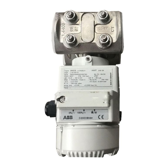
Pos: 5.17 /Überschriften/1.1/1-spaltig/S - U/Typenschild @ 0\mod_1140158480000_3101.doc @ 3216 Name plate Pos: 5.18 /Sicherheit/Druck/Druckmessumformer/Druckmessumformer 265Dx, 265Vx/Typenschilder @ 5\mod_1163757198640_3101.doc @ 48516 0045 D-32425 Minden 100%/+ 0%/- HART Type 265DS LTKA6B1 SW xx Opt. E1M1TACLH1 Bj./Yr. 20xx S/N 265DS6600018572 PED: 1G PS: 410 bar IP 67 10,5 ... - Page 11 Safety Druckfühler / Remote Seal Flanschdruckfühler - Flach DN 80 PN 16 / 40 pmax. = 40 bar Form B EN 1092 - 1 Mat. 316 L / 1.4435 Füllung/Fill. Siliconöl IB M00153 Fig. 2: Example: Additional name plate for devices with direct mount remote seals (optional) 1 Remote seal type 5 Materials that come into contact with 2 Meter size and nominal pressure...
-
Page 12: Compliance With Pressure Equipment Directive (97/23/Ec)
1 (PED: 1G). The name plate bears the following identification codes: 0045 D-32425 Minden 100%/+ 0%/- HART Type 265DS LTKA6B1 SW xx Opt. E1M1TACLH1 S/N 265DS6600018572 Bj./Yr. 20xx PED: 1G PS: 410 bar IP 67 10,5 ... -
Page 13: Operator Liability
If it is not possible to dispose of old equipment properly, ABB Service can accept and dispose of returns for a fee. Pos: 5.27 /======= Seitenumbruch ======== @ 0\mod_1126532365768_3101.doc @ 3830... -
Page 14: Transport And Storage
Safety Pos: 5.28 /Überschriften/1.1/1-spaltig/S - U/Transport und Lagerung @ 1\mod_1147676028156_3101.doc @ 10771 1.12 Transport and storage Pos: 5.29 /Transport/Druck/Allgemein/Transport und Lagerung @ 1\mod_1147677516421_3101.doc @ 10843 • After unpacking the pressure transmitter, check the device for transport damage. • Check the packaging material for accessories. •... -
Page 15: Use In Explosion-Proof Areas
Use in explosion-proof areas Pos: 7.1 /Überschriften/1/D - F/Einsatz in Ex-geschützten Bereichen @ 0\mod_1140527269500_3101.doc @ 3142 Use in explosion-proof areas Pos: 7.2 /Ex-technische Sicherheitshinweise/Druck/Druckmessumformer/Allgemein/Einführung Ex-geschützte Bereiche @ 3\mod_1157962693609_3101.doc @ 40945 According to Directive 94/9/EC (ATEX): When installing explosion-proof transmitters (electrical connection, grounding/equipotential bonding, etc.), national regulations, DIN/VDE standards, explosion protection directives, and the Ex test certificate of the device must be observed. -
Page 16: Use In Areas With Combustible Dust
Use in explosion-proof areas Pos: 7.8 /Überschriften/1.1/1-spaltig/D - F/Einsatz in Bereichen mit brennbarem Staub @ 1\mod_1147685206593_3101.doc @ 11189 Use in areas with combustible dust Pos: 7.9 /Ex-technische Sicherheitshinweise/Druck/Druckmessumformer/Allgemein/Einsatz in Bereichen mit brennbarem Staub @ 3\mod_1157963371984_3101.doc @ 41029 Installation must be performed in accordance with EN 50281-1-2. •... -
Page 17: Explosion Protection Type "Flameproof Enclosure Eex D
Use in explosion-proof areas Pos: 7.13 /Überschriften/1.1/1-spaltig/V - Z/Zünschutzart Druckfeste Kapselung EEx d @ 3\mod_1157964556390_3101.doc @ 41155 Explosion protection type "Flameproof enclosure EEx d" Pos: 7.14 /Ex-technische Sicherheitshinweise/Druck/Druckmessumformer/Allgemein/Zündschutzart Druckfeste Kapselung EEx d @ 3\mod_1157963422750_3101.doc @ 41050 Please observe the following installation information: •... -
Page 18: Explosion Protection Types "Intrinsically Safe", "Flameproof Enclosure", And "Limited Energy Equipment
Use in explosion-proof areas Pos: 7.16 /Überschriften/1.1/1-spaltig/V - Z/Zündschutzart Eigensicherheit, druckfeste Kapselung und energiebegrenzte Betriebsmittel @ 3\mod_1157964815781_3101.doc @ 41176 Explosion protection types "Intrinsically safe", "Flameproof enclosure", and "Limited energy equipment" Pos: 7.17 /Ex-technische Sicherheitshinweise/Druck/Druckmessumformer/Allgemein/Zündschutzart Eigensicherheit, druckfeste Kapselung und energiebegrenzte Betriebsmittel @ 3\mod_1157963542656_3101.doc @ 41071 Alternative certification: •... -
Page 19: Aspects Of "Ex Safety" And "Ip Protection" For Australian Applications
Use in explosion-proof areas Pos: 7.21 /Überschriften/1.1/1-spaltig/A - C/Aspekte zur Ex-Sicherheit und zum IP-Schutz für Australien @ 3\mod_1157964372968_3101.doc @ 41134 Aspects of "Ex safety" and "IP protection" for Australian applications Pos: 7.22 /Ex-technische Sicherheitshinweise/Druck/Druckmessumformer/Allgemein/Ex-Sicherheit und IP-Schutz für Australien @ 2\mod_1149838649156_3101.doc @ 29012 TestSafe certificate number ANZEx 06.3056 Protection type... - Page 20 Use in explosion-proof areas Notes • Opening the housing during operation (i.e., while the operating voltage is switched on) is not permitted. • The transmitter must be connected using a suitable cable, cable glands, or pipeline systems, which satisfy the requirements of the standards listed above and for which a separate test certificate is available.
-
Page 21: Design And Function
Design and function Pos: 9.1 /Überschriften/1/A - C/Aufbau und Funktion @ 0\mod_1129797620733_3101.doc @ 3140 Design and function Pos: 9.2 /Aufbau und Funktion/Druck/Druckmessumformer/Druckmessumformer 265Dx, 265Vx/Allgemeine Beschreibung @ 5\mod_1163759615343_3101.doc @ 48600 The 265Dx and 265Vx digital transmitters are communication-ready field devices featuring microprocessor-controlled electronics with multisensor technology. -
Page 22: Principle Of Operation And Construction
Design and function Pos: 9.4 /Überschriften/1.1/1-spaltig/A - C/Arbeitsweise und Systemaufbau @ 1\mod_1147676564281_3101.doc @ 10811 Principle of operation and construction Pos: 9.5 /Aufbau und Funktion/Druck/Druckmessumformer/Druckmessumformer 265Dx, 265Vx/Arbeitsweise und Systemaufbau @ 5\mod_1163759628015_3101.doc @ 48621 The transmitter has a modular structure and consists of measuring equipment with integrated adjustment electronics, as well as electronics with a control unit. - Page 23 Design and function M00156 Fig. 4: 265Dx transmitter 1 Measuring cell 8 Write protection 2 Overload diaphragm 9 Span 3 Process connection 10 Lower range value 4 Filling liquid 11 Output / power supply 5 pabs sensor 12 Test instrument 6 dp sensor 13 Microprocessor-based electronics 7 Isolating diaphragm...
- Page 24 Design and function It is possible to attach a tag plate in order to indicate the measuring points. The "lower range value" and "upper range value" parameters can be set using "local" buttons. If required, the buttons can be locked using the write protection switch. The transmitter may be equipped with an LCD display that can be read from the front (optional, can also be retrofitted).
-
Page 25: Mounting
Mounting Pos: 11.1 /Überschriften/1/M - O/Montage @ 0\mod_1140519732218_3101.doc @ 3159 Mounting Pos: 11.2 /Überschriften/1.1/1-spaltig/A - C/Allgemeines @ 1\mod_1147677729750_3101.doc @ 10867 General Pos: 11.3 /Montage/Druck/Druckmessumformer/Allgemein/Allgemeines @ 1\mod_1147677633390_3101.doc @ 10875 Before installing the transmitter, check whether the device design meets the requirements of the measuring point from a measurement technology and safety point of view. -
Page 26: Ip Designation
Mounting Pos: 11.5 /Überschriften/1.1/1-spaltig/G - I/IP-Kennzeichnung @ 18\mod_1203670357046_3101.doc @ 164316 IP designation Pos: 11.6 /Montage/Druck/Druckmessumformer/Druckmessumformer 265Dx, 265Vx/IP-Kennzeichnung @ 18\mod_1203670292437_3101.doc @ 164293 The housings for 265 .. / 267 .. / 269 .. transmitters are certified as conforming to protection type IP 66 / IP 67 in accordance with the IEC 529 standard. -
Page 27: Moisture
Mounting Pos: 11.10 /Überschriften/1.1/1-spaltig/D - F/Feuchtigkeit @ 1\mod_1147678490875_3101.doc @ 10923 Moisture Pos: 11.11 /Montage/Druck/Druckmessumformer/Druckmessumformer 265Dx, 265Vx/Feuchtigkeit @ 17\mod_1201093272078_3101.doc @ 153793 Use suitable cables and tighten cable glands securely. The transmitter can also be protected against the ingress of moisture by routing the connecting cable downward before securing it. This allows rain and condensation to drip down. -
Page 28: Electrical Connection
Electrical connection Pos: 13.1 /Überschriften/1/D - F/Elektrischer Anschluss @ 0\mod_1140620471687_3101.doc @ 3143 Electrical connection Pos: 13.2 /Elektrischer Anschluss/Allgemein/Hinweise zum elektrischen Anschluss @ 3\mod_1157535005078_3101.doc @ 39554 Warning - General risks Observe the applicable regulations governing electrical installation. Connections must only be established in a dead-voltage state. -
Page 29: Electrical Connection In The Cable Connection Area
Electrical connection Pos: 13.6 /Überschriften/1.1/1-spaltig/D - F/Elektrischer Anschluss im Kabelanschlussraum @ 1\mod_1147680681593_3101.doc @ 10995 Electrical connection in the cable connection area Pos: 13.7 /Elektrischer Anschluss/Druck/Druckmessumformer/Druckmessumformer 265Dx, 265Vx/Elektrischer Anschluss im Kabelanschlussraum @ 5\mod_1164013909046_3101.doc @ 48769 M00158 Fig. 7: Cable connection area (depiction of DIN housing) 1 Ground/equipotential bonding terminals 5 Test terminals for 4 ... - Page 30 Electrical connection Terminal assignment Terminals Description SIGNAL (+) and (-) Operating voltage TEST (+) and (-) Test terminals for 4 ... 20 mA (HART); not available with fieldbus transmitters M00147 Fig. 8: Connection diagram, left: 4 … 20 mA current output with HART communication protocol and power supply;...
-
Page 31: Electrical Connection With Plug
Electrical connection Pos: 13.9 /Überschriften/1.1/1-spaltig/D - F/Elektrischer Anschluss über Stecker @ 1\mod_1147680909921_3101.doc @ 11011 Electrical connection with plug Pos: 13.10 /Elektrischer Anschluss/Druck/Druckmessumformer/Druckmessumformer 265Dx, 265Vx/Elektrischer Anschluss über Stecker @ 5\mod_1164014915078_3101.doc @ 48790 7/8” M12 x 1 M00039 Fig. 9: Fieldbus connector Important Mating plugs (sockets) are not included in the delivery scope. -
Page 32: Assembling And Connecting The Socket Connector
Electrical connection Pos: 13.12 /Überschriften/1.1/1-spaltig/M - O/Montage und Anschluss der Gerätesteckdose @ 1\mod_1147681492078_3101.doc @ 11027 Assembling and connecting the socket connector Pos: 13.13 /Elektrischer Anschluss/Druck/Druckmessumformer/Allgemein/Montage und Anschluss der Gerätesteckdose @ 1\mod_1147681590765_3101.doc @ 11035 The socket connector for connecting the cable is supplied unassembled as an accessory for the transmitter. -
Page 33: Protective Conductor/Grounding
Electrical connection Pos: 13.16 /Überschriften/1.1/1-spaltig/S - U/Schutzleiteranschluss / Erdung @ 1\mod_1147681845359_3101.doc @ 11059 Protective conductor/Grounding Pos: 13.17 /Erdung/Druck/Druckmessumformer/Allgemein/Schutzleiteranschluss / Erdung @ 2\mod_1149835604343_3101.doc @ 28855 The transmitter operates within the specified levels of accuracy for common-mode voltages of up to 250 V between signal lines and housings. As a general rule, the transmitter must be supplied by a voltage source with a maximum output voltage of 60 VDC, which is safely isolated from the line supply. - Page 34 Electrical connection – – I + FSK 2600T RS 232C M00010 Fig. 12: Communication mode: Point-to-point A Pressure transmitter 1 FSK modem 2 Supply unit 2 Possible connection points for a modem between A and B 4 … 20 mA –...
-
Page 35: Connecting Cable
Electrical connection Pos: 13.23 /Überschriften/1.1/1-spaltig/A - C/Anschlusskabel @ 1\mod_1147683526078_3101.doc @ 11091 Connecting cable Pos: 13.24 /Elektrischer Anschluss/Druck/Druckmessumformer/Allgemein/Anschlusskabel @ 3\mod_1157616660609_3101.doc @ 39583 Communication between the transmitter and PC or laptop is only possible if the cabling meets the following requirements: It is recommended that shielded, twisted pair cables are used. The minimum wire diameter depends on the line length. -
Page 36: Profibus Pa Differential Pressure Transmitter
For additional information on PROFIBUS PA - including the subject "Identification numbers" - please refer "Additional notes 41/15-110" data sheet "Installation suggestions 10/63-0.40". These can be obtained from the Internet site www.abb.com; additional information is also available at www.profibus.com. Pos: 14 /======= Seitenumbruch ======== @ 0\mod_1126532365768_3101.doc @ 3830 265Dx, 265VS IM/265D/V-EN-02... -
Page 37: Commissioning
Commissioning Pos: 15.1 /Überschriften/1/G - I/Inbetriebnahme @ 0\mod_1131980668835_3101.doc @ 3150 Commissioning Pos: 15.2 /Inbetriebnahme/Druck/Druckmessumformer/Druckmessumformer 265Dx, 265Vx/Inbetriebnahme @ 5\mod_1164016655953_3101.doc @ 48853 Once the transmitter has been installed, it is put into operation by switching on the operating voltage. Check the following before switching on the operating voltage: •... -
Page 38: Output Signal
Commissioning Pos: 15.4 /Überschriften/1.1/1-spaltig/A - C/Ausgangssignal @ 1\mod_1147762481453_3101.doc @ 12415 Output signal Pos: 15.5 /Inbetriebnahme/Druck/Druckmessumformer/Druckmessumformer 265Dx, 265Vx/Ausgangssignal @ 5\mod_1164879163031_3101.doc @ 49498 If the pressure applied falls within the values indicated on the name plate, the output current will be between 4 and 20 mA. If the pressure applied falls outside the set range, the output current will be between 3.5 mA and 4 mA if the range is undershot or between 20 mA and 22.5 mA if the range is overshot (depending on the respective configuration). -
Page 39: Correcting The Lower Range Value / Zero Shift
Commissioning Pos: 15.9 /Überschriften/1.1/1-spaltig/J - L/Korrektur Messanfang / Messwerkschieflage @ 5\mod_1165484581453_3101.doc @ 50467 Correcting the lower range value / zero shift Pos: 15.10 /Inbetriebnahme/Druck/Druckmessumformer/Druckmessumformer 265Dx, 265Vx/Korrektur Messanfang / Messwerkschieflage @ 5\mod_1164017624328_3101.doc @ 48874 During installation of the transmitter, zero shifts caused by mounting (e.g., a slightly oblique mounting position due to a remote seal, etc.) may occur;... -
Page 40: Turning The Housing In Relation To The Measuring Equipment
Commissioning Pos: 15.12 /Überschriften/1.1/1-spaltig/D - F/Drehung des Gehäuses gegenüber dem Messwerk @ 5\mod_1165484889437_3101.doc @ 50488 Turning the housing in relation to the measuring equipment Pos: 15.13 /Inbetriebnahme/Druck/Druckmessumformer/Allgemein/Drehung des Gehäuses gegenüber dem Messwerk @ 2\mod_1149843345046_3101.doc @ 29138 The electronics housing can be rotated 360 ° and fixed in any position; a stop is provided to prevent it from rotating past this point. -
Page 41: Installing/Removing The Lcd Display
Commissioning Pos: 15.17 /Überschriften/1.1/1-spaltig/M - O/Montage / Demontage des LCD-Anzeigers @ 1\mod_1148889545031_3101.doc @ 18066 Installing/Removing the LCD display Pos: 15.18 /Inbetriebnahme/Druck/Druckmessumformer/Allgemein/Montage / Demontage des LCD-Anzeigers @ 4\mod_1162548621765_3101.doc @ 43744 1. Unscrew the housing cover of the electronics area (refer to the figure "Securing the housing cover"... - Page 42 Commissioning M00149 Fig. 15: Electronics area - Installing the LCD display 1 Position of the jumper or cable connector 3 10-pin terminal strip for the LCD display for an LCD display with backlighting 2 Jumper holder for an LCD display with backlighting Important The jumper (item 1) must be present if the backlighting option has not been selected for the...
-
Page 43: Securing The Housing Cover With Eex D
Commissioning Pos: 15.20 /Überschriften/1.1/1-spaltig/G - I/Gehäusedeckel sichern bei EEx d @ 2\mod_1149844920390_3101.doc @ 29222 Securing the housing cover with EEx d Pos: 15.21 /Inbetriebnahme/Druck/Druckmessumformer/Allgemein/Gehäusedeckel sichern bei EEx d @ 2\mod_1149845029468_3101.doc @ 29243 Each of the front faces of the electronics housing features a locking screw (hex-head socket screw SW 3) on the top right-hand side. -
Page 44: Operation
Operation Pos: 17.1 /Überschriften/1/A - C/Bedienung @ 1\mod_1144675546171_3101.doc @ 5944 Operation Pos: 17.2 /Überschriften/1.1/1-spaltig/A - C/Bedienung mit den Tasten am Messumformer @ 2\mod_1150094711453_3101.doc @ 29314 Operation using the buttons on the transmitter Pos: 17.3 /Bedienung/Druck/Druckmessumformer/Allgemein/Bedienung mit den Tasten am Messumformer @ 2\mod_1150095014343_3101.doc @ 29336 The control unit on the transmitter consists of 2 buttons for external setting of the "lower range value"... -
Page 45: Configuration
Configuration Pos: 19.1 /Überschriften/1/J - L/Konfiguration @ 0\mod_1140688219031_3101.doc @ 3154 Configuration Pos: 19.2 /Konfiguration, Parametrierung/Druck/Druckmessumformer/Allgemein/Sicherheitshinweis für die Konfiguration @ 1\mod_1147764542781_3101.doc @ 12488 Warning - General risks There is no protection against accidental contact when the housing cover is open. Do not touch conductive parts. Pos: 19.3 /Überschriften/1.1/1-spaltig/V - Z/Werkseinstellungen @ 1\mod_1147859886843_3101.doc @ 12602 Factory settings Pos: 19.4 /Konfiguration, Parametrierung/Druck/Druckmessumformer/Allgemein/Werkseinstellungen @ 2\mod_1150098636718_3101.doc @ 29461... -
Page 46: Transmitter With Profibus Pa Communication
Configuration 8.1.2 Transmitter with PROFIBUS PA communication Parameters Factory settings Measuring profile Pressure Physical unit mbar/bar Output scale 0 % Lower range limit (LRL) Output scale 100 % Upper range limit (URL) Output Linear Upper alarm limit Upper range limit (URL) Upper warning limit Upper range limit (URL) Lower warning limit... -
Page 47: Transmitter With Foundation Fieldbus Communication
Configuration 8.1.3 Transmitter with FOUNDATION Fieldbus communication Parameters Factory settings Measuring profile Pressure Physical unit mbar/bar Output scale 0 % Lower range limit (LRL) Output scale 100 % Upper range limit (URL) Output Linear Upper alarm limit Upper range limit (URL) Upper warning limit Upper range limit (URL) Lower warning limit... -
Page 48: Configuring The Parameters Without An Lcd Display
Configuration Pos: 19.8 /Überschriften/1.1/1-spaltig/J - L/Konfiguration der Parameter ohne LCD-Anzeiger @ 2\mod_1150099616234_3101.doc @ 29503 Configuring the parameters without an LCD display Pos: 19.9 /Konfiguration, Parametrierung/Druck/Druckmessumformer/Druckmessumformer 265Dx, 265Vx/Konfiguration der Parameter ohne LCD-Anzeiger @ 5\mod_1164019902593_3101.doc @ 48968 The "lower range value" and "span" parameters can be set directly on the transmitter using the buttons. - Page 49 Configuration Configuring the parameters 1. Apply the pressure for the "lower range value" and wait approx. 30 s until it has stabilized. 2. Press the 0 % button. This sets the output current to 4 mA. 3. Apply the pressure for the "upper range value" and wait approx. 30 s until it has stabilized. 4.
-
Page 50: Configuration With The Lcd Display
Configuration Pos: 19.11 /Überschriften/1.1/1-spaltig/J - L/Konfiguration mit dem LCD-Anzeiger @ 2\mod_1156319408468_3101.doc @ 39224 Configuration with the LCD display Pos: 19.12 /Konfiguration, Parametrierung/Druck/Druckmessumformer/Druckmessumformer 265G, 265A/Konfiguration mit dem LCD-Anzeiger @ 17\mod_1201097859906_3101.doc @ 153893 The LCD display can be used to configure the transmitter by means of the (-/+/M) buttons, as follows: Warning - Potential damage to parts Operating the control buttons with a magnetic screwdriver is not permitted. -
Page 51: Parallel Shift (Offset Shift)
Configuration 8.4.1 Parallel shift (OFFSET SHIFT) This function performs an offset shift of the characteristic so that it travels through a point specified by the user. This makes it possible to set the output signal of several measuring devices that measure the same process variable to the same value, without the need to perform calibration with applied pressure. -
Page 52: Damping (Damping)
Configuration 8.4.2 Damping (DAMPING) Pressure transmitter output signals that are noisy as a result of the process can be smoothed (damped) electrically. The additional time constant can be set between 0 s and 60 s in increments of 0.001 s. Damping does not affect the value shown on the digital display as a physical unit. -
Page 53: Layout And Contents Of The Lcd Display
Configuration Pos: 19.14 /Überschriften/1.1/1-spaltig/A - C/Aufbau und Inhalt der LCD-Anzeige @ 1\mod_1147859606453_3101.doc @ 12593 Layout and contents of the LCD display Pos: 19.15 /Konfiguration, Parametrierung/Druck/Druckmessumformer/Allgemein/Aufbau und Inhalt der LCD-Anzeige @ 2\mod_1150096660359_3101.doc @ 29419 The display is a 2-line, 7-character, 19-segment alphanumeric display with an additional bar display. - Page 54 Configuration Second line In the second line, the unit is displayed in the last five columns. The first column shows the symbols listed below. If necessary, these symbols can also be displayed one after the other. The symbol displayed is changed in cycles of one second. Explanation of the symbols Display for Symbol...
-
Page 55: Menu Structure
Configuration How the percentage value is shown on the LCD display Position Display 1st line Percentage value, limits: -25 … 125 %, 2 decimal places 2nd line 1st digit: Transmission function (see previous table) 2nd digit: Write protection (see previous table) 7th digit: 2 % increments, from -2 …... - Page 56 Configuration Pos: 19.19 /Konfiguration, Parametrierung/Druck/Druckmessumformer/Druckmessumformer 265Dx, 265Vx/Menüstruktur - Deutsch @ 5\mod_1164095578125_3101.doc @ 48993 The menu is called up using the mode button "M". Main menu Submenu (other parameters/explanations) The numbers EXIT displayed inversely VIEW Output signal in physical unit ) specify the (Temporary display of (265Dx: Current measured value for differential pressure, code for the display...
-
Page 57: Menu-Controlled Pressure Transmitter Programming
Configuration Pos: 19.21 /Überschriften/1.1/1-spaltig/M - O/Menügesteuerte Programmierung des Druckmessumformers @ 2\mod_1150101484046_3101.doc @ 29545 Menu-controlled pressure transmitter programming Pos: 19.22 /Konfiguration, Parametrierung/Druck/Druckmessumformer/Allgemein/Menügesteuerte Programmierung des Druckmessumformers @ 17\mod_1201185787890_3101.doc @ 154202 Function Description Start Menu-controlled programming is started with the mode button "M". The next menu item is called up by pressing the "+"... -
Page 58: Parameter Description
Configuration Pos: 19.24 /Überschriften/1.1.1/1-spaltig/Parameterbeschreibung @ 1\mod_1147935919250_3101.doc @ 12649 8.6.1 Parameter description Pos: 19.25 /Konfiguration, Parametrierung/Druck/Druckmessumformer/Druckmessumformer 265Dx, 265Vx/Parameterbeschreibung @ 5\mod_1164102970328_3101.doc @ 49035 8.6.1.1 "VIEW" parameter Temporary display of display values 1 to 9 (setting is volatile) The following measured values can be set: •... - Page 59 Configuration 8.6.1.7 (Damping) parameter Setting for an additional time constant, between 0 s and 60 s, in increments of 0.001 s. 8.6.1.8 "ALARM CURRENT" parameter Not with fieldbus transmitters 8.6.1.9 "DISPLAY" parameter Selection (non-volatile) for LCD display values 1, 2, or 3 (permanent display) The following measured values can be set: •...
-
Page 60: Configuration With The Pc/Laptop Or Handheld Terminal
Configuration Pos: 19.27 /Überschriften/1.1/1-spaltig/J - L/Konfiguration mit PC / Laptop oder Handheld-Terminal @ 1\mod_1147935987375_3101.doc @ 12658 Configuration with the PC/laptop or handheld terminal Pos: 19.28 /Konfiguration, Parametrierung/Druck/Druckmessumformer/Druckmessumformer 265Dx, 265Vx/Konfiguration mit PC / Laptop oder Handheld-Terminal @ 17\mod_1201100306375_3101.doc @ 153918 A graphical user interface (DTM) is required for configuration of the transmitter via PC or laptop. For operating instructions, please refer to the software description. - Page 61 Configuration min 250 W – – I + FSK Automation Products Automation Products M00029 Fig. 22: Connection examples with communication resistor in the connection line A Transmitter B Supply unit (communication resistor not provided in supply unit) For additional information, refer to the operating instructions included with the handheld terminal.
-
Page 62: Configuration With The Graphical User Interface (Dtm)
Configuration Pos: 19.30 /Überschriften/1.1/1-spaltig/J - L/Konfiguration über die graphische Bedienoberfläche (DTM) @ 1\mod_1147936088578_3101.doc @ 12667 Configuration with the graphical user interface (DTM) Pos: 19.31 /Konfiguration, Parametrierung/Druck/Druckmessumformer/Druckmessumformer 265Dx, 265Vx/Konfiguration über die graphische Bedienoberfläche (DTM) @ 17\mod_1201100543250_3101.doc @ 153943 8.8.1 System requirements •... -
Page 63: Setting The Damping Value
Configuration 8.8.2 Setting the damping value Menu path: "Configure_Differential Pressure Measurement_Output" Enter the desired value in the "Damping" line of the "Output parameter" field. 8.8.3 Correcting the zero shift / oblique sensor Menu path: "Configure_Differential Pressure Measurement_Process Variable" Press the "Adjust" button in the "Oblique sensor" field. Calibration is performed immediately and saved to the transmitter's non-volatile memory. -
Page 64: Explosion Protection Data
Explosion protection data Pos: 21.1 /Überschriften/1/D - F/Ex-technische Daten @ 0\mod_1132304633775_3101.doc @ 3145 Explosion protection data Pos: 21.2 /Überschriften/1.1/1-spaltig/D - F/Explosionsgefährdete Atmosphären @ 2\mod_1149586014500_3101.doc @ 28190 Potentially explosive atmospheres Pos: 21.3 /==== Wechsel ein- auf zweispaltig ==== @ 0\mod_1130421847171_3101.doc @ 3828 Change from one to two columns Pos: 21.4 /Technische Daten / Datenblatt/Druck/Druckmessumformer/265VS/Explosionsgefährdete Atmosphären/Explosionsgefährdete Atmosphären @ 20\mod_1208413159843_3101.doc @ 180768 Permissible ambient temperature range depending on temperature... - Page 65 Explosion protection data Transmitter with "Intrinsically safe EEx ia" type of explosion Fieldbus transmitter (PROFIBUS PA / FOUNDATION Fieldbus): protection in accordance with Directive 94/9/EC (ATEX), or Intrinsically safe protection : Class I, II, and III; Division 1; "Flameproof EEx d" type of explosion protection in accordance Groups A, B, C, D, E, F, G;...
- Page 66 Explosion protection data Transmitter with "Flameproof Ex d" type of explosion protection Fieldbus transmitter (PROFIBUS PA / FOUNDATION Fieldbus) Transmitter with 4 … 20 mA output signal, HART communication, Identification: Ex ia IIB/IIC T4 … T6 and fieldbus transmitter (PROFIBUS PA / FOUNDATION Fieldbus, Modbus): Permissible ambient temperature range depending on temperature class:...
-
Page 67: Technical Data
Technical data Pos: 23.1 /Überschriften/1/S - U/Technische Daten @ 0\mod_1132904574837_3101.doc @ 3169 10 Technical data Pos: 23.2 /Überschriften/1.1/2-spaltig/D - F/Funktionale Spezifikation @ 1\mod_1148976354843_3101.doc @ 27494 10.1 Functional specifications Pos: 23.3 /==== Wechsel ein- auf zweispaltig ==== @ 0\mod_1130421847171_3101.doc @ 3828 Change from one to two columns Pos: 23.4 /Technische Daten / Datenblatt/Druck/Druckmessumformer/265Dx, 265Vx/Messbereich und Messspannengrenzwerte @ 5\mod_1164182285812_3101.doc @ 49207 Measured variable... -
Page 68: Operating Limits
Technical data Pos: 23.7 /Überschriften/1.1/2-spaltig/A - C/Betriebsgrenzwerte @ 1\mod_1148976534187_3101.doc @ 27515 10.2 Operating limits Pos: 23.8 /Überschriften/1.1.1/1-spaltig/Temperaturgrenzen in °C (°F) @ 5\mod_1165391440171_3101.doc @ 50274 10.2.1 Temperature limits in °C (°F) Pos: 23.9 /==== Wechsel ein- auf zweispaltig ==== @ 0\mod_1130421847171_3101.doc @ 3828 Change from one to two columns Pos: 23.10 /Technische Daten / Datenblatt/Druck/Druckmessumformer/265Dx, 265Vx/Temperaturgrenzen @ 5\mod_1164184292718_3101.doc @ 49228 Process temperature range... -
Page 69: Environmental Limits
Technical data Static pressure 265Vx transmitter Static pressure The 265Dx transmitter operates within the specifications with the Absolute 0 following limits: up to 265Dx transmitter Static pressure 16 MPa, 160 bar, 2,320 psi, or Sensor code F ... N 3.5 kPa abs., 35 mbar abs., 0.5 psia 25 MPa, 250 bar, 3,625 psi, or Silicone oil for sensor up to... -
Page 70: Electrical Data And Options
Technical data Pos: 23.26 /Überschriften/1.1/2-spaltig/D - F/Elektrische Daten und Optionen @ 1\mod_1148983389609_3101.doc @ 27580 10.4 Electrical data and options Pos: 23.27 /Überschriften/1.1.1/1-spaltig/HART-Digitalkommunikation und 4 ... 20 mA Ausgangsstrom @ 5\mod_1165391958890_3101.doc @ 50316 10.4.1 HART digital communication and 4 ... 20 mA output current Pos: 23.28 /==== Wechsel ein- auf zweispaltig ==== @ 0\mod_1130421847171_3101.doc @ 3828 Change from one to two columns Pos: 23.29 /Technische Daten / Datenblatt/Druck/Druckmessumformer/265Dx, 265Vx/HART-Digitalkommunikation @ 5\mod_1164188320406_3101.doc @ 49249... -
Page 71: Profibus Pa Output
Technical data Pos: 23.32 /Überschriften/1.1.1/1-spaltig/PROFIBUS PA-Ausgang @ 5\mod_1165392154421_3101.doc @ 50337 10.4.2 PROFIBUS PA output Pos: 23.33 /==== Wechsel ein- auf zweispaltig ==== @ 0\mod_1130421847171_3101.doc @ 3828 Change from one to two columns Pos: 23.34 /Technische Daten / Datenblatt/Druck/Druckmessumformer/265Dx, 265Vx/PROFIBUS PA-Ausgang @ 5\mod_1164188760546_3101.doc @ 49270 Output cycle time Model 40 ms... -
Page 72: Measuring Accuracy
Technical data Pos: 23.42 /Überschriften/1.1/2-spaltig/M - O/Messgenauigkeit @ 1\mod_1148983730859_3101.doc @ 27601 10.5 Measuring accuracy Pos: 23.43 /==== Wechsel ein- auf zweispaltig ==== @ 0\mod_1130421847171_3101.doc @ 3828 Change from one to two columns Pos: 23.44 /Technische Daten / Datenblatt/Druck/Druckmessumformer/265Dx, 265Vx/Messgenauigkeit @ 5\mod_1164189140312_3101.doc @ 49312 Dynamic behavior (according to IEC 61298-1) Reference conditions acc. -
Page 73: Operating Influences 265Vx
Technical data Pos: 23.51 /Technische Daten / Datenblatt/Druck/Druckmessumformer/265Dx, 265Vx/Betriebseinflüsse 265Vx @ 17\mod_1201165220734_3101.doc @ 153973 Installation position 10.6.2 Operating influences 265Vx Rotations in the plane of the diaphragm have a negligible effect. A tilt from the vertical causes a zero shift of sin a x 0.35 kPa (3.5 mbar, 1.4 Thermal change in ambient temperature on the zero signal and in H O) of the upper range limit, which can be corrected using an... -
Page 74: Technical Specification
Technical data Pos: 23.54 /Überschriften/1.1/2-spaltig/S - U/Technische Spezifikation @ 1\mod_1149057925953_3101.doc @ 27643 10.7 Technical specification Pos: 23.55 /==== Wechsel ein- auf zweispaltig ==== @ 0\mod_1130421847171_3101.doc @ 3828 Change from one to two columns Pos: 23.56 /Technische Daten / Datenblatt/Druck/Druckmessumformer/265Dx, 265Vx/Technische Spezifikation @ 17\mod_1201166249781_3101.doc @ 153997 Optional accessories Important Mounting bracket... -
Page 75: Mounting Dimensions (Not Design Data)
Technical data Pos: 23.59 /Überschriften/1.1/1-spaltig/M - O/Montageabmessungen (keine Konstruktionsangaben) @ 1\mod_1149058512625_3101.doc @ 27748 10.8 Mounting dimensions (not design data) Pos: 23.60 /Überschriften/1.1.1/1-spaltig/Differenzdruckmessumformer mit Barrel-Gehäuse @ 17\mod_1201169114234_3101.doc @ 154052 10.8.1 Differential pressure transmitter with barrel housing Pos: 23.61 /Technische Daten / Datenblatt/Druck/Druckmessumformer/Druckmessumformer 265Dx, 265Vx/Maßzeichnungen/Messumformer mit Barrel-Gehäuse @ 5\mod_1165223965343_3101.doc @ 50073 114 (4.49) 23 (0.91) 9 (0.35) -
Page 76: Differential Pressure Transmitter With Din Housing
Technical data Pos: 23.63 /Überschriften/1.1.1/1-spaltig/Differenzdruckmessumformer mit DIN-Gehäuse @ 17\mod_1201169607484_3101.doc @ 154077 10.8.2 Differential pressure transmitter with DIN housing Pos: 23.64 /Technische Daten / Datenblatt/Druck/Druckmessumformer/Druckmessumformer 265Dx, 265Vx/Maßzeichnungen/Messumformer mit DIN-Gehäuse @ 5\mod_1165224783078_3101.doc @ 50094 70 (2.76) (1.69) 61 (2.40) 96 (3.78) 54 (2.13) 20 (0.79) 107 (4.21) 138 (5.43) -
Page 77: Mounting Options With Bracket
Mounting options with bracket Pos: 23.66 /Überschriften/1/M - O/Montagemöglichkeiten mit Befestigungswinkel @ 3\mod_1158653576343_3101.doc @ 41912 11 Mounting options with bracket Pos: 23.67 /Technische Daten / Datenblatt/Druck/Druckmessumformer/Allgemein/Maßzeichnungen/Montagemöglichkeiten mit Befestigungswinkel @ 7\mod_1159171943671_3101.doc @ 42705 Ø 11 (0.43) 60 (2.36) 135.5 (5.33) 72 (2.83) 56 (2.20) 110 (4.33) 214 (8.43) -
Page 78: Maintenance / Repair
Before you return the device, please clean it and pack it safely and securely. When ordering spare parts or replacement devices, please quote the serial number (S/N) of the original device as well as the year of manufacture (Yr.). Address ABB Automation GmbH - Service Instruments - Schillerstr. 72 D-32425 Minden... -
Page 79: Removal
Maintenance / Repair Pos: 25.4 /Überschriften/1.1/1-spaltig/D - F/Demontage @ 5\mod_1162976675906_3101.doc @ 45386 12.1 Removal Pos: 25.5 /Wartung / Reparatur/Druck/Druckmessumformer/Allgemein/Demontagehinweise @ 1\mod_1147936535984_3101.doc @ 12694 Warning - General risks Before removing or disassembling the device, check for hazardous process conditions such as pressure on the device, high temperatures, aggressive or toxic media, and so on. Read the instructions in the sections "Safety"... - Page 80 Maintenance / Repair 265Dx transmitter with measuring range of 10 mbar: Use a torque wrench to tighten the process flange screws, working on them alternately and in a crosswise manner. Tightening torque: M = 10 Nm (1.0 kpm). Check the tightness of the connection: Apply a maximum pressure of 1.3 x PN (nominal pressure) to the 265Dx;...
-
Page 81: Removing The Electronics
Maintenance / Repair Pos: 25.8 /Wartung / Reparatur/Druck/Druckmessumformer/Druckmessumformer 265Dx, 265Vx/Demontage der Elektronik @ 17\mod_1201172491953_3101.doc @ 154127 12.1.2 Removing the electronics If the electronics housing needs to be unscrewed from the measuring equipment/measuring cell, the electronics must first be removed from their housing to prevent them from being damaged. -
Page 82: Appendix
− Conforms to EMC Directive 89/336/EEC − Conforms to Low Voltage Directive 73/23/EEC − Conforms to Pressure Equipment Directive (PED) 97/23/EC By placing the CE mark on its devices, ABB Automation Products GmbH declares that they conform to these directives. Explosion This symbol indicates devices with an explosion-proof design. - Page 83 Appendix Pos: 27.6 /Anhang/Druck/Allgemein/EG-Konformitätserklärung @ 23\mod_1226502446812_3101.doc @ 224503 Pos: 27.7 /======= Seitenumbruch ======== @ 0\mod_1126532365768_3101.doc @ 3830 IM/265D/V-EN-02 265Dx, 265VS...
- Page 84 Appendix Pos: 27.8 /Anhang/Allgemein/Rücksendeformular @ 0\mod_1132757486454_3101.doc @ 3820 Statement on the contamination of devices and components Repair and/or maintenance work will only be performed on devices and components if a statement form has been completed and submitted. Otherwise, the device/component returned may be rejected. This statement form may only be completed and signed by authorized specialist personnel employed by the operator.
-
Page 85: Index
Index Pos: 29 /Überschriften/1/G - I/Index @ 0\mod_1138787046328_3101.doc @ 3151 14 Index Pos: 30 /==== Wechsel ein- auf zweispaltig ==== @ 0\mod_1130421847171_3101.doc @ 3828 Change from one to two columns Pos: 31 /Inhaltsverzeichnis/Index @ 0\mod_1138784494500_3101.doc @ 3128 Explosion protection type........15, 17 Appendix ..............83 Explosion protection types........18 Approvals and certifications........83... - Page 86 Index Operator liability ............13 Safety information for electrical installation .....14 Output signal............39 Securing the housing cover with EEx d ....44 Parameter description..........59 Technical data............68 Plates and symbols............9 Technical limit values..........8 Potentially explosive atmospheres ......65 Technical specification..........75 Pressure limits ............69 Temperature limits in °C (°F) ........69 Principle of operation and construction ....22 Transport and storage ..........14 PROFIBUS PA differential pressure transmitter..37...
- Page 88 ABB has Sales & Customer Support The Company’s policy is one of continuous product expertise in over 100 countries worldwide. improvement and the right is reserved to modify the information contained herein without notice. www.abb.com/pressure Printed in the Fed. Rep. of Germany (11.2008) ©...
Need help?
Do you have a question about the 265DS and is the answer not in the manual?
Questions and answers