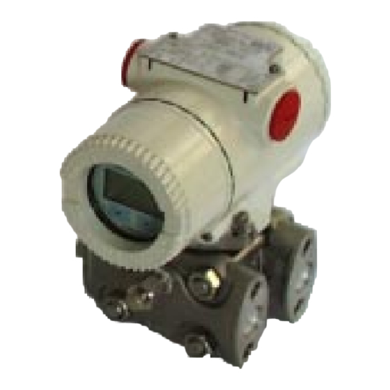
ABB 2600T Series Instructions For Installation And Commissioning
Pressure transmitters
Hide thumbs
Also See for 2600T Series:
- Instruction manual (136 pages) ,
- Operating instructions manual (96 pages) ,
- Operating instruction (84 pages)

Related Manuals for ABB 2600T Series


Summary of Contents for ABB 2600T Series
- Page 1 Field Instruction for installation and commissioning 2600T Series Pressure Transmitters PED/262_4D_9 Models 264B/D/V/P - 1 -...
- Page 2 Cert. No. Q5907 As a part of ABB, a world leader in process automation technology, we offer customers application expertise, service and support worldwide. ISO 9001: 2000 We are committed to teamwork, high quality manufacturing, advanced technology and unrivalled service and support.
-
Page 3: Table Of Contents
4.2 ELECTRICAL CONNECTIONS ...... 16 manuals are available also in electronic format on www.abb.com 4.3 SUPPLY WIRING REQUIREMENTS ..... 17 searching for the keyword “IM/*26*” or from local ABB representatives. 5. PHASE 4 - TRANSMITTER OPERATION 5.1 FLOW MEASUREMENT ........ 18 5.2 LEVEL MEASUREMENT ........ -
Page 4: Phase 1 - Preliminary Checks
PHASE 1 - PRELIMINARY CHECKS PRELIMINARY CHECKS check that all the parameters listed on this label (or on the certificates enclosed with the transmitter) are in accordance Before mounting the transmitter, check the compatibility with with the requirements of the area where the transmitter is going the following measurement and safety requirements: to be installed. -
Page 5: Pressure And Temperature Limits
- 230psi for ASME CL150 flange further details (the manual is available at www.abb.com inserting - 600psi for ASME CL300 flange in the “search” tool the keyword “IM/26X”) or from local ABB The pressure limit decreases with increasing temperature representatives. -
Page 6: Environmetal Limits
Complies with EN 50081–1 for emission and EN 50082–2 for A fluid / material compatibility table is available at www.abb.com immunity requirements and test; (inserting in the “search” tool the keyword “TB/COR”) or from Radiated electromagnetic immunity level: 30V/m (according to local ABB representatives. -
Page 7: Phase 2 - Transmitter Installation
PHASE 2 - TRANSMITTER INSTALLATION 3. TRANSMITTER INSTALLATION The following examples are standard mounting locations for instrumentation suitable for these main types of applications: TRANSMITTER LOCATION Orifice plate filling tees Flow gate valves vent valve 3-valve manifold Flow measurement with clean liquids or steam (condensable vapor) 1. - Page 8 PHASE 2 - TRANSMITTER INSTALLATION drain valve 3-valve 3-valve manifold manifold gate valves Flow Flow Flow measurement with gas or liquids with solids in suspension 1. Place the taps to the top or side of the line. 2. Mount the transmitter above the taps. Max.
- Page 9 PHASE 2 - TRANSMITTER INSTALLATION Level measurement with closed tanks and non condensable fluids (dry leg) Gate 1. Mount the transmitter at the same height or below the Max. Level valve lowest level to be measured. 2. Connect the + (H) side of the transmitter to the bottom of the tank.
- Page 10 PHASE 2 - TRANSMITTER INSTALLATION Pressure or absolute pressure measurement of a tank 1. Select a tap in the upper part of the tank. 2. Mount the transmitter above the elevation of the process tap. 3. Connect the + (H) side of the transmitter to the tank. gate valve Pressure or absolute pressure measurement of a liquid in a pipe...
- Page 11 PHASE 2 - TRANSMITTER INSTALLATION Pressure or absolute pressure measurement of a condensable vapor in a pipe filling 1. Place the tap at the side of the line. 2. Mount the transmitter below the tap. gate 3. Connect the + (H) side of the transmitter to the pipe. valve 4.
-
Page 12: Transmitter Mounting
PHASE 2 - TRANSMITTER INSTALLATION In addition, consider the need for a testing or calibration input, TRANSMITTER MOUNTING and provide space for the housing covers to be removed for electrical wiring and maintenance. Orient the process flanges to enable process connections to be made. - Page 13 PHASE 2 - TRANSMITTER INSTALLATION Traditional (Barrel) housing vertical mounting with bracket for vertical or horizontal pipe (option B1 and B2). DIN housing vertical mounting with bracket for vertical or horizontal pipe (option B1 and B2). - 13 -...
-
Page 14: Process Connections
PHASE 2 - TRANSMITTER INSTALLATION Traditional (Barrel) Housing horizontal mounting with flat bracket type (option B5, this is the only bracket suitable for units quipped with Stainless Steel housing). Mounting to vertical or horizontal pipe Traditional (Barrel) Housing horizontal mounting with wall mounting bracket (option B3 and B4) PROCESS CONNECTIONS Housing Rotation Process connections on the transmitter flange are 1/4 - 18 NPT, with a centers distance of 54mm (2.13in) between the... -
Page 15: Rotation
PHASE 2 - TRANSMITTER INSTALLATION ROTATION Housing Rotation To improve field access to wiring or the readability of the optional LCD meter it is possible to rotate the Housing and the Meters or the Integral display. Housing Rotation Unlock the housing rotation set screw by turning it 1 turn (use the 3 mm Allen key supplied with the instrument) Turn the housing clock wise or counterclockwise up to 180°... -
Page 16: Phase 3 - Transmitter Wiring
PHASE 3 - TRANSMITTER WIRING 4. TRANSMITTER WIRING 5. Run the cable through the cable gland and the open port. 6. Connect the positive lead to the + terminal, and the negative PROTECTIVE GROUNDING lead to the – terminal. All transmitters are supplied with an external ground connection ✶... -
Page 17: Supply Wiring Requirements
In case of FF or Profibus connections see the relevant diagram. For further information find the relevant instruction manuals searching for the keyword "IM/*26*" on www.abb.com or from local ABB representatives. cover locking screw SUPPLY WIRING REQUIREMENTS For signal/power connection use twisted, stranded pairs of wiring no 18 to 22 AWG / 0.8 to 0.35mm... -
Page 18: Phase 4 - Transmitter Operation
PHASE 4 - TRANSMITTER OPERATION 5. TRANSMITTER OPERATION Use the following step to adjust the transmitter zero. FLOW MEASUREMENT 1. The process fluid must enter the transmitter primary: 1 2 3 4 5 6 a. Close low pressure (B) and high pressure (A) valves (fig. -
Page 19: Level Measurement
PHASE 4 - TRANSMITTER OPERATION 3. After venting or draining, output should be 4 mA dc. If not: a. Rotate the nameplate to get access to the external push buttons. b. Push the zero (Z) button on top of the transmitter (figure 5.3) for at least 2 seconds. -
Page 20: Pressure Measurements
PHASE 4 - TRANSMITTER OPERATION PRESSURE MEASUREMENTS b. Push the zero (Z) button on top of the transmitter (figure 1. Slowly open the gate valve to admit process fluid to primary 5.3) for at least 2 seconds. of side H. c. - Page 21 - 21 -...
- Page 22 - 22 -...
- Page 23 Service and Repair Centre. – Food & Beverage – Manufacturing Italy – Metals and Minerals – Oil, Gas & Petrochemical ABB S.p.A. Business Unit Measurement Products – Pulp and Paper Tel: +39 0344 58111 Drives and Motors Fax: +39 0344 56278 •...
- Page 24 The Company’s policy is one of continuous product ABB has Sales & Customer Support improvement and the right is reserved to modify the expertise in over 100 countries worldwide information contained herein without notice. Printed in Italy (03.08) www.abb.com/instrumentation © ABB 2012 ABB Ltd ABB S.p.A.