Toro 22318 Operator's Manual
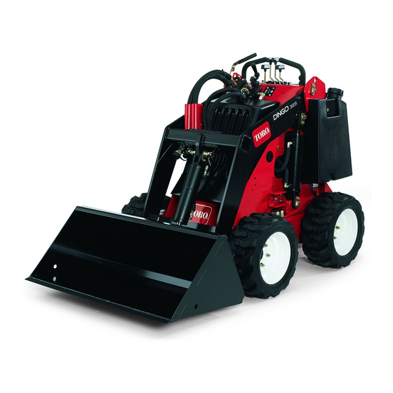
Compact utility loader
Hide thumbs
Also See for 22318:
- Operator's manual (36 pages) ,
- Service manual (602 pages) ,
- Operator's manual (13 pages)
Table of Contents
Advertisement
Quick Links
Download this manual
See also:
Service Manual
Advertisement
Table of Contents

Related Manuals for Toro 22318


Summary of Contents for Toro 22318
- Page 1 Form No. 3359-248 Rev A 323 Compact Utility Loader Model No. 22318—Serial No. 280000001 and Up To register your product or download an Operator's Manual or Parts Catalog at no charge, go to www.Toro.com. Original Instructions (EN)
-
Page 2: Introduction
Whenever you need service, genuine Toro parts, or additional information, contact an Authorized Service There may be buried power, gas, and/or Dealer or Toro Customer Service and have the model telephone lines in the work area. Shock or and serial numbers of your product ready. Figure 1 explosion may occur if you dig into them. -
Page 3: Table Of Contents
This manual uses 2 other words to highlight information. Replacing the Battery.......... 27 Important calls attention to special mechanical Servicing the Battery........... 28 information and Note emphasizes general information Hydraulic System Maintenance ....... 30 worthy of special attention. Replacing the Hydraulic Filter ......30 Changing the Hydraulic Fluid ...... -
Page 4: Safety
Safety • Inspect the area where the equipment is to be used and remove all objects such as rocks, toys, and wire which can be thrown by the machine. Improper use or maintenance by the operator • Use extra care when handling gasoline and other or owner can result in injury. - Page 5 • Do not touch parts which may be hot from grass can hide obstacles. operation. Allow them to cool before attempting to • Use only Toro-approved attachments. Attachments maintain, adjust, or service. can change the stability and the operating • Check for overhead clearances (i.e. branches, characteristics of the traction unit.
- Page 6 • Let the engine cool before storing and do not store object. Make any necessary repairs before restarting. near flame. • Use only genuine Toro replacement parts to ensure • Do not store fuel near flames or drain indoors. that original standards are maintained.
-
Page 7: Slope Indicator
Slope Indicator... -
Page 8: Safety And Instructional Decals
Safety and Instructional Decals Safety decals and instructions are easily visible to the operator and are located near any area of potential danger. Replace any decal that is damaged or lost. 98-9051 108-9732 98-4682 108-9716 100-6141 1. Fast 4. Slow 2. - Page 9 Battery Symbols Some or all of these symbols are on your battery 98-8219 1. Explosion hazard 6. Keep bystanders a safe 1. Fast 3. Slow distance from the battery. 2. Throttle 2. No fire, open flame, or 7. Wear eye protection; smoking.
-
Page 10: Setup
Setup Battery terminals or metal tools could short Installing the Valve Lever against metal components, causing sparks. Sparks can cause the battery gasses to explode, 1. Remove and discard the nut securing the bolt and resulting in personal injury. lock washer to the speed selector lever. •... -
Page 11: Product Overview
Product Overview G005287 Figure 5 1. Mount plate 6. Fuel tank 11. Counterweight 16. Lift points 2. Tilt cylinder 7. Lift cylinder 12. Engine 17. Handles 3. Auxiliary hydraulic couplers 8. Tow valve 13. Air cleaner 4. Loader arms 9. Wheel 14. - Page 12 Note: The farther you move the traction control levers in either direction, the faster the traction unit will move in that direction. If you move the speed selector lever while the traction unit is in motion, the traction unit will •...
-
Page 13: Specifications
Operating capacity (with 200 lb operator, 515 lb (234 Kg) Authorized Service Dealer or Distributor or go to the standard bucket, and without the www.Toro.com for a list of all approved attachments counterweight) and accessories. Tipping capacity (with 200 lb operator,... -
Page 14: Operation
Operation Note: Determine the left and right sides of the machine from the normal operating position. Important: Before operating, check the fuel and oil level, remove debris from the traction unit, and check the tire pressure. Also, ensure that the area is clear of people and debris. You should also know and have marked the locations of all utility lines. -
Page 15: Checking The Engine Oil Level
Use unleaded gasoline (87 pump octane minimum). Leaded, regular gasoline may be used if unleaded is not available. Important: Do not use methanol, gasoline containing methanol, or gasohol containing more than 10% ethanol because the fuel system could be damaged. Do not mix oil with gasoline. Using Stabilizer/Conditioner Figure 7 Use a fuel stabilizer/conditioner in the traction unit to... -
Page 16: Checking The Hydraulic Fluid Level
Note: Use a lower tire pressure (15 psi) when operating electrical system and hydraulic valves or deplete grease. in sandy soil conditions to provide better traction in the loose soil. 6. Remove and store the cylinder locks and lower the loader arms. -
Page 17: Driving The Traction Unit
the middle throttle position for 2 to 5 minutes before moving the throttle to fast (rabbit). A child or untrained bystander could attempt to Note: If outdoor temperature is below freezing, operate the traction unit and be injured. store the traction unit in a garage to keep it warmer and aid in starting. -
Page 18: Using The Cylinder Locks
3. Hairpin cotter Installing an Attachment 6. With the engine off, lower the loader arms. Important: Use only Toro-approved attachments. Attachments can change the stability and the operating characteristics of the traction unit. The warranty of the traction unit may be voided if used with unapproved attachments. - Page 19 Figure 13 1. Mount plate 2. Receiver plate 5. Raise the loader arms while tilting back the mount plate at the same time. Important: The attachment should be raised enough to clear the ground, and the mount plate should be tilted all the way back. 6.
-
Page 20: Securing The Traction Unit For Transport
Important: Connect the attachment 6. Push the attachment male connector into the female connector on the traction unit. hoses together to prevent hydraulic system contamination during storage. Note: When you connect the attachment male 6. Install the protective covers onto the hydraulic connector first, you will relieve any pressure built up couplers on the traction unit. -
Page 21: Maintenance
Maintenance Note: Determine the left and right sides of the machine from the normal operating position. Recommended Maintenance Schedule(s) Maintenance Service Maintenance Procedure Interval • Replace the hydraulic filter. After the first 8 hours • Torque the wheel lug nuts to 50 ft-lb (68 N-m). •... -
Page 22: Premaintenance Procedures
Premaintenance Lubrication Procedures Greasing the Traction Unit Removing/Installing the Hood Service Interval: Before each use or daily (Grease immediately after every washing) Removing the Hood Grease Type: General-purpose grease. 1. Lower the loader arms and stop the engine. Remove Before performing many maintenance procedures, you the key. -
Page 23: Engine Maintenance
Engine Maintenance Servicing the Air Cleaner Service Interval: Every 200 hours—Replace the primary filter. (Service more frequently if conditions are extremely dusty or sandy.) Yearly—Replace the safety (secondary) air filter. (Service Figure 18 more frequently if conditions are extremely dusty or sandy.) Important: Do not clean the filters. -
Page 24: Changing The Engine Oil And Filter
Changing the Engine Oil and 6. Gently slide the primary filter out of the air cleaner body and discard it (Figure 19). Avoid knocking the Filter filter into the side of the body. Service Interval: After the first 50 hours 7. -
Page 25: Servicing The Spark Plugs
14. Slowly add additional oil to bring the level to the F (full) mark on the dipstick. 15. Replace the fill cap. Servicing the Spark Plugs Service Interval: Every 200 hours—Check the spark plugs. Ensure that the air gap between the center and side electrodes is correct before installing each spark plug. -
Page 26: Fuel System Maintenance
Fuel System Maintenance Changing the Fuel Filter Service Interval: Yearly Important: Never install a dirty filter. 1. Lower the loader arms, stop the engine, and remove Figure 24 the key. 1. Center electrode insulator 3. Air gap (not to scale) 2. -
Page 27: Electrical System Maintenance
Wash hands after handling. Replacing the Battery When the battery no longer holds a charge, replace it. Important: Use only a genuine Toro replacement battery. Figure 26 1. Fuel valve, open 2. Fuel valve, closed 1. -
Page 28: Servicing The Battery
Servicing the Battery Service Interval: Every 100 hours—Check the battery Battery terminals or metal tools could short electrolyte level (replacement battery against metal components, causing sparks. only). Sparks can cause the battery gasses to explode, resulting in personal injury. Every 100 hours—Check the battery cable connections. - Page 29 Battery electrolyte contains sulfuric acid which is a deadly poison and causes severe burns. • Do not drink electrolyte and avoid contact with skin, eyes or clothing. Wear safety glasses to shield your eyes and rubber gloves to protect your hands. •...
-
Page 30: Hydraulic System Maintenance
Hydraulic System Maintenance Hydraulic fluid escaping under pressure can penetrate skin and cause injury. Fluid injected into the skin must be surgically removed within Replacing the Hydraulic Filter a few hours by a doctor familiar with this form of injury or gangrene may result. Service Interval: After the first 8 hours •... -
Page 31: Checking The Hydraulic Lines
Checking the Hydraulic Lines Storage Service Interval: Every 25 hours—Check the hydraulic 1. Lower the loader arms, stop the engine, and remove lines for leaks, loose fittings, kinked the key. lines, loose mounting supports, wear, 2. Remove dirt and grime from the external parts of the weather, and chemical deterioration. - Page 32 F. Start and run the engine until it will not start again. G. Dispose of fuel properly. Recycle as per local codes. Important: Do not store stabilizer/conditioned gasoline over 90 days. 13. Check and tighten all bolts, nuts, and screws. Repair or replace any part that is damaged or defective.
-
Page 33: Troubleshooting
Troubleshooting Problem Possible Cause Corrective Action The starter does not crank 1. The auxiliary hydraulics lever is not in 1. Move the lever to the neutral position. the neutral position. 2. The battery is discharged. 2. Charge the battery or replace it. 3. -
Page 34: Schematics
Schematics Electrical Schematic (Rev. A) - Page 35 Hydraulic Schematic (Rev. A)
- Page 36 Countries Other than the United States or Canada Customers who have purchased Toro products exported from the United States or Canada should contact their Toro Distributor (Dealer) to obtain guaran- tee policies for your country, province, or state. If for any reason you are dissatisfied with your Distributor’s service or have difficulty obtaining guarantee information, contact the Toro importer.