Honeywell 2020 User Manual
Cordless system
Hide thumbs
Also See for 2020:
- User manual (284 pages) ,
- User manual (192 pages) ,
- User manual (95 pages)
Table of Contents
Advertisement
Quick Links
Advertisement
Table of Contents

Related Manuals for Honeywell 2020


Summary of Contents for Honeywell 2020
- Page 1 2020/3820/3820i Cordless System User’s Guide ™...
- Page 2 The information in this publication does not represent a commitment on the part of Honeywell. Honeywell shall not be liable for technical or editorial errors or omissions con- tained herein; nor for incidental or consequential damages resulting from the furnishing, performance, or use of this material.
-
Page 3: Industry Canada
2. This device must accept any interference received, including interference that may cause undesired operation. Caution: Any changes or modifications made to this equipment not expressly approved by Honeywell may void the FCC authorization to operate this equipment. UL Statement UL listed: UL60950-1 for I.T.E product safety. - Page 4 5627 BT Eindhoven The Netherlands Honeywell shall not be liable for use of our product with equipment (i.e., power supplies, personal computers, etc.) that is not CE marked and does not comply with the Low Voltage Directive. This equipment is intended for...
- Page 5 GS certificate showing compliance to IEC 60950-1 and IEC 60825-1. Australia/NZ C-Tick Statement Conforms to AS/NZS 3548 EMC requirements. Japan (2020-5B) Complies with Technical Regulations Conformity Certification of Specified Radio equipment. Mexico Applicable if NOM logo is marked on product. Conforms to NOM-019.
- Page 6 Eye Safety Statement (LED) This device has been tested in accordance with IEC60825-1 LED safety, and has been certified to be a Class 1 LED device. Radio Technology CB Scheme Certified to CB Scheme IEC 60950-1. Solids and Water Protection The 3820 has a rating of IP41, immunity of foreign particles and dripping water.
- Page 7 Required Safety Labels Scanner Compliance Label locations Item Number, Serial Number and Revision Information location...
- Page 8 Base Compliance Label locations Item Number, Serial Number and Revision Information location...
-
Page 9: Table Of Contents
Table of Contents Chapter 1 - Getting Started About This Manual ... 1-1 Unpacking the System ... 1-1 Models... 1-1 Cordless System: Main Components ... 1-2 About the Battery ... 1-2 Proper Disposal of the Battery ... 1-3 Base Charge Mode ... 1-4 Linking Image Scanner to Base ... - Page 10 Beeper and LED Sequences and Their Meaning ... 1-14 3820/3820i LED Sequences and Their Meaning . 1-15 2020 LED Sequences and Their Meaning ... 1-15 Basic Operation of the Cordless System ... 1-16 System Conditions ... 1-17 Communication Between the Cordless System and the Host ...
- Page 11 Connecting the Base with RS-232 Serial Port ... 2-8 RS-232 Baud Rate ... 2-9 RS-232 Word Length: Data Bits, Stop Bits, and Parity ... 2-10 RS-232 Handshaking ... 2-10 Host ACK Selection... 2-11 Host ACK Enable ... 2-12 Wand Emulation ... 2-14 Wand Emulation Connection...
- Page 12 Output Sequence Overview... 3-10 Output Sequence Editor ... 3-11 Require Output Sequence ... 3-11 Multiple Symbols... 3-13 No Read... 3-14 Video Reverse ... 3-14 Chapter 4 - Data Editing Prefix/Suffix Overview... 4-1 To Add a Prefix or Suffix: ... 4-1 To Clear One or All Prefixes or Suffixes: ...
- Page 13 Message Length... 6-2 Codabar ... 6-3 Codabar Start/Stop Characters ... 6-3 Codabar Check Character... 6-3 Codabar Concatenation ... 6-4 Codabar Message Length ... 6-5 Code 39... 6-5 Code 39 Start/Stop Characters... 6-5 Code 39 Check Character... 6-6 Code 39 Message Length ... 6-6 Code 39 Append ...
- Page 14 UPC A... 6-18 UPC A Check Digit ... 6-18 UPC A Number System ... 6-19 UPC A Addenda ... 6-19 UPC A Addenda Required ... 6-19 UPC A Addenda Separator... 6-20 UPC-A/EAN-13 with Extended Coupon Code ... 6-20 UPC E0 and UPC E1... 6-21 UPC E0 and UPC E1 Expand...
- Page 15 Korea Post Code ... 6-32 Korea Post Message Length ... 6-32 PosiCode A and B ... 6-32 PosiCode Message Length ... 6-33 Trioptic Code ... 6-33 Codablock F ... 6-34 Codablock F Message Length... 6-34 Code 16K ... 6-35 Code 16K Message Length... 6-35 Code 49...
- Page 16 Chapter 12 - Maintenance Maintenance ... 12-1 Cleaning the Device... 12-1 Inspecting Cords and Connectors ... 12-1 Replacing the 2020 Interface Cable: ... 12-2 Troubleshooting Base... 12-2 Chapter 13 - Customer Support Technical Assistance ... 13-1 Online Technical Assistance... 13-1...
- Page 17 Product Service and Repair ... 13-2 Online Product Service and Repair Assistance... 13-2 Limited Warranty ... 13-3 Appendix A - Reference Charts Symbology Chart... A-1 ASCII Conversion Chart (Code Page 1252) ... A-2 Code Page Mapping of Printed Barcodes ... A-4 Appendix B - Minimizing Bluetooth/ISM Band Network Activity Auto Reconnect Mode...
-
Page 19: About This Manual
Product specifications, connector pinouts, a troubleshooting guide, and customer support information are also provided. Honeywell barcode image scanners are factory programmed for the most com- mon terminal and communications settings. If you need to change these set- tings, programming is accomplished by scanning the barcodes in this guide. -
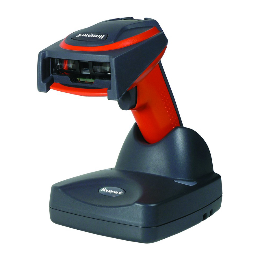
Page 20: Cordless System: Main Components
Cordless System: Main Components About the Battery Use only the Li-ion battery packs provided by Honeywell. Use of any battery not sold/manufactured by Honeywell may result in damage not covered by the warranty. Power is supplied to the cordless image scanner by a rechargeable battery that is integrated in the image scanner handle. -
Page 21: Proper Disposal Of The Battery
Replace it after the battery is unable to hold an adequate charge. • If you are not sure if the battery or charger is working properly, send it to Honeywell or an authorized Honeywell International Inc. service center for inspection. Refer to... -
Page 22: Base Charge Mode
Base Charge Mode In order for the battery to be charged, there must be enough voltage for the cir- cuitry to work. There are three conditions during which power can be supplied to the base: Condition 1:9VDC power supply connected to the barrel connector Condition 2:12VDC host power source only Condition 3:5VDC host power source only The chart below describes each selection by condition. -
Page 23: Linking Image Scanner To Base
Image Scanner Modes The 3820/3820i is capable of working in single image scanner mode, multiple image scanner mode, or with Bluetooth devices, other than the 2020 base. Unlinking the Image Scanner If the base has an image scanner linked to it, that image scanner must be unlinked before a new image scanner can be linked. -
Page 24: Single Image Scanner Operation
Single Image Scanner Operation There are two link modes to accommodate different applications: Locked Link Mode and Open Link Mode. Scan the appropriate barcodes included in the Open Link and Locked Link Mode explanations that follow to switch from one mode to another. -
Page 25: Multiple Image Scanner Operation
Multiple Image Scanner Operation To put the image scanner in multiple image scanner mode, scan the barcode below. Once you scan this barcode, the image scanner is unlinked from the base and must be placed into the base to re-link. Multiple Image Scanner Operation Note: Multiple Image Scanner Operation Mode allows you to link up to 7 image scanners to one base. -
Page 26: Changing Image Scanner Name - Via Barcodes
83), where name is the new image scanner name. Scan the Reset bar- code (page 1-8 or on the manual). You may use Barcode Builder, which is included with Quick*View. You may download Quick*View from the Honeywell International Inc. website: www.honeywell.com/aidc 1 - 8... -
Page 27: Image Scanner Report
Image Scanner Report Scan the barcode below to generate a report for the connected image scanners. The report indicates the port, work group, image scanner name, and address. Image Scanner Report Application Work Groups Your cordless system can have up to seven image scanners linked to one base. You can also have up to seven work groups. -
Page 28: Application Work Group Selection
Application Work Group Selection This programming selection allows you to assign an image scanner to a work group by scanning the barcode below. You may then program the settings (e.g., beeper volume, prefix/suffix, data formatter) that your application requires. * Group 0 Group 2 Group 4 Group 6... -
Page 29: Resetting The Standard Product Default Settings: Current Application Work Group
Resetting the Standard Product Default Settings: Current Application Work Group If you aren’t sure what programming options are in your image scanner, or you’ve changed some options and want the standard product default settings restored, scan the Standard Product Default Settings: Current Application Group barcode below. -
Page 30: Using The Image Scanner With Bluetooth Devices
Using the Image Scanner with Bluetooth Devices The 3820/3820i image scanner may be used either with the 2020 base or with other Bluetooth devices. Scanning the Non-Base Bluetooth Connection bar- code below allows the image scanner to be used with other Bluetooth devices (e.g., PDA, PC - Bluetooth USB Adapter). -
Page 31: Alarm Sound Type
and then set the time-out duration (from 0-3000 seconds) by scanning digits on Programming Chart sec (no alarm). Base Alarm Duration Note: If you are out of range when you scan a barcode, you will receive an error beep even if you do not have the alarm set. You receive the error beep since the data could not be communicated to the base or the host. -
Page 32: Batch Mode Transmit Delay
Batch Mode Transmit Delay Sometimes when accumulated scans are sent to the host system, the transmis- sion of those scans is too fast for the application to process. To program a transmit delay between accumulated scans, scan one of the following delays. Note: In most cases, a short (250 ms (milliseconds) delay is ideal;... -
Page 33: 3820/3820I Led Sequences And Their Meaning
Menu Operation Green Flash Red, blinking 2020 LED Sequences and Their Meaning The base contains a red LED that indicates the status of the unit and verifies its communication with the host system and a green LED that indicates image scanner battery charge condition. -
Page 34: Basic Operation Of The Cordless System
Receiving Data (2020 only) Blink LED for short duration in multiple pulses. Base requests status from its own Bluetooth radio Note: Charging only occurs with external power applied to the 2020 or 12 volt Host power. Charge Condition Image Scanner inserted into base >80% charged... -
Page 35: System Conditions
RF (Radio Frequency) Module Operation The cordless system uses a state-of-the-art two-way Bluetooth radio to transmit and receive data between the image scanner and the base. Designed for point- to-point and multipoint-to-single point applications, the radio operates using a license free ISM band, which sends relatively small data packets at a fast data rate over a radio signal with randomly changing frequencies, makes the cord- less system highly responsive to a wide variety of data collection applications and resistant to noisy RF environments. -
Page 36: Communication Between The Cordless System And The Host
Out of Range and Back into Range with Data Accumulation Mode The image scanner may store a number of symbols (approximately 500 UPC symbols, others may vary) when out of range and then send them to the base when back in range. You will not hear a communication error beep in this mode, but you will hear a short buzz when you pull the trigger if the radio communica- tion is not working. - Page 37 2. Disconnect the keyboard cable from the back of the terminal/computer. 3. Connect the appropriate interface cable to the base and to the terminal/ computer and keyboard. Make sure the cables are secured in the wireways in the bottom of the base and that the base sits flat on a...
-
Page 38: Reading Techniques
Reading Techniques The image scanner has a view finder that projects a bright red aiming beam that corresponds to its horizontal field of view. The aiming line should be centered horizontally over the barcode; it will not read if the aiming line is in any other direction. -
Page 39: Plug And Play
Plug and Play Plug and Play barcodes provide instant image scanner set up for commonly used interfaces. Note: After you scan one of the codes, power cycle the host terminal to have the interface in effect. Keyboard Wedge Connection If you want your system programmed for an IBM PC AT and compatibles key- board wedge interface with a USA keyboard, scan the barcode below. -
Page 40: Wand Emulation Plug & Play
Wand Emulation Plug & Play In Wand Emulation mode, the image scanner decodes the barcode then sends data in the same format as a wand scanner. The Code 39 Format converts all symbologies to Code 39. The Same Code Format transmits UPC, EAN, Code 128 and Interleaved 2 of 5 without any changes, but converts all other symbologies to Code 39. -
Page 41: Connecting The Base With Usb
Each barcode above also programs the following suffixes for each symbology: Symbology EAN 8 EAN 13 UPC A UPC E Code 39 Interleaved 2 of 5 Code 128 * Code 128 ** * Suffixes programmed for Code 128 with IBM 4683 Port 5B, IBM 4683 Port 9B HHBCR- 1, and IBM 4683 Port 17 Interfaces **Suffixes programmed for Code 128 with IBM 4683 Port 9 HHBCR-2 Interface Connecting the Base with USB... -
Page 42: Ibm Surepos
For additional USB programming and technical information, refer to Honeywell “USB Application Note,” available at Note: Without using the 9-volt external, power supply, the base only uses enough power from the host to operate the interface. The image scanner’s battery is not charged when in this mode. Using the 9-volt, external power supply allows the image scanner’s battery to be charged,... -
Page 43: Usb Hid
USB Com Port Emulation Scan the following code to program the 3820/3820i to emulate a regular RS- 232-based Com Port. If you are using a Microsoft® Windows® PC, you will need to download a driver from the Honeywell website (www.honeywell.com/ aidc . -
Page 44: Connecting The Base With Serial Wedge
ACK/NAK On Connecting the Base with Serial Wedge The 2020 uses TTL signal levels to wedge into an RS-232 serial network. Use only 2020 serial wedge cables to prevent damage to the base. Refer to necting the Base with RS-232 Serial Port communications protocol. - Page 45 5. Plug the other serial connector into the other device connection and tighten the two screws. 6. Plug the power supply barrel connector to the base, and plug the power supply into the AC source. 7. Once the base has been fully connected, power up the computer. To set up the serial wedge terminal ID, use the serial terminal ID 050 and follow the instructions on page...
- Page 46 1 - 28...
-
Page 47: Chapter 2 - Terminal Interfaces
(before scanning Save), scan the Discard code on the Programming Chart, scan the Terminal ID barcode, scan the digits, and the Save code again. Note: The default interface for the 2020-5BE is Keyboard Wedge (Term ID = 003). Terminal ID Save Note: After scanning one of these codes, you must power cycle your computer. -
Page 48: Supported Terminals
Supported Terminals Terminal Esprit Heath Zenith IBM 102 key IBM 122 key IBM 122 key IBM 122 key IBM 122 key IBM DOS/V 106 key IBM SurePOS IBM SurePOS IBM Thinkpad IBM Thinkpad IBM Thinkpad I/O 122 key Lee Data Olivetti Olivetti RS-232 TTL... - Page 49 Wand Emulation (Code 39 Format) Wand Emulation (Same Code Format) * Default for 2020-5BE. **It is best to use the Plug and Play barcodes, beginning on interfaces, rather than scanning the terminal ID listed in this table. Model(s) 078, 078A, 79, 80, 191, 196,...
-
Page 50: Keyboard Country
Keyboard Country Scan the appropriate country code below to program the keyboard for your country. As a general rule, the following characters are supported, but need special care for countries other than the United States: @ | $ # { } [ ] = / ‘ \ < > ~ * United States Brazil Czech Republic... - Page 51 Keyboard Country (continued) Italy Latin America Netherlands (Dutch) Norway Poland Portugal Romania Russia Slovakia Spain Sweden Switzerland (German) Turkey F Turkey Q U.K. 2 - 5...
-
Page 52: Keyboard Style
Please refer to the Honeywell website (www.honeywell.com/aidc) for complete keyboard country support information and applicable interfaces. If you need to program a keyboard for a country other than one listed above, scan the Pro- gram Keyboard Country barcode below, then scan the numeric barcode(s) for the appropriate country from the inside back cover, then the Save barcode. -
Page 53: Keyboard Modifiers
Emulate External Keyboard should be scanned if you do not have an external keyboard (IBM AT or equivalent). Emulate External Keyboard Note: After scanning the Emulate External Keyboard barcode, you must power cycle your computer. Keyboard Modifiers This modifies special keyboard features, such as CTRL+ ASCII codes and Turbo Mode. -
Page 54: Connecting The Base With Rs-232 Serial Port
Automatic Direct Connect Mode: This selection can be used if you have an IBM AT style terminal and the system is dropping characters. Default = Off Automatic Direct Connect Mode On Connecting the Base with RS-232 Serial Port 1. Turn off power to the terminal/computer. 2. -
Page 55: Rs-232 Baud Rate
5. Once the base has been fully connected, power up the computer. All communication parameters between the image scanner and terminal must match for correct data transfer through the serial port using RS-232 protocol. Scanning the RS-232 interface barcode, programs the image scanner for an RS-232 interface at 115,200 baud, parity–none, 8 data bits, 1 stop bit, and adds a suffix of a CR LF. -
Page 56: Rs-232 Word Length: Data Bits, Stop Bits, And Parity
RS-232 Word Length: Data Bits, Stop Bits, and Parity Data Bits sets the word length at 7 or 8 bits of data per character. If an applica- tion requires only ASCII Hex characters 0 through 7F decimal (text, digits, and punctuation), select 7 data bits. -
Page 57: Host Ack Selection
transmission, the host sends the XON character (DC1, hex 11). Data transmis- sion continues where it left off when XOFF was sent. Default = RTS/CTS, XON/ XOFF and ACK/NAK Off. RTS/CTS On XON/XOFF On ACK/NAK On Host ACK Selection Some applications require that the host terminal (or server) approve or reject incoming barcode data and notify the operator of these actions. -
Page 58: Host Ack Enable
Commands may be strung together to create custom response sequences. An example of a command string is listed below. 0<ESC>4<ESC>5<ESC>6, The above example will make an image scanner in application work group zero beep low, medium, high. Once Host ACK is enabled, the system works as follows: •... - Page 59 2020 Host Escape Commands Command Action <ESC> a Indicate as if successful menu change made <ESC> b Indicate as if unsuccessful menu change made <ESC> 1 Illuminate green LED for 135 milliseconds (followed by at least 70 mSecs. dark time when multiple blinks) <ESC>...
-
Page 60: Wand Emulation
Wand Emulation Wand Emulation Connection The Wand Emulation Connection barcodes should be used if you want to change the terminal ID only , without changing any other image scanner set- tings. We recommend using Wand Emulation Plug & Play barcodes to program your image scanner to emulate a wand reader. -
Page 61: Wand Emulation Transmission Rate
Wand Emulation Transmission Rate The transmission rate is limited by the terminal’s ability to receive data without dropping characters. Default = 25 inches/second. Wand Emulation Polarity The Polarity can be sent as standard with black bars high, or reversed with white bars high. -
Page 62: Wand Emulation Data Block Size
Wand Emulation Data Block Size This transmits the data in smaller blocks to prevent buffer overflow. Default = 40 . * 40 Wand Emulation Delay Between Blocks This sets the delay time between data blocks. Default = 50ms. * 50ms 150ms 500ms Wand Emulation Overall Checksum... -
Page 63: Chapter 3 - Output
Output Image Scanner Functions Good Read Indicators Beeper – Good Read The beeper may be programmed On or Off in response to a good read. Turning this option off, only turns off the beeper response to a good read indication. All error and menu beeps are still audible. -
Page 64: Beeper Pitch - Good Read
Beeper Pitch – Good Read The beeper pitch codes modify the pitch (frequency) of the beep the image scanner emits on a good read. Default = Medium. Low (1600 Hz) * Medium (3250 Hz) High (4200 Hz) Beeper Duration – Good Read The beeper duration codes modify the length of the beep the image scanner emits on a good read. -
Page 65: Good Read Delay
Good Read Delay This sets the minimum amount of time before the image scanner can read another barcode. Default = 0 ms (No Delay. ) * No Delay Short Delay (500 ms) Medium Delay (1000 ms) Long Delay (1500 ms) User-Specified Good Read Delay If you want to set your own length for the good read delay, scan the barcode below, then set the delay (from 0-30,000 milliseconds) by scanning digits from... - Page 66 Read Time-Out (Serial Trigger Mode) Use this selection to set a time-out (in milliseconds) of the image scanner’s trigger when using serial commands to trigger the image scanner. Once the image scanner has timed out, you can activate the image scanner either by pressing the trigger or using a serial trigger command.
-
Page 67: Automatic Trigger
“image scanner power time-out timer” is reset. If the image scanner is placed in the 2020 cradle and the battery is in the process of being charged, the image scanner will not go into power down mode. -
Page 68: Hands Free Time-Out
Hands Free Time-Out The Automatic Trigger and Presentation Modes are referred to as “hands free” modes. If the image scanner’s trigger is pulled when using a hands free mode, the image scanner changes to manual trigger mode. You can set the time the image scanner should remain in manual trigger mode by setting the Hands Free Time-Out. -
Page 69: Centering Window
Centering Window Use the centering feature to narrow the image scanner’s field of view so the image scanner reads only the barcode you want. When centering is turned on, the image scanner only reads codes that intersect or are contained within the centering window you set up. -
Page 70: Preferred Symbology
Example: If you have two barcodes next to one another and the centering window is set to 40% left edge and 60% right edge, only the barcode that intersects that window will be decoded. Preferred Symbology The 3820/3820i can be programmed to specify one symbology as a higher priority over other symbologies in situations where both bar code symbologies appear on the same label, but the lower priority symbology cannot be disabled. -
Page 71: Symbology Chart
High Priority Symbology To specify the high priority symbology, scan the High Priority Symbology bar code below. On the Symbology Chart on page A-1, find the symbology you want to set as high priority. Locate the Hex value for that symbology and scan the 2 digit hex value from the Programming Chart (inside back cover). -
Page 72: Output Sequence Overview
Output Sequence Overview Require Output Sequence When turned off, the barcode data will be output to the host as the image scanner decodes it. When turned on, all output data must conform to an edited sequence or the image scanner will not transmit the output data to the host device. -
Page 73: Output Sequence Editor
5. End Output Sequence Editor Scan F F to enter an Output Sequence for an additional symbology, or Save to save your entries. Other Programming Selections • Discard This exits without saving any Output Sequence changes. Output Sequence Editor Enter Sequence Require Output Sequence When an output sequence is Required , all output data must conform to an edited sequence or the image scanner will not transmit the output data to the host... - Page 74 Output Sequence Example In this example, you are scanning Code 93, Code 128, and Code 39 barcodes, but you want the image scanner to output Code 39 1st, Code 128 2nd, and Code 93 3rd, as shown below. Note: Code 93 must be enabled to use this example. You would set up the sequence editor with the following command line: SEQBLK62999941FF6A999942FF69999943FF The breakdown of the command line is shown below:...
-
Page 75: Multiple Symbols
To program the previous example using specific lengths, you would have to count any programmed prefixes, suffixes, or formatted characters as part of the length. If you use the example on page 3-12, but assume a <CR> suffix and specific code lengths, you would use the following command line: SEQBLK62001241FF6A001342FF69001243FF The breakdown of the command line is shown below: SEQBLK sequence editor start command... -
Page 76: No Read
No Read With No Read turned On , the image scanner sends an “NR” to the host if you pull and release the trigger without reading a code (e.g., bad barcode). If No Read is turned Off , the “NR” will not be sent to the host. No Read On If you want a different notation than “NR,”... -
Page 77: Chapter 4 - Data Editing
Data Editing Prefix/Suffix Overview When a barcode is scanned, additional information is sent to the host computer along with the barcode data. This group of barcode data and additional, user-defined data is called a “message string.” The selections in this section are used to build the user-defined data into the message string. -
Page 78: To Clear One Or All Prefixes Or Suffixes
Step 4. Determine the hex value from the 1252) on page A-2, for the prefix or suffix you wish to enter. Step 5. Scan the 2 digit hex value from the cover of this manual. Step 6. Repeat Steps 4 and 5 for every prefix or suffix character. Step 7. -
Page 79: To Add A Carriage Return Suffix To All Symbologies
Step 3. Scan the 2 digit hex value from the Programming Chart inside the back cover of this manual or scan 9, 9 for all symbologies. Your change is automatically saved. To Add a Carriage Return Suffix to All Symbologies Scan the following barcode if you wish to add a carriage return suffix to all sym- bologies at once. -
Page 80: Suffix Selections
Suffix Selections Add Suffix Clear One Suffix Clear All Suffixes Function Code Transmit When this selection is enabled and function codes are contained within the scanned data, the image scanner transmits the function code to the terminal. Charts of these function codes are provided in Supported Interface Keys start- ing on... -
Page 81: Intercharacter Delay
Intercharacter Delay An intercharacter delay of up to 495 milliseconds may be placed between the transmission of each character of scanned data. Scan the Intercharacter Delay barcode below, then scan the number of milliseconds and the SAVE bar- code using the Programming Chart To remove this delay, scan the Intercharacter Delay barcode, then set the num- ber of steps to 0. -
Page 82: Interfunction Delay
Interfunction Delay An interfunction delay of up to 495 milliseconds may be placed between the transmission of each segment of the message string. Scan the Interfunction Delay barcode below, then scan the number of milliseconds and the SAVE bar- code using the Programming Chart To remove this delay, scan the Interfunction Delay barcode, then set the num- ber of steps to 0. -
Page 83: Chapter 5 - Data Formatting
Data Formatting Data Format Editor Introduction You may use the Data Format Editor to change the image scanner’s output. For example, you can use the Data Format Editor to insert characters at certain points in barcode data as it is scanned. The selections in the following pages are used only if you wish to alter the output. -
Page 84: Other Programming Selections
Step 4. Code I.D. In the Appendix data format. Locate the Hex value for that symbology and scan the 2 digit hex value from the this manual. Step 5. Length Specify what length (up to 9999 characters) of data will be acceptable for this symbology. - Page 85 ASCII Conversion Chart (Code Page 1252) numeric value (00-99) for the number of times it should be sent.) E9 Send all but the last “nn” characters, starting from the current cursor posi- tion. Syntax = E9nn (nn is the numeric value (00-99) for the number of characters that will not be sent at the end of the message.) Move Commands F5 Move the cursor ahead “nn”...
-
Page 86: Data Format Editor
ters to be replaced and xx through zz and zz E5 Terminates character replacement. Syntax = E5. FE Compare character in current cursor position to the character “xx.” If char- acters are equal, increment cursor. If characters are not equal, no format match. -
Page 87: Alternate Data Formats
When Data Formatter is required, all input data must conform to an edited for- mat or the image scanner does not transmit the input data to the host device. Data Format On, Format Required Alternate Data Formats Alternate formats allow you “single shot” capability to scan one barcode using a different data format than your primary format. - Page 88 5 - 6...
-
Page 89: Introduction
Symbologies Introduction This programming section contains the following menu selections. Refer to Chapter 10 for settings and defaults. • All Symbologies • China Post Code • Codabar • Codablock F • Code 11 • Code 16K • Code 39 • Code 32 Pharmaceutical (PARAF) •... -
Page 90: Message Length
Message Length You are able to set the valid reading length of some of the barcode symbologies. If the data length of the scanned barcode doesn’t match the valid reading length, the image scanner will issue an error beep. You may wish to set the same value for minimum and maximum length to force the image scanner to read fixed length barcode data. -
Page 91: Codabar
Codabar <Default All Codabar Settings> Codabar * On Codabar Start/Stop Characters Start/Stop characters identify the leading and trailing ends of the barcode. You may either transmit, or not transmit Start/Stop characters. Default = Don’t Transmit . Transmit * Don’t Transmit Codabar Check Character Codabar check characters are created using different “modulos.”... -
Page 92: Codabar Concatenation
When Check Character is set to Validate, but Don’t Transmit , the unit will only read Codabar barcodes printed with a check character, but will not transmit the check character with the scanned data. * No Check Character Validate Modulo 16, but Don’t Transmit Validate Modulo 16 and Transmit Codabar Concatenation... -
Page 93: Codabar Message Length
Codabar Message Length Scan the barcodes below to change the message length. Refer to Message Length on page 6-2 for additional information. Minimum and Maximum lengths = 2-60. Minimum Default = 4, Maximum Default = 60. Minimum Message Length Maximum Message Length Code 39 <... -
Page 94: Code 39 Check Character
Code 39, continued Code 39 Check Character No Check Character indicates that the image scanner reads and transmits barcode data with or without a check character. When Check Character is set to Validate, but Don’t Transmit, the unit only reads Code 39 barcodes printed with a check character, but will not transmit the check character with the scanned data. -
Page 95: Code 39 Append
Code 39, continued Code 39 Append This function allows the image scanner to append the data from several Code 39 barcodes together before transmitting them to the host computer. When this function is enabled, the image scanner stores those Code 39 barcodes that start with a space (excluding the start and stop symbols), and does not immedi- ately transmit the data. -
Page 96: Full Ascii
Full ASCII If Full ASCII Code 39 decoding is enabled, certain character pairs within the barcode symbol will be interpreted as a single character. For example: $V will be decoded as the ASCII character SYN, and /C will be decoded as the ASCII character #. -
Page 97: Code 39 Code Page
Code 39 Code Page Code pages define the mapping of character codes to characters. If the data received does not display with the proper characters, it may be because the bar- code being scanned was created using a code page that is different from the one the host program is expecting. -
Page 98: Interleaved 2 Of 5 Message Length
When Check Digit is set to Validate and Transmit, the image scanner only reads Interleaved 2 of 5 barcodes printed with a check digit, and will transmit this digit at the end of the scanned data. Default = No Check Digit. * No Check Digit Validate, but Don’t Transmit Validate and Transmit... -
Page 99: Code 93
Code 93 < Default All Code 93 Settings > Code 93 * On Code 93 Message Length Scan the barcodes below to change the message length. Refer to Message Length on page 6-2 for additional information. Minimum and Maximum lengths = 0-80. Minimum Default = 0, Maximum Default = 80. Minimum Message Length Maximum Message Length Code 93 Code Page... -
Page 100: Straight 2 Of 5 Industrial
Straight 2 of 5 Industrial (three-bar start/stop) <Default All Straight 2 of 5 Settings> Straight 2 of 5 Industrial * Off Straight 2 of 5 Industrial Message Length Scan the barcodes below to change the message length. Refer to Message Length on page 6-2 for additional information. -
Page 101: Straight 2 Of 5 Iata Message Length
Straight 2 of 5 IATA, continued * Off Straight 2 of 5 IATA Message Length Scan the barcodes below to change the message length. Refer to Message Length on page 6-2 for additional information. Minimum and Maximum lengths = 1-48. Minimum Default = 4, Maximum Default = 48. Minimum Message Length Maximum Message Length Matrix 2 of 5... -
Page 102: Matrix 2 Of 5 Message Length
Matrix 2 of 5 Message Length Scan the barcodes below to change the message length. Refer to Message Length on page 6-2 for additional information. Minimum and Maximum lengths = 1-80. Minimum Default = 4, Maximum Default = 80. Minimum Message Length Maximum Message Length Code 11 <Default All Code 11 Settings>... -
Page 103: Code 11 Message Length
Code 11, continued Code 11 Message Length Scan the barcodes below to change the message length. Refer to Message Length on page 6-2 for additional information. Minimum and Maximum lengths = 1-80. Minimum Default = 4, Maximum Default = 80. Minimum Message Length Maximum Message Length Code 128... -
Page 104: Isbt 128 Concatenation
Code 128, continued ISBT 128 Concatenation In 1994 the International Society of Blood Transfusion (ISBT) ratified a standard for communicating critical blood information in a uniform manner. The use of ISBT formats requires a paid license. The ISBT 128 Application Specification describes 1) the critical data elements for labeling blood products, 2) the current recommendation to use Code 128 due to its high degree of security and its space-efficient design, 3) a variation of Code 128 that supports concatenation... -
Page 105: Code 128 Function Code Transmit
Code 128 Function Code Transmit By default, Code 128 function codes are not transmitted with Code 128 barcode data. However, if you wish to transmit Code 128 function codes with the bar- code data, scan the Function Codes On barcode, below. * Function Codes Off Function Codes On Telepen... -
Page 106: Telepen Message Length
Telepen Message Length Scan the barcodes below to change the message length. Refer to Message Length on page 6-2 for additional information. Minimum and Maximum lengths = 1-60. Minimum Default = 1, Maximum Default = 60. Minimum Message Length Maximum Message Length UPC A <Default All UPC A Settings>... -
Page 107: Upc A Number System
UPC A Number System The numeric system digit of a U.P.C. symbol is normally transmitted at the beginning of the scanned data, but the unit can be programmed so it will not transmit it. Default = On. * On UPC A Addenda This selection adds 2 or 5 digits to the end of all scanned UPC A data. -
Page 108: Upc A Addenda Separator
UPC A Addenda Separator When this feature is on, there is a space between the data from the barcode and the data from the addenda. When turned off, there is no space. Default = On. * On UPC-A/EAN-13 with Extended Coupon Code Use the following codes to enable or disable UPC-A and EAN-13 with Extended Coupon Code. -
Page 109: Upc E0 And Upc E1
UPC E0 and UPC E1 Most U.P.C. barcodes lead with the 0 number system. For these codes, use the UPC E0 selection. If you need to read codes that lead with the 1 number sys- tem, use the UPC E1 selection. Default = On (UPC E0) and Off (UPC E1). * UPC E0 On UPC E0 Off UPC E1 On... -
Page 110: Upc E0 And Upc E1 Addenda Separator
UPC E0 and UPC E1 Addenda Separator When this feature is on, there is a space between the data from the barcode and the data from the addenda. When turned off, there is no space. Default = On. * On UPC E0 Check Digit Check Digit specifies whether the check digit should be transmitted at the end of the scanned data or not. -
Page 111: Upc E0 Addenda
UPC E0 Addenda This selection adds 2 or 5 digits to the end of all scanned UPC E data. Default = Off for both 2 Digit and 5 Digit Addenda. 2 Digit Addenda On 5 Digit Addenda On EAN/JAN 13 <Default All EAN/JAN Settings>... -
Page 112: Ean/Jan 13 Addenda
EAN/JAN 13 Addenda This selection adds 2 or 5 digits to the end of all scanned EAN/JAN 13 data. Default = Off for both 2 Digit and 5 Digit Addenda. 2 Digit Addenda On 5 Digit Addenda On EAN/JAN 13 Addenda Required When Addenda Required is set to on, the image scanner will only read EAN/ JAN 13 barcodes that have addenda. -
Page 113: Isbn Translate
ISBN Translate This selection causes EAN-13 Bookland symbols to be translated into their equivalent ISBN number format. Default = Off. * Off EAN/JAN 8 <Default All EAN/JAN 8 Settings> EAN/JAN 8 * On EAN/JAN 8 Check Digit This selection allows you to specify whether the check digit should be transmit- ted at the end of the scanned data or not. -
Page 114: Ean/Jan 8 Addenda
EAN/JAN 8 Addenda This selection adds 2 or 5 digits to the end of all scanned EAN/JAN 8 data. Default = Off for both 2 Digit and 5 Digit Addenda. 2 Digit Addenda On 5 Digit Addenda On EAN/JAN 8 Addenda Required When Addenda Required is set to on, the image scanner will only read EAN/ JAN 8 barcodes that have addenda. -
Page 115: Msi
<Default All MSI Settings> * Off MSI Check Character Different types of check characters are used with MSI barcodes. You can program the image scanner to read MSI barcodes with Type 10 check characters. Default = Validate Type 10, but Don’t Transmit. When Check Character is set to Validate and Transmit , the image scanner will only read MSI barcodes printed with the specified type check character, and will transmit this character at the end of the scanned data. -
Page 116: Plessey Code
Plessey Code <Default All Plessey Code Settings> Plessey Code * Off Plessey Message Length Scan the barcodes below to change the message length. Refer to Message Length on page 6-2 for additional information. Minimum and Maximum lengths = 4-48. Minimum Default = 4, Maximum Default = 48. Minimum Message Length Maximum Message Length GS1 DataBar Omnidirectional... -
Page 117: Gs1 Databar Limited
GS1 DataBar Omnidirectional * On GS1 DataBar Limited < Default All GS1 DataBar Limited Settings > GS1 DataBar Limited * On GS1 DataBar Expanded < Default All GS1 DataBar Expanded Settings > 6 - 29... -
Page 118: Gs1 Databar Expanded Message Length
GS1 DataBar Expanded * On GS1 DataBar Expanded Message Length Scan the barcodes below to change the message length. Refer to Message Length on page 6-2 for additional information. Minimum and Maximum lengths = 4-74. Minimum Default = 4, Maximum Default = 74. Minimum Message Length Maximum Message Length GS1 Emulation... -
Page 119: China Post Code
China Post Code <Default All China Post Code Settings> China Post Code * Off China Post Message Length Scan the barcodes below to change the message length. Refer to Message Length on page 6-2 for additional information. Minimum and Maximum lengths = 2-80. -
Page 120: Korea Post Code
Korea Post Code <Default All Korea Post Code Settings> Korea Post Code * Off Korea Post Message Length Scan the barcodes below to change the message length. Refer to Message Length on page 6-2 for additional information. Minimum and Maximum lengths = 2-80. -
Page 121: Posicode Message Length
You have to have PosiCode A and B on to read any of the PosiCode symbolo- gies. A and B On (No Limited) A and B and Limited A On (Limited B Off) * A and B and Limited B On (Limited A Off) PosiCode Message Length Scan the barcodes below to change the message length. -
Page 122: Codablock F
Codablock F <Default All Codablock F Settings> Codablock F * Off Codablock F Message Length Scan the barcodes below to change the message length. Refer to Message Length on page 6-2 for additional information. Minimum and Maximum lengths = 1-2048. Minimum Default = 1, Maximum Default = 2048. Minimum Message Length Maximum Message Length Code 16K... -
Page 123: Code 16K
Code 16K * Off Code 16K Message Length Scan the barcodes below to change the message length. Refer to Message Length on page 6-2 for additional information. Minimum and Maximum lengths = 0-160. Minimum Default = 1, Maximum Default = 160. Minimum Message Length Maximum Message Length Code 49... -
Page 124: Code 49 Message Length
Code 49 Message Length Scan the barcodes below to change the message length. Refer to Message Length on page 6-2 for additional information. Minimum and Maximum lengths = 1-81. Minimum Default = 1, Maximum Default = 81. Minimum Message Length Maximum Message Length 6 - 36... -
Page 125: Chapter 7 - Interface Keys
Interface Keys Keyboard Function Relationships The following Keyboard Function Code, Hex/ASCII Value, and Full ASCII “CTRL”+ relationships apply to all terminals that can be used with the image scanner. Refer to page 2-7 enable Control + ASCII mode. Function Code HEX/ASCII Value Full ASCII “CTRL”... - Page 126 The last five characters in the Full ASCII “CTRL”+ column ( [ \ ] 6 - ), apply to US only. The following chart indicates the equivalents of these five characters for different countries. Country United States Belgium Scandinavia France Germany Italy Switzerland...
- Page 127 Supported Interface Keys IBM AT/XT and PS/2 Compatibles, WYSE PC/AT ASCII Supported Keys Reserved Enter (KP) Cap Lock ALT make ALT break CTRL make CTRL break CR/Enter Reserved Reserved Delete CR/Enter Insert Escape Home Print Back Space Back Tab * IBM 3191/92, 3471/72, 3196/97, 3476/77, Telex (all models) IBM XTs and IBM, DDC, Memorex Compatibles...
- Page 128 Supported Interface Keys IBM, Memorex Telex (102)* ASCII Supported Keys Reserved Enter New Line Tab/Field Forward Delete Field Exit Insert Clear Error Reset Home Print Back Space Back Tab * IBM 3196/97, 3476/77, 3191/92, 3471/72, Memorex Telex (all models) with 102 key keyboards ** Memorex Telex with 88 key keyboards 7 - 4...
- Page 129 Supported Interface Keys Esprit 200, 400 ANSI ASCII Supported Keys Reserved New Line New Line New Line Escape Insert Back Space Back Tab Esprit 200, 400 Esprit 200, 400 ASCII Supported Keys Supported Keys Reserved Reserved New Line New Line New Line New Line Delete...
- Page 130 Supported Interface Keys Apple Mac/iMac ASCII Supported Keys Reserved Enter/Numpad Enter CAPS ALT make ALT break CNTRL make CNTRL break RETURN APPLE make APPLE break RETURN Ins Help Home Prnt Scrn BACKSPACE LSHIFT TAB BACKSPACE 7 - 6...
-
Page 131: Chapter 8 - Utilities
Utilities To Add a Test Code I.D. Prefix to All Symbologies This selection allows you to turn on transmission of a Code I.D. before the decoded symbology. (See the Symbology Chart, page A-1) for the single char- acter code that identifies each symbology.) This action first clears all current prefixes, then programs a Code I.D. -
Page 132: Image Scanner Report
Image Scanner Report Scan the barcode below to generate a report for the connected image scan- ners. The report indicates the port, work group, image scanner name, and address. To assign a name to your image scanner, refer to Syntax" on page 10-1. -
Page 133: Resetting The Standard Product Default Settings: All Application Work Groups
Resetting the Standard Product Default Settings: All Application Work Groups The following barcode defaults all of the work groups to the factory settings. Standard Product Default Settings: Menu Commands starting on page 10-6 list the standard product default settings for each of the commands (indicated by an asterisk (*) on the program- ming pages). - Page 134 8 - 4...
-
Page 135: Chapter 9 - Visual Xpress
Visual Xpress Visual Xpress Introduction Visual Xpress provides a wide range of PC-based programming functions that can be performed on an imager connected to your PC's COM port. Visual Xpress allows you to download upgrades to the imager's firmware, change pro- grammed parameters, and create and print programming barcodes. -
Page 136: Installing Visual Xpress From The Web
Note: Visual Xpress requires .NET software. If .NET is not installed on your PC, you will be prompted to install it during the Visual Xpress installation. 1. Access the Honeywell web site at 2. Click on Software Downloads. 3. Select your product from the dropdown list. -
Page 137: Chapter 10 - Serial Programming Commands
The serial programming commands can be used in place of the programming barcodes. Both the serial commands and the programming barcodes will pro- gram the 2020. For complete descriptions and examples of each serial pro- gramming command, refer to the corresponding programming barcode in this manual. -
Page 138: Query Commands
Data The new value for a menu setting, identified by the Tag and Sub- Tag. Storage A single character that specifies the storage table to which the command is applied. An exclamation point (!) performs the com- mand’s operation on the device’s volatile menu configuration table. A period (.) performs the command’s operation on the device’s non-volatile menu configuration table. -
Page 139: Responses
Responses The device responds to serial commands with one of three responses: ACKIndicates a good command which has been processed. ENQIndicates an invalid Tag or SubTag command. NAKIndicates the command was good, but the Data field entry was out of the allowable range for this Tag and SubTag combination, e.g., an entry for a mini- mum message length of 100 when the field will only accept 2 characters. -
Page 140: Trigger Commands
Example #4: What are the device’s settings for all Codabar selections? Enter: cbr?. Response: CBRENA1[ACK], SSX0[ACK], CK20[ACK], CCT1[ACK], MIN2[ACK], MAX60[ACK], DFT[ACK]. This response indicates that the device’s Codabar Coding Enable (CBRENA) is set to 1, or on; the Start/Stop Character (SSX) is set to 0, or Don’t Transmit; the Check Character (CK2) is set to 0, or Not Required;... -
Page 141: Resetting The Standard Product Default Settings: All Application Work Groups
Menu Commands starting on each of the commands (indicated by an asterisk (*) on the programming pages). Note: Scanning this barcode also causes both the image scanner and the base to perform a reset and become unlinked. Refer to Scanner to Base" Standard Product Default Settings: Note: If your image scanner is in multiple image scanner mode and you scan either the current or all application group default barcode, you will hear up... -
Page 142: Menu Commands
Menu Commands Selection Base Charge Mode Image Scanner Modes - Single Multiple Image Scan- Operation Image Scanner Name Image Scanner Report Application Work Group Selections Standard Product Defaults: Current Application Work Group Standard Product Defaults: All Applica- tion Work Groups Non-Base Bluetooth Connection Bluetooth PIN Code... -
Page 143: Terminal Interfaces
Selection Out-of-Range Alarm Alarm Sound Type Data Accumulation Mode Batch Mode Transmit Delay Factory Default Set- tings Terminal Interfaces Terminal ID Setting * Indicates default Base Alarm Duration (Range 1 - 3000 sec (*0)) Image Scanner Alarm Duration (Range 1 - 3000 sec (*0)) Base Alarm Type Image Scanner Alarm... - Page 144 Selection Program Keyboard Country 10 - 8 Setting * Indicates default *U.S.A. Belgium Brazil Canada (French) Czech Republic Denmark Finland (Sweden) France Germany/Austria Greece Hungary Israel (Hebrew) Italy Latin America Netherlands (Dutch) Norway Poland Portugal Romania Russia Slovakia Spain Sweden Switzerland (German) Turkey F Turkey Q...
- Page 145 Selection Keyboard Style Keyboard Modifiers Serial Port Connection Baud Rate Setting * Indicates default *Regular Caps Lock Shift Lock Automatic Caps Lock Emulate External Keyboard *Control + ASCII Off Control + ASCII On *Turbo Mode Off Turbo Mode On *Numeric Keypad Off Numeric Keypad On *Auto Direct Conn.
- Page 146 Selection Word Length: Data Bits, Stop Bits, and Parity RS-232 Handshaking Wand Emulation Con- nection Wand Emulation Transmission Rate 10 - 10 Setting * Indicates default 7 Data, 1 Stop, Parity Even 7 Data, 1 Stop, Parity None 7 Data, 1 Stop, Parity 7 Data, 2 Stop, Parity Even 7 Data, 2 Stop, Parity...
-
Page 147: Output Selections
Selection Wand Emulation Polar- Wand Emulation Idle Wand Emulation Data Block Size Wand Emulation Delay Between Blocks Wand Emulation Over- all Checksum Output Selections Beeper - Good Read Beeper Volume - Good Read Beeper Pitch - Good Read (Frequency) Beeper Duration - Good Read LED - Good Read Setting... - Page 148 Selection Number of Beeps - Good Read Good Read Delay User-Specified Good Read Delay Trigger Mode Reread Delay User-Specified Reread Delay 10 - 12 Setting * Indicates default Range 1 - 9 *No Delay Short Delay (500 ms) Medium Delay (1000 Long Delay (1500 ms) Range 0 - 30,000 ms *Manual Trigger...
-
Page 149: Prefix/Suffix Selections
Selection Centering Preferred Symbology Output Sequence Edi- Require Output Sequence Multiple Symbols No Read Video Reverse Prefix/Suffix Selections Add CR Suffix to All Symbologies Prefix Setting * Indicates default Centering On *Centering Off Left of Centering Win- dow *40 Right of Centering Win- dow *60 *Off High Priority Symbol-... -
Page 150: Data Formatter Selections
Selection Suffix Function Code Trans- Intercharacter Delay User Specified Inter- character Delay Interfunction Delay Intermessage Delay Data Formatter Selections Data Format Editor Data Formatter Alternate Data For- mats Symbologies All Symbologies Codabar Codabar 10 - 14 Setting * Indicates default Add Suffix Clear One Suffix Clear All Suffixes... - Page 151 Selection Codabar Start/Stop Char. Codabar Check Char. Codabar Concatena- tion Codabar Message Length Code 39 Code 39 Code 39 Start/Stop Char. Code 39 Check Char. Code 39 Message Length Code 39 Append Code 32 Pharmaceuti- cal (PARAF) Code 39 Full ASCII Interleaved 2 of 5 Setting * Indicates default...
- Page 152 Selection Interleaved 2 of 5 Interleaved 2 of 5 Check Digit Interleaved 2 of 5 Mes- sage Length Code 93 Code 93 Code 93 Message Length Straight 2 of 5 Indus- trial Straight 2 of 5 Indus- trial Straight 2 of 5 Indus- trial Message Length Straight 2 of 5 IATA Straight 2 of 5 IATA...
- Page 153 Selection Matrix 2 of 5 Message Length Code 11 Code 11 Code 11 Check Digits Required Code 11 Message Length Code 128 Code 128 ISBT Concatenation Code 128 Message Length Code 128 Code Page Code 128 Function Code Transmit ISBT Concatenation Telepen Telepen Telepen Output...
- Page 154 Selection UPC A UPC A UPC A Check Digit UPC A Number Sys- UPC A 2 Digit Addenda UPC A 5 Digit Addenda UPC A Addenda Required UPC A Addenda Separator UPC E UPC E0 UPC E1 UPC E Expand UPC E Check Digit UPC E Number Sys- UPC E 2 Digit...
- Page 155 Selection UPC E 5 Digit Addenda UPC E Addenda Required UPC E Addenda Separator EAN/JAN 13 EAN/JAN 13 EAN/JAN 13 Check Digit EAN/JAN 13 2 Digit Addenda EAN/JAN 13 5 Digit Addenda EAN/JAN 13 Addenda Required EAN/JAN 13 Addenda Separator ISBN Translate EAN/JAN 8 EAN/JAN 8...
- Page 156 Selection EAN/JAN 8 5 Digit Addenda EAN/JAN 8 Addenda Required EAN/JAN 8 Addenda Separator Coupon Code MSI Check Character MSI Message Length Plessey Code Plessey Code Plessey Message Length GS1 DataBar GS1 DataBar GS1 DataBar Limited GS1 DataBar Limited 10 - 20 Setting * Indicates default *Off...
- Page 157 Selection GS1 DataBar Expanded GS1 DataBar Expanded GS1 DataBar Expanded Msg. Length EAN•UCC Emulation China Post Code China Post Code China Post Code Msg. Length Korea Post Code Korea Post Code Korea Post Code Msg. Length PosiCode Setting * Indicates default Default All GS1 DataBar Expanded Settings...
-
Page 158: Minimizing Bluetooth/Ism Band Network Activity
Selection PosiCode PosiCode Msg. Length Trioptic Code Codablock F Codablock F Codablock F Msg. Length Code 16K Code 16K Code 16K Code 49 Code 49 Code 49 Minimizing Bluetooth/ISM Band Network Activity 10 - 22 Setting * Indicates default A and B On A and B and Limited A *A and B and Limited B Minimum (2 - 80) *4... - Page 159 Selection Auto Reconnect Mode Maximum Link Attempts Relink Time-Out Setting * Indicates default *0 (0 - 100) *3 (1 - 100) Serial Command Page # Indicates a numeric entry BT_ACM1 BT_ACM0 BT_MLA### BT_RLT### 10 - 23...
- Page 160 10 - 24...
-
Page 161: Chapter 11 - Product Specifications
Product Specifications 3820 Product Specifications Parameter Dimensions (Typical): Height Length Width Weight (with battery) Light Source Scan Rate Skew Angle Pitch Angle Horizontal Velocity Scan Contrast Battery: Lithium Ion Battery Capacity: Storage: Radio: Frequency Range Data Rate Temperature Ranges: Operating Battery Charge Storage Humidity... -
Page 162: 3820I Product Specifications
3820i Product Specifications Parameter Dimensions (Typical): Height Length Width Weight (with battery) Light Source Scan Rate Skew Angle Pitch Angle Horizontal Velocity Scan Contrast Battery: Lithium Ion Battery Capacity: Storage: Radio: Frequency Range Data Rate Temperature Ranges: Operating Battery Charge Storage Humidity Mechanical Drop... -
Page 163: 2020-5Be Product Specifications
2020-5BE Product Specifications Parameter Dimensions (Typical): Height Length Width Weight Voltage: DC Barrel Host Port Current Draw: 5 Volt Host 9 Volt DC Barrel 12 Volt Host Charge Rate to Scanner Battery 41° F to +104° F (5° C to +40° C) -
Page 164: 2020-Cbe Product Specifications
2020-CBE Product Specifications Parameter Dimensions (Typical): Height Length Width Weight Voltage: DC Barrel Current Draw: 9 Volt DC Barrel Charge Rate to Scanner Battery 41° F to +104° F (5° C to +40° C) 9 Volt DC Barrel (external power) - Page 165 Standard Cable Pinouts Keyboard Wedge 11 - 5...
- Page 166 Standard Cable Pinouts Wand Emulation 11 - 6...
- Page 167 Standard Cable Pinouts Serial Output 11 - 7...
- Page 168 Standard Cable Pinouts 11 - 8...
-
Page 169: Chapter 12 - Maintenance
Inspect the base’s interface cable and connector for wear or other signs of dam- age. A badly worn cable or damaged connector may interfere with image scan- ner operation. Contact your Honeywell distributor for information about cable replacement. Cable replacement instructions are on for further information. -
Page 170: Replacing The 2020 Interface Cable
Replacing the 2020 Interface Cable: 1. Turn the power to the host system OFF. 2. Disconnect the base’s cable from the terminal or computer. 3. Turn the base upside down. 4. Pull the connector out while maintaining pressure on the connector release clip. - Page 171 Troubleshooting the Image Scanner Note: Make sure that your image scanner’s battery is charged. Note: Please visit the Services and Support section of our website www.honeywell.com/aidc image scanner and the base. Is the image scanner having trouble reading your symbols? If the image scanner isn’t reading symbols well, check that the symbols:...
- Page 172 The image scanner won’t read your barcode at all. 1. Scan the sample barcodes in the back of this manual. If the image scanner reads the sample barcodes, check that your barcode is readable. Verify that your barcode symbology is enabled (see 2.
-
Page 173: Chapter 13 - Customer Support
Telephone - Hong Kong: +852-3188-3485 or 2511-3050 Telephone - China: +86 21 6361 3818 E-mail: aptechsupport@handheld.com Japan Telephone: +813 5770-6312 E-mail: aptechsupport@handheld.com Malaysia Telephone: +603-6201-7020 E-mail: aptechsupport@handheld.com Online Technical Assistance You can also access technical assistance online at www.honeywell.com/aidc. 13 - 1... -
Page 174: Product Service And Repair
Product Service and Repair Honeywell provides service for all its products through service centers throughout the world. To obtain warranty or non-warranty service, contact the appropriate location below to obtain a Return Material Authorization number (RMA #) before returning the product. -
Page 175: Limited Warranty
Honeywell or its authorized representatives. This warranty shall extend from the time of shipment for the duration published by Honeywell for the product at the time of purchase ("Warranty Period"). Any defective product must be returned (at purchaser’s expense) during the War- ranty Period to Honeywell’s factory or authorized service center for inspection. - Page 176 Honeywell extends these war- ranties only to users of the products. These warranties are non-transferable. The duration of the limited warranty for the 2020 and 3820/3820i is three (3) years. The duration of the limited warranty for the image scanner battery is one (1) year.
-
Page 177: Symbology Chart
Reference Charts Symbology Chart Code Symbology China Post Codabar Codablock F Code 11 Code 16K Code 39 Code 32 Pharma- ceutical (PARAF) Code 49 Code 93 Code 128 UCC/EAN-128 EAN/JAN-8 EAN/JAN-13 EAN-13 with Extended Coupon Code Interleaved 2 of 5 Note: “m”... -
Page 178: Ascii Conversion Chart (Code Page 1252
ASCII Conversion Chart (Code Page 1252 Note: This table applies to U.S. style keyboards. Certain characters may differ depending on your Country Code/PC regional settings. Char A - 2 Char “ & ‘ < > Char Char ‘... - Page 179 Dec. Char Dec. € € ‚ ƒ „ … † ‡ ˆ ‰ Š ‹ Œ Ž ‘ ’ “ ” • – — ˜ ™ š › œ ž Ÿ Char Dec. ¡ ¢ £ ¤ ¥ ¦ § ¨...
-
Page 180: Code Page Mapping Of Printed Barcodes
Code Page Mapping of Printed Barcodes Code pages define the mapping of character codes to characters. If the data received does not display with the proper characters, it may be because the barcode being scanned was created using a code page that is different from the one the host program is expecting. -
Page 181: Appendix B - Minimizing Bluetooth/Ism Band Network
Minimizing Bluetooth/ISM Band Network Activity The settings described below can help you customize the re-linking behavior of the cordless linear imaging system to obtain the best compromise between convenience and low interference. Note: ISM band refers to the 2.4 to 2.48 GHz frequency band used by wireless networks, cordless phones, and Bluetooth. -
Page 182: Maximum Link Attempts
Event Image scanner power down due to Power Time-Out Timer setting (see page 3-4) Image scanner reset due to firmware upgrade Image scanner reset due to battery change Image scanner placed in different base unit Maximum Link Attempts The Maximum Link Attempts setting controls the number of times the image scanner tries to form a connection with a base unit or PC. -
Page 183: Relink Time-Out
Relink Time-Out Relink Time-Out controls the idle time between re-link attempts. An attempt to link an image scanner to a base unit typically lasts up to 5 seconds. This is the time when the image scanner is actually attempting to contact base unit. Relink Time-Out controls the amount of time, in seconds, that elapses between the end of one connection attempt and the start of the next. - Page 184 Auto Reconnect Mode set to 1 Maximum Link Attempts set to 0 Relink Time-Out set to 10 Image Scanner Power Time-Out Timer set to 1800: Note: See Image Scanner Power Time-Out Timer on page 3-4. The image scanner attempts to connect to the base unit every 15 seconds, measured from start of attempt to start of attempt.
- Page 185 Sample Symbols UPC A 0 123456 7890 Interleaved 2 of 5 1234567890 Code 128 Code 128 EAN 13 9 780330 290951 EAN 8 3210 5 UPC-E 456123...
- Page 186 Sample Symbols Code 39 Codabar BC321 Code 93 A13579B Straight 2 of 5 Industrial 123456-9$ Matrix 2 of 5 123456 6543210 GS1 DataBar (01)00123456789012...
- Page 187 Programming Chart Note: If you make an error while scanning the letters or digits (before scanning Save), scan Discard, scan the correct letters or digits, and Save. Discard Save...
- Page 188 Honeywell 700 Visions Drive P.O. Box 208 Skaneateles Falls, NY 13153-0208 3820-UG Rev C 7/08...