
Related Manuals for AEG ARE i2 - HF


Summary of Contents for AEG ARE i2 - HF
- Page 1 Compact Reader ARE i2 - HF Installation Guide for Systems with a Serial Interface RS 232...
-
Page 2: Table Of Contents
Pin assignment of the SAB connectors ..................11 Mounting of the external antenna / of the AMP 4 / AMP 8 ..............13 VISUAL SIGNAL LAMPS .................... 14 AEG ID INSTRUCTION SET ..................15 General ..............................15 5.1.1 Entering instuctions ......................... 15 5.1.2... - Page 3 5.3.2 CID – suppression of ID Codes ......................22 5.3.3 CN – suppression of No Reads ......................23 5.3.4 INIT – initialization ......................... 24 5.3.5 MC – mirror code ..........................24 5.3.6 TOR – maximum reading time ......................24 5.3.7 SI –...
- Page 4 MD 0 - Continuous Reading ........................45 STARTUP AND TESTING THE READER ..............46 INSTRUCTIONS ......................47 FCC INFORMATION ....................48 HOTLINE ........................49 REVISIONS ......................50 --------------------------------------------------------------------------------4/50--------------------------------------------------------------------------------...
-
Page 5: Introduction
Introduction This document will describe the components of the Compact Reader System ARE i2 / RS 232 and the procedure how to do the first set up of the reader. The main features of the reader are listed below: integrated RS232 Interface with tunable baudrate ... -
Page 6: Grounding Of The Reader
It is recommended to protect the housing against heavy mechanical interactions and drippy fluids. Attention! The side of the housing showing the antenna symbol must not be brought next to a metal surface. This could lead to a significant change of the properties of the antenna circuit, which in turn reduces the reading range considerably. -
Page 7: Connecting Of The Power Supply Cable
Figure 1: Connecting of the plug Put on the sealing 2 to the SAB Cab (A). Plug in the SAB Cab to the connector at the bottom of the reader device (B). There is only one way to plug in the SAB Cab to the connector rim of the reader. Fasten the SAB Cab with the help of the screws. -
Page 8: Using The Switchboard Cable Id 70212
3.3.2 Using the switchboard cable ID 70212 Power supply: brown = + 9 .. 30 Volt white = ground Data interface: green = RXD (readers data input) yellow = TXD (readers data output) grey = ground 3.3.3 Using a self assembled connecting cable Using the following SAB cabs you can assemble your own connecting cable. -
Page 9: Assembling Of The Cable Pipe
Attention! The minimum voltage at the readers input mustn’t be lower then 9V. The maximum length of the serial RS232 cable is 15m. 3.3.3.1 Assembling of the cable pipe Breakthrough the prepared areas at the surface of the SAB Cabs. There are two prepared areas seen at the SAB Cab: central and at one side of the cab. - Page 10 Put all the removed parts (nut (5), cable fastener (3), pipe (4),) and the cable pipe of the SAB Cab as well (1 to 4) to the cable. Cable Figure 3: Mounting for the cable Remove the outer isolation of the cable at a length of 6cm . ...
-
Page 11: Pin Assignment Of The Sab Connectors
3.3.3.3 Pin assignment of the SAB connectors RS232 (9 Pins Sub-D female) shielding TxD (reader) GND (0V) RxD (reader) V+ (+24V) ARE I2 black green Figure 4: Pin assignment of the SAB connectors --------------------------------------------------------------------------------11/50--------------------------------------------------------------------------------... - Page 12 RS232 (9 Pins Sub-D female) shielding TxD (reader) GND (0V) RxD (reader) V+ (+24V) ARE I2 blue grey Figure 5: Pin assignment of the SAB connectors --------------------------------------------------------------------------------12/50--------------------------------------------------------------------------------...
-
Page 13: Mounting Of The External Antenna / Of The Amp 4 / Amp 8
Mounting of the external antenna / of the AMP 4 / AMP 8 If you have an i2 with external antenna the connector is on the topside of the reading device. You just have to plug the antenna into the connector and bold it on. Alternative you can connect an AMP 4 / AMP 8 with this connector, too. -
Page 14: Visual Signal Lamps
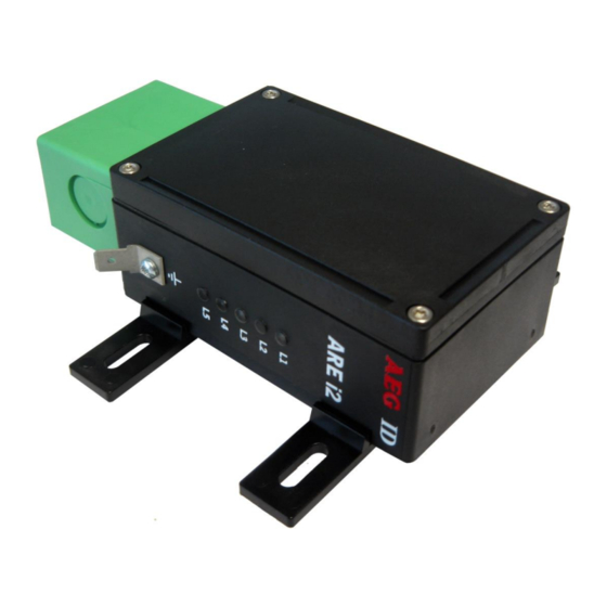
Visual signal lamps To show the operational state or results there are 5 LED at the side of the housing. A E G L1: twinkles, if the processor works. ARE i2 L2: twinkles one time after successful instruction L3: twinkles one time after bad instruction L4: lit, if the reader receives data’s at the serial data port (Rx) L5: lit, if the reader sends data’s at the serial data port (Tx) Figure 6: Visual signal lamps... -
Page 15: Aeg Id Instruction Set
All numbers (e.g. sectors, blocks) are in the hexadecimal format (see chapter 9). With the command CS you can change to the alternative instruction set. If the reader is set to alter- native instruction set, you can change back to the AEG ID instruction set via the command AEG (see chapter 5.3.3). -
Page 16: Output Format
5.1.2 Output format Generally, every input terminated by <CR> is acknowledged by the reader. The following response protocols are different: 5.1.2.1 Instruction specific output After entering a valid command without a parameter value, the system answers by sending the param- eter value and <CR>. -
Page 17: Incorrect Instruction / Error Codes
Command: <CR> Output: <CR> 5.1.4 Incorrect instruction / error codes If a command is not entered correctly, the reader sends one of the following error codes: ERROR CODE MEANING NAK #00 <CR> unknown command NAK #02 <CR> wrong parameter NAK #03 <CR> EEPROM error NAK #04 <CR>... -
Page 18: Upper And Lower Case
NAK #41 <CR> ISO 15693 error 02h: command not recognized NAK #42 <CR> ISO 15693 error 03h: option not supported NAK #43 <CR> ISO 15693 error 0Fh: unknown error (default) NAK #44 <CR> ISO 15693 error 10h: block does not exist NAK #45 <CR>... -
Page 19: Instructions For The Hardware Settings
Instructions for the hardware settings 5.2.1 BD – baudrate The command BD enables the change of the baud rate. The settings are directly effective. BD <SP> parameter <CR> Input format: 2 <CR> Output (example): Parameter: PARAMETER FUNCTION 4800 baud 9600 baud 19200 baud 38400 baud 57600 baud... -
Page 20: Rst - Reset
1 <CR> Output (example): Parameter: PARAMETER FUNCTION 5.2.4 RST – reset With the command RST the reader does a warmstart and loads the saved settings from the internal EEPROM. The antenna field is off after the reset. RST <CR> Input format: ACK <CR>... -
Page 21: We - Write Eeprom
FF <CR> Output (example): Parameter: PARAMETER 1 FUNCTION 0005h..079Fh address PARAMETER 2 FUNCTION 00h..FFh data 5.2.6 VER – version With the command VER the reader sends the actual firmware version. VER <CR> Input format: AEG ID V1.22 <CR> Output (example): --------------------------------------------------------------------------------21/50--------------------------------------------------------------------------------... -
Page 22: Instructions For Reading Settings
Instructions for reading settings 5.3.1 CE – convert error code With CE=1 the reader sends no error codes, except the no read error, during the md0 mode or the commands Get Tag. The leds are not influenced by this command. This command has only effect in the ISO 14443A standard. -
Page 23: Cn - Suppression Of No Reads
Example: A, B, C are different transponder codes, N is NoRead error code: Sequence of reading cycles Output sequence Output sequence after filtering with after filtering with CN=0 und CID=1 CN=1 und CID=1 N, N, ..,N, A, A, A, ..A, N,N, N, N, ..,N, A, N, .. -
Page 24: Init - Initialization
PARAMETER FUNCTION No suppression Suppression of equal transponder numbers 5.3.4 INIT – initialization With the command INIT all paramters of this command set are set to the default values. After that you can save the settings with the command VSAVE. INIT <CR>... -
Page 25: Set Iso Standard
5.3.7 SI – set iso standard With this command you can switch the iso standard of the reader. SI <SP> parameter <CR> Input format: 0 <CR> Output (example): Parameter: PARAMETER FUNCTION ISO 14443A ISO 15693 5.3.8 VSAVE – variables save With the command VSAVE the following parameters are saved to the internal EEPROM: , KM , KT... - Page 26 Note: The function VS shows just the settings that are used in the actual ISO standard. just available in the ISO 14443A standard just available in the ISO 15693 standard --------------------------------------------------------------------------------26/50--------------------------------------------------------------------------------...
-
Page 27: General Reading Instructions
General reading instructions 5.4.1 GA – get active The command GA causes one reading cycle. There are different cycles for different transpondertypes. This command is only available in the ISO 14443A standard. Mifare standard 1K/4K: request (REQA) anticollision select Mifare Ultralight/Desfire request (REQA) anticollision level 1 select 1... -
Page 28: Hd - Halt Detected Code
anticollision level 2 select 2 ISO 15693: inventory The reader answers the UID of a transponder. The length of the UID can be between 4 and 8 bytes. GT <CR> Input format: 625E562A <CR> Output (example): 5.4.3 HD – halt detected code The command HD mutes the last selected transponder. -
Page 29: Rdm - Read
RD <SP> parameter 2 <CR> Input format ISO 15693 one block: RD <SP> parameter 2 <SP> parameter 3 <CR> Input format ISO 15693 multiple blocks: parameter 4 <CR> Output: Parameters: PARAMETER 1 FUNCTION 1 or 2 characters sector PARAMETER 2 FUNCTION 1 or 2 characters block/start block... -
Page 30: Wd - Write Page
Parameters: PARAMETER 1 FUNCTION 1 or 2 characters sector PARAMETER 2 FUNCTION 1 or 2 characters block/start block PARAMETER 3 FUNCTION 1 or 2 characters end block PARAMETER 4 FUNCTION 32 characters data (mifare 1K/4K) 8 characters data (ultralight) up to 64 charac- data (ISO 15693) ters 5.4.7 WD –... -
Page 31: Wdm - Write
PARAMETER 2 FUNCTION 1 or 2 character block PARAMETER 3 FUNCTION 32 characters mifare 1K/4K 8 characters ultralight up to 32 charac- ISO 15693 ters Note: The ISO 15693 regulates just the maximum length of one block. With the write instruction you can write multiple blocks at once. - Page 32 PARAMETER 3 FUNCTION 32 characters mifare 1K/4K 8 characters ultralight up to 32 charac- ISO 15693 ters Note: The ISO 15693 regulates just the maximum length of one block. With the write instruction you can write multiple blocks at once. The datalenght has to be at least the block size or a multiple of the block size.
-
Page 33: Mifare Instructions
Mifare instructions 5.5.1 AC – anticollision The command AC answers with the UID of the transponder, that will be selected with the next select command. For ultralight and DESFire transponders it is the anticollision level 1 command. AC <CR> Input format: 595B1B80 <CR>... -
Page 34: Log - Transponder Log In
PARAMETER FUNCTION key type A key type B 5.5.5 LOG – transponder log in The command LOG is only valid with mifare standard 1K/4K transponders. The log in is necessary to read or write a page: LOG <SP> parameter 1 <SP> parameter 2 <SP> parameter 3 <CR> Input format: LOG <SP>... -
Page 35: Pdc - Purse Decrement
PARAMETER 2 FUNCTION 1 character source block PARAMETER 3 FUNCTION 1 character target block PARAMETER 4 FUNCTION 8 characters new purse value PARAMETER 5 FUNCTION 2 character optional address 5.5.7 PDC – purse decrement With this command you can decrement a value. This command is only valid with mifare standard 1K/4K. You have to log in first. -
Page 36: Pic - Purse Increment
PARAMETER 4 FUNCTION 8 characters new purse value PARAMETER 5 FUNCTION 2 character optional address 5.5.8 PIC – purse increment With this command you can increment a value. This command is only valid with mifare standard 1K/4K. You have to log in first. PDC <SP>... -
Page 37: Piv - Purse Init Value
5.5.9 PIV – purse init value With this command you can initialize a value. This command is only valid with mifare standard 1K/4K. You have to log in first. PIV <SP> parameter 1 <SP> parameter 2 <SP> parameter 3 <SP> param- Input format: eter 4 <CR>... -
Page 38: Rq - Request
PARAMETER 2 FUNCTION 1 character block PARAMETER 3 FUNCTION 8 characters value PARAMETER 4 FUNCTION 2 characters optional address 5.5.11 RQ – request The RQ command answers the type of the detected transponder. RQ <SP> parameter <CR> Input format: ACK <CR> Output (example): Parameters: PARAMETER... -
Page 39: Wk - Write Key
ACK <CR> Output (example): 5.5.14 WK – write key With the command WK you save a key to the EEPROM. You can save 8 different keys. It is not possible to read out the saved keys. WK <SP> parameter 1 <SP> parameter 2 <CR> Input: ACK <CR>... -
Page 40: Iso 15693 Instructions
ISO 15693 instructions 5.6.1 AFI – application family identifier With this command you can change the application family identifier of the reader. The reader reads only transponders, with the same application family identifier as the reader. If the application family identifi- er is set to 00h the reader reads each transponder. -
Page 41: Gs - Get System Information
GMS <SP> parameter 1 <CR> Input format one block: GMS <SP> parameter 1 <SP> parameter 2 <CR> Input format multiple blocks: parameter 3 <CR> Output (example): Parameter: PARAMETER 1 FUNCTION 1 or 2 characters block/start block number PARAMETER 2 FUNCTION 1 or 2 characters end block number PARAMETER 3... -
Page 42: Lds - Lock Dsfid
ACK <CR> Output (example): Parameter: PARAMETER FUNCTION 0h..FFh block number 5.6.7 LDS – lock DSFID This command locks the DSFID of a transponder. You have to do a get tag first. LDS <CR> Input format: ACK <CR> Output (example): 5.6.8 MDR – my-d read This command reads one page of an Infineon my-d transponder. -
Page 43: Rtr - Reset To Ready
PARAMETER 2 FUNCTION 16 characters data 5.6.10 RTR – reset to ready With this command the transponder enteres the ready state. A muted transponder answers again after this command. RTR <CR> Input format: ACK <CR> Output (example): 5.6.11 WA – write AFI With this command the reader writes the AFI into the transponder. -
Page 44: Operating Modes Of The Reader
Operating Modes of the Reader There are two operational modes defined: MD 0 - continuous mode MD 2 - the reading process is triggered by the serial interface In the next capters can you find a detailed functional description. The default mode is MD 0. -
Page 45: Md 0 - Continuous Reading
exciter processor reading cycle reading cycle reading cycle interface NoRead reading process Figure 8: Software triggered reading operation with TOR>0 Please note: The TOR parameter is only active, if the GT-Command is applied. Within the time span defined by the value of TOR no NoRead will be output on the interface! MD 0 - Continuous Reading When operating continuously the exciter is switched on permanently. -
Page 46: Startup And Testing The Reader
XOFF/XON). Send the command „VER <CR>“ to the reader. The reader answers with the actual firmware version (e.g. AEG ID V1.23). Send the command “MD <SP> 0 <CR>” to the reader. The reader sends No Read messages (e.g. „FFFFFFFFFF“ or „XXXXXXXXXX“), while there is no transponder in the antenna field available. -
Page 47: Instructions
Instructions To avoid any reduction of the reading distance of the reader, the antenna must not be brought next to a metal surface. This could lead to a significant change of the properties of the antenna circuit, which in turn reduces the reading range considerably! To get reliable readings, the distance between antenna and transponder must be within the specified reading volume. -
Page 48: Fcc Information
FCC Information Federal Communications Commissions (FCC) Statement 15.21 You are cautioned that changes or modifications not expressly approved by the part responsible for com- pliance could void the user’s authority to operate the equipment. 15.105(b) This equipment has been tested and found to comply with the limits for a Class B digital device, pursuant to part 15 of the FCC rules. -
Page 49: Hotline
Hotline If there are questions or suggestions please call the hotline: Sales und Marketing: +49 (0)731-140088-0 Fax: +49 (0)731-140088-9000 e-mail: sales@aegid.de http:// www.aegid.de --------------------------------------------------------------------------------49/50--------------------------------------------------------------------------------... -
Page 50: Revisions
Revisions 22.07.11 Revision 00: Initial edition (FW) 28.07.11 Revision 01: Changes for reader with external antenna 19.08.11 Revision 02: AMP errorcode added 17.12.12 Revision 03: Command BS block size added Command BD baudrate added 18.05.16 Revision 04: FCC Information 13.12.16 Revision 05: pin assignment ARE 016 28.08.18...