Table of Contents
Advertisement
9201-B San Mateo Blvd N.E.
Albuquerque, New Mexico 87113
U.S.A.
CAGE: 6PC31
Telephone: 855-250-7027 (Toll-Free U.S.A./Canada)
Telephone: 602-365-7027 (International Direct)
Web site: www.bendixking.com/support
Installation Manual
KT 74 Mode S/ADS-B Out Transponder
Part Number
CAGE
89000007-000001
6PC31
Legal Notice
Export Control
This document contains technical data and is subject to U.S. export regulations. These commodities, technology, or
software were exported from the United States in accordance with the export administration regulations. Diversion
contrary to U.S. law is prohibited.
ECCN: 7E994.
Page T-1
Initial 15 Nov 2013
Publication Number D201308000037, Revision 0
© Honeywell International Inc. Do not copy without express permission of Honeywell.
Advertisement
Table of Contents

Related Manuals for Honeywell BendixKing KT 74


Summary of Contents for Honeywell BendixKing KT 74
- Page 1 United States in accordance with the export administration regulations. Diversion contrary to U.S. law is prohibited. ECCN: 7E994. Page T-1 Initial 15 Nov 2013 Publication Number D201308000037, Revision 0 © Honeywell International Inc. Do not copy without express permission of Honeywell.
- Page 2 Licensed Facility retains no copies of the Materials and you provide prior written notice to Honeywell. 2. Rights In Materials - Honeywell retains all rights in these Materials and in any copies thereof that are not expressly granted to you, including all rights in patents, copyrights, trademarks, and trade secrets. No license to use any Honeywell trademarks or patents is granted under this License Agreement.
- Page 3 9. Controlling Law - This License shall be governed and construed in accordance with the laws of the State of New York without regard to the conflicts of laws provisions thereof. This license sets forth the entire agreement between you and Honeywell and may only be modified by a writing duly executed by the duly authorized representatives of the parties.
- Page 4 INSTALLATION MANUAL 89000007 Blank Page Page T-4 15 Nov 2013 © Honeywell International Inc. Do not copy without express permission of Honeywell.
- Page 5 KT 74 Mode S/ADS-B Out Transponder Revision History Table TI-2 shows the revision history of this IM. Table TI-2. Revision History Revision Number Revision Date 15 Nov 2013 Page TI-1 15 Nov 2013 © Honeywell International Inc. Do not copy without express permission of Honeywell.
- Page 6 INSTALLATION MANUAL 89000007 Blank Page Page TI-2 15 Nov 2013 © Honeywell International Inc. Do not copy without express permission of Honeywell.
- Page 7 NOTE: Refer to the Revision History in the TRANSMITTAL INFORMATION section for revision data. Revision Revision Date Put in Revision Revision Date Put in Number Date Manual Number Date Manual Page RR-1 15 Nov 2013 © Honeywell International Inc. Do not copy without express permission of Honeywell.
- Page 8 INSTALLATION MANUAL 89000007 Blank Page Page RR-2 15 Nov 2013 © Honeywell International Inc. Do not copy without express permission of Honeywell.
- Page 9 TR, a TR number will not be issued, or a TR has been deleted. Date Date Temporary Removed Revision Page Issue from Number Status Number Date Manual Manual Page RTR-1 15 Nov 2013 © Honeywell International Inc. Do not copy without express permission of Honeywell.
- Page 10 INSTALLATION MANUAL 89000007 Blank Page Page RTR-2 15 Nov 2013 © Honeywell International Inc. Do not copy without express permission of Honeywell.
- Page 11 15 Nov 2013 2-10 15 Nov 2013 indicates pages changed or added data F indicates a right foldout LF indicates a left foldout Page LEP-1 15 Nov 2013 © Honeywell International Inc. Do not copy without express permission of Honeywell.
- Page 12 15 Nov 2013 Calibration, and Checkout 15 Nov 2013 indicates pages changed or added data F indicates a right foldout LF indicates a left foldout Page LEP-2 15 Nov 2013 © Honeywell International Inc. Do not copy without express permission of Honeywell.
-
Page 13: Table Of Contents
Installation Kit ..........................1-5 1.10 Documentation Kit ........................1-5 1.11 Required Items ..........................1-5 1.12 Normal Operations Overview ...................... 1-6 1.13 Display ............................1-6 Page TC-1 15 Nov 2013 © Honeywell International Inc. Do not copy without express permission of Honeywell. -
Page 14: Title Page
2.6.5 Squat Switch Input ........................2-11 2.6.6 Ident Switch Input ........................2-11 2.6.7 External Standby Input ......................2-11 2.6.8 Audio Output ..........................2-11 Page TC-2 15 Nov 2013 © Honeywell International Inc. Do not copy without express permission of Honeywell. - Page 15 ADS-B Receiver Options ......................4-6 4.3.17 Audio Volume ..........................4-6 4.3.18 LCD Dim Point ..........................4-6 4.3.19 LCD Brightness Curve ......................... 4-6 Test items ............................ 4-6 Page TC-3 15 Nov 2013 © Honeywell International Inc. Do not copy without express permission of Honeywell.
- Page 16 SECTION 5 INSTRUCTIONS FOR CONTINUED AIRWORTHINESS .......... 5-1 Continued Airworthiness ......................5-1 Cleaning the KT 74 Transponder ....................5-1 APPENDIX A ENVIROMENTAL QUALIFICATION ................ A-1 Page TC-4 15 Nov 2013 © Honeywell International Inc. Do not copy without express permission of Honeywell.
- Page 17 Figure 2-11. Tray / BNC Connector Assembly ................2-19 Figure 3-1. KT 74 Basic Interconnect Diagram ................3-3 Figure 4-1. KT 74 Transponder ....................... 4-2 Page TC-5 15 Nov 2013 © Honeywell International Inc. Do not copy without express permission of Honeywell.
- Page 18 Table 2-3. Maximum Usable Cable Lengths ................. 2-14 Table 4-1. Warning Messages ......................4-7 Table 4-2. Fault Messages ......................4-8 Table A-1. Environmental Qualification Form ................. A-1 Page TC-6 15 Nov 2013 © Honeywell International Inc. Do not copy without express permission of Honeywell.
-
Page 19: Introduction
The signal names followed by an “*” show an active low signal. The symbols in Figure INTRO 1 show ESDS and moisture sensitive devices. Figure INTRO 1. Symbols Page INTRO-1 15 Nov 2013 © Honeywell International Inc. Do not copy without express permission of Honeywell. -
Page 20: Units Of Measure
Website: www.bendixking.com/support Email: techsupport@bendixking.com. 3. References A. Honeywell/Vendor Publications Related Honeywell publications in this manual are shown in the list that follows: Pub. No. D201308000036, KT 74 Mode S Transponder Pilot’s Guide ATA No. 20-00-03 (Pub. No. A09-1100-004), Standard Repair Procedures for Honeywell Avionics Equipment Instruction Manual. -
Page 21: Other Publications
RTCA DO 260B, Minimum Operational Performance Standards for 1090 MHz Extended Squitter Automatic Dependent Surveillance - Broadcast (ADS-B) and Traffic Information Services - Broadcast (TIS-B) (available at http://www.rtca.org/). Page INTRO-3 15 Nov 2013 © Honeywell International Inc. Do not copy without express permission of Honeywell. -
Page 22: Acronyms And Abbreviations
Code of Federal Regulations COMM communication decibel decibel milliwatt direct current diameter DIM. dimension distance measuring equipment enter ESDS electrostatic discharge sensitive Page INTRO-4 15 Nov 2013 © Honeywell International Inc. Do not copy without express permission of Honeywell. - Page 23 NACp navigational accuracy category for position NACv navigational accuracy category for velocity navigation integrity category NMEA National Marine Electronics Association number Page INTRO-5 15 Nov 2013 © Honeywell International Inc. Do not copy without express permission of Honeywell.
-
Page 24: Software History
At the publication date of this manual the software version identifier for the KT 74 is 3.9 and the FPGA version identifier is 110613a. The software and FPGA versions are subject to change without notice. Page INTRO-6 15 Nov 2013 © Honeywell International Inc. Do not copy without express permission of Honeywell. -
Page 25: Section 1 General Information
Connection to an external RS232 altitude encoder. Using serial altitude data allows the transponder to report altitude with 25 foot (7.62 m) resolution. Page 1-1 15 Nov 2013 © Honeywell International Inc. Do not copy without express permission of Honeywell. -
Page 26: Regulatory
Applicable documents EUROCAE ED-73E, EUROCAE ED-14G (RTCA DO- 160G), RTCA DO-181E, RTCA DO-260B Corrigenda 1 Software ED-12B (RTCA DO-178B) Level B DO-254B Class C Page 1-2 15 Nov 2013 © Honeywell International Inc. Do not copy without express permission of Honeywell. -
Page 27: Approved Deviations
Refer to Table 1-3 for the physical specifications. Table 1-3. Physical Specifications Characteristics Specification Inches (mm) Height 1.7 (42) Width 6.30 (160) Length 10.7 (272) Weight 2.8 pounds (1.35 Kg) Page 1-3 15 Nov 2013 © Honeywell International Inc. Do not copy without express permission of Honeywell. -
Page 28: Installation Approval
Your KT 74 Mode S transponder includes the following items. Refer to Table 1-4. Table 1-4. Included Transponder Items Unit Description BendixKing PN KT 74 Mode S transponder 89000007-000001 Mounting tray 89000007-041001 Page 1-4 15 Nov 2013 © Honeywell International Inc. Do not copy without express permission of Honeywell. -
Page 29: Installation Kit
Altitude encoder. You require an encoding altimeter or a blind encoder with either Gillham code or RS232 serial output. For best results, and simpler installation, an encoder with a serial output is recommended. Page 1-5 15 Nov 2013 © Honeywell International Inc. Do not copy without express permission of Honeywell. -
Page 30: Normal Operations Overview
The pressure altitude is displayed as a Flight Level, which is the pressure altitude in hundreds of feet. When non-standard atmospheric conditions apply, this may not match the altimeter indicated altitude. Page 1-6 15 Nov 2013 © Honeywell International Inc. Do not copy without express permission of Honeywell. -
Page 31: Mode Selector Knob
A new squawk code is set when the fourth digit is entered. If the code entry is not completed within 7 seconds, the changes are ignored and the previous code restored. Page 1-7 15 Nov 2013 © Honeywell International Inc. Do not copy without express permission of Honeywell. -
Page 32: Flight Timer
Pressing ENT toggles the altitude monitor at the current altitude. When altitude monitoring is in use, a small deviation pointer appears adjacent to the altitude display on the transponder. Page 1-8 15 Nov 2013 © Honeywell International Inc. Do not copy without express permission of Honeywell. -
Page 33: Ads-B Monitor
The heating element will take several minutes to raise the temperature around the display after initial power on. Page 1-9 15 Nov 2013 © Honeywell International Inc. Do not copy without express permission of Honeywell. -
Page 34: Limited Warranty
(2) Product alteration, modification or repair by anyone other than Seller or those specifically authorized by Seller; (3) accident, contamination, foreign object damage, abuse, neglect or negligence after Product shipment to Page 1-10 15 Nov 2013 © Honeywell International Inc. Do not copy without express permission of Honeywell. -
Page 35: Ads-B Compliance
Seller for use in Seller-manufactured Products; (6) products not manufactured by Honeywell (but manufacturer’s warranty is passed through to Buyer to the extent permitted); or (7) Products normally consumed in operation or which have a normal life inherently shorter than the foregoing warranty period including, but not limited to, consumables (e.g. - Page 36 Geometric vertical speed Squawk code Emergency status Quality indicator (NACp, NACv and GVA) Quality indicator (SIL and SDA) Version indicator Surface length/width Surface antenna offset Page 1-12 15 Nov 2013 © Honeywell International Inc. Do not copy without express permission of Honeywell.
-
Page 37: Faa 91.227 Compliance
The KT 74 can report ADS-B surface and airborne messages. The ADC, airspeed, or squat switch inputs can be utilized to determine air/ground status as explained in Section 2. Page 1-13 15 Nov 2013 © Honeywell International Inc. Do not copy without express permission of Honeywell. - Page 38 INSTALLATION MANUAL 89000007 Blank Page Page 1-14 15 Nov 2013 © Honeywell International Inc. Do not copy without express permission of Honeywell.
-
Page 39: Section 2 Installation
Lock the KT 74 transponder into the mounting tray using a 3/32 inch allen key, taking care not to over tighten the locking screw. 2.3 Installation Drawings Refer to Figure 2-1 for the Installation Drawing. Page 2-1 15 Nov 2013 © Honeywell International Inc. Do not copy without express permission of Honeywell. - Page 40 INSTALLATION MANUAL 89000007 Blank Page Page 2-2 15 Nov 2013 © Honeywell International Inc. Do not copy without express permission of Honeywell.
-
Page 41: Figure 2-1. Kt 74 Installation Drawing
INSTALLATION MANUAL 89000007 Figure 2-1. KT 74 Installation Drawing Page 2-3/2-4 15 Nov 2013 © Honeywell International Inc. Do not copy without express permission of Honeywell. -
Page 42: Cooling Requirements
2.5.1 Primary Interface – Pinout Refer to Table 2-1 and Figure 2-2 for the primary interface pinout locations. Page 2-5 15 Nov 2013 © Honeywell International Inc. Do not copy without express permission of Honeywell. -
Page 43: Table 2-1. Primary Interface Pinout Locations
NOTE: 1. These signals are different to the KT76A/KT78A pinout; on the KT76A and KT78A these signals are not usually connected in the aircraft. Page 2-6 15 Nov 2013 © Honeywell International Inc. Do not copy without express permission of Honeywell. -
Page 44: Secondary Interface - Pinout
Serial Alt out Output Serial Alt in Input Reserved Input Audio mute in Input Altitude alert Output Ground Audio + Output Audio - Output Reserved Page 2-7 15 Nov 2013 © Honeywell International Inc. Do not copy without express permission of Honeywell. -
Page 45: Orientation Diagram
DME with simple suppression output, a GPS with serial position output, and a simple lamp for the altitude alerter. This example is representative of a simple fixed gear 14-volt aircraft. Page 2-8 15 Nov 2013 © Honeywell International Inc. Do not copy without express permission of Honeywell. -
Page 46: Interface Details
If no lighting bus input is detected, the KT 74 will automatically control the front panel lighting based on the ambient light sensor. Page 2-9 15 Nov 2013 © Honeywell International Inc. Do not copy without express permission of Honeywell. -
Page 47: Mutual Suppression
The airspeed information can be used to provide an automatic air/ground determination for an ADS-B installation. Page 2-10 15 Nov 2013 © Honeywell International Inc. Do not copy without express permission of Honeywell. -
Page 48: Squat Switch Input
The audio output carries the traffic alert messages for TIS-A, and the altitude audio annunciator used by the altitude monitor function. Page 2-11 15 Nov 2013 © Honeywell International Inc. Do not copy without express permission of Honeywell. -
Page 49: Altitude Alerter Output
NOTE: TIS-A is a Mode S uplink service that is provided by some US approach radars. TIS-A coverage is limited to the coverage areas of those radars. There is no TIS-A provision outside the U.S.A. Page 2-12 15 Nov 2013 © Honeywell International Inc. Do not copy without express permission of Honeywell. -
Page 50: Molex Crimp Terminals
Avoid mounting the antenna within 3 feet (91.4 cm) of the ADF sense antenna or any COMM antenna and 6 feet (182.9 cm) from the transponder to the DME antenna. Page 2-13 15 Nov 2013 © Honeywell International Inc. Do not copy without express permission of Honeywell. -
Page 51: Antenna Cable
Cable Length in Length in dB/meter at MIL-C-17 Specialists Feet-Inches Meters 1,090 MHz Cables Type 2.54 0.59 M17/128 (RG400) 10-4 3.16 0.47 3C142B Page 2-14 15 Nov 2013 © Honeywell International Inc. Do not copy without express permission of Honeywell. -
Page 52: Bnc Connector
Secure the cable so that it cannot interfere with other systems. 2.8.2 BNC Connector This section describes the technique for attaching the antenna cable to the supplied blind-mate BNC connector. Page 2-15 15 Nov 2013 © Honeywell International Inc. Do not copy without express permission of Honeywell. -
Page 53: Figure 2-6. Coax Cable Stripping Dimensions
Refer to Figure 2-7. Figure 2-7. Coax Cable Inner and Outer Shield Orientation Page 2-16 15 Nov 2013 © Honeywell International Inc. Do not copy without express permission of Honeywell. -
Page 54: Figure 2-8. Coax Cable Outer Shield To Bnc Solder Location
7. Complete the assembly by installing the bushing over the center contact, and fitting the cap. Solder the cap in place in at least two places. Refer to Figure 2-10. Page 2-17 15 Nov 2013 © Honeywell International Inc. Do not copy without express permission of Honeywell. -
Page 55: Tray/Bnc Connector Assembly
The two Molex connectors should be passed through the openings in the rear of the tray, and then mounted firmly to the tray from the inside using the four M3 screws supplied. Refer to Figure 2-11. Page 2-18 15 Nov 2013 © Honeywell International Inc. Do not copy without express permission of Honeywell. -
Page 56: Figure 2-11. Tray / Bnc Connector Assembly
INSTALLATION MANUAL 89000007 Figure 2-11. Tray / BNC Connector Assembly Page 2-19 15 Nov 2013 © Honeywell International Inc. Do not copy without express permission of Honeywell. - Page 57 INSTALLATION MANUAL 89000007 Blank Page Page 2-20 15 Nov 2013 © Honeywell International Inc. Do not copy without express permission of Honeywell.
-
Page 58: Section 3 System Interconnect
INSTALLATION MANUAL 89000007 SECTION 3 SYSTEM INTERCONNECT 3.1 Basic Interconnect Diagram Refer to Figure 3-1 for the basic interconnect diagram. Page 3-1 15 Nov 2013 © Honeywell International Inc. Do not copy without express permission of Honeywell. - Page 59 INSTALLATION MANUAL 89000007 Blank Page Page 3-2 15 Nov 2013 © Honeywell International Inc. Do not copy without express permission of Honeywell.
-
Page 60: Figure 3-1. Kt 74 Basic Interconnect Diagram
INSTALLATION MANUAL 89000007 Figure 3-1. KT 74 Basic Interconnect Diagram Page 3-3/3-4 15 Nov 2013 © Honeywell International Inc. Do not copy without express permission of Honeywell. -
Page 61: Section 4 Post-Installation Configuration, Calibration, And Checkout
FUNC button while switching on the transponder and the setup system will run. Page 4-1 15 Nov 2013 © Honeywell International Inc. Do not copy without express permission of Honeywell. -
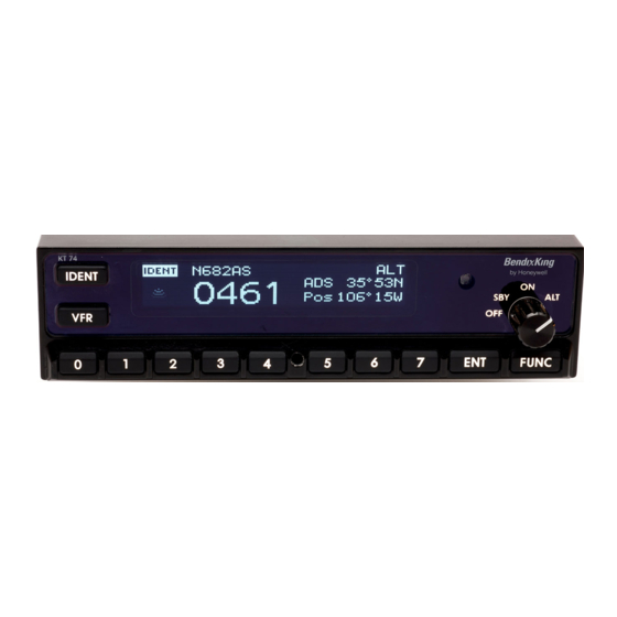
Page 62: Figure 4-1. Kt 74 Transponder
Pressing the FUNC button also accepts the selection and moves directly to the next screen. Refer to Figure 4-1. Figure 4-1. KT 74 Transponder Page 4-2 15 Nov 2013 © Honeywell International Inc. Do not copy without express permission of Honeywell. -
Page 63: Configuration Items
(6 and 7), select the range that corresponds to the aircraft. Press FUNC to accept and move to the next menu item. Page 4-3 15 Nov 2013 © Honeywell International Inc. Do not copy without express permission of Honeywell. -
Page 64: Aircraft Category
19,200 bps. BendixKing GPS receivers run at 9,600 bps for legacy systems, such as the KLN94, and 115200 for the high performance receiver in the KSN 765/770. Page 4-4 15 Nov 2013 © Honeywell International Inc. Do not copy without express permission of Honeywell. -
Page 65: Gps System Certification Level
GPS antenna is on the top of the tail, the GPS position could be 15 feet (4.6 m) or more from the nose of the aircraft. Page 4-5 15 Nov 2013 © Honeywell International Inc. Do not copy without express permission of Honeywell. -
Page 66: Ads-B Receiver Options
The interface check screen displays the current state of the external IDENT, external STANDBY and external GROUND inputs. Exercise these inputs to confirm the correct behavior. Page 4-6 15 Nov 2013 © Honeywell International Inc. Do not copy without express permission of Honeywell. -
Page 67: Altitude Check
180 seconds from system start-up 2 seconds once a GPS position data has been received by the transponder. Page 4-7 15 Nov 2013 © Honeywell International Inc. Do not copy without express permission of Honeywell. -
Page 68: Table 4-2. Fault Messages
Call BendixKing Customer Support BendixKing Customer Support: • Telephone: 855-250-7027 (Toll Free U.S.A./Canada) • Telephone: 602-365-7027 (International) • Website: www.bendixking.com/support • Email: techsupport@bendixking.com. Page 4-8 15 Nov 2013 © Honeywell International Inc. Do not copy without express permission of Honeywell. -
Page 69: Section 5 Instructions For Continued Airworthiness
The glass fascia covering the LCD screen should be lightly cleaned with a lint free cloth taking care not to scratch the surface. Page 5-1 15 Nov 2013 © Honeywell International Inc. Do not copy without express permission of Honeywell. - Page 70 INSTALLATION MANUAL 89000007 Blank Page Page 5-2 15 Nov 2013 © Honeywell International Inc. Do not copy without express permission of Honeywell.
-
Page 71: Appendix Aenviromental Qualification
8,000 to 55,000 feet (2.44 to 16.76 Km) in 15 seconds Overpressure 4.6.3 -15000 feet (-4.57 Km) Temperature variation Equipment tested to Category C Page A-1 15 Nov 2013 © Honeywell International Inc. Do not copy without express permission of Honeywell. - Page 72 Equipment tested to Category B Audio frequency 18.0 Equipment tested to Category B conducted susceptibility Induced signal 19.0 Equipment tested to Category AC susceptibility Page A-2 15 Nov 2013 © Honeywell International Inc. Do not copy without express permission of Honeywell.
- Page 73 Equipment identified as Category X, no test required Electrostatic discharge 25.0 Equipment tested to Category A Flammability 26.0 Manufacturer’s data sheets used to ensure Category C Page A-3 15 Nov 2013 © Honeywell International Inc. Do not copy without express permission of Honeywell.
- Page 74 INSTALLATION MANUAL 89000007 Blank Page Page A-4 15 Nov 2013 © Honeywell International Inc. Do not copy without express permission of Honeywell.