
Related Manuals for Makita LS0716FL


Summary of Contents for Makita LS0716FL
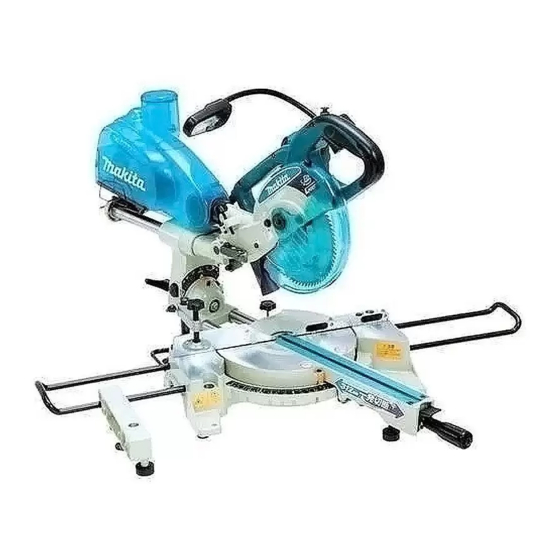
- Page 1 Slide Compound Saw MODEL LS0716FL 006944 DOUBLE INSULATION I N S T R U C T I O N M A N U A L WARNING: For your personal safety, READ and UNDERSTAND before using. SAVE THESE INSTRUCTIONS FOR FUTURE REFERENCE.
-
Page 2: Specifications
SPECIFICATIONS Model ................................LS0716FL Blade diameter..............................190 mm Hole (arbor) diameter............................20 mm Max. Miter angle ..........................Left 47° , Right 57° Max. Bevel angle..........................Left 45°, Right 45° Max. Cutting capacities (H x W) with blade 190 mm in diameter. Bevel angle Miter angle 45°... -
Page 3: Safety Instructions
2002/96/EC on waste electric and Intended use electronic equipment and its imple- The tool is intended for accurate straight and miter cut- mentation in accordance with ting in wood. With appropriate saw blades, aluminum national law, electric equipment that can also be sawed. have reached the end of their life must be collected separately and Power supply... -
Page 4: Additional Safety Rules For Tool
17. Avoid unintentional starting. damaged should be properly repaired or replaced Do not carry a plugged-in tool with a finger on the by an authorized service center unless otherwise switch. Ensure switch is off when plugging in. indicated in this instruction manual. Have defective 18. - Page 5 28. Connect miter saws to a dust collecting device Your risk from these exposures varies, depend- when sawing. ing on how often you do this type of work. To reduce your exposure to these chemicals: work 29. Select saw blades in relation to the material to in a well ventilated area and work with approved be cut.
-
Page 6: Installation
INSTALLATION Bench mounting When the tool is shipped, the handle is locked in the lowered position by the 006945 stopper pin. Release the stopper pin by lowering the handle slightly and pulling the stopper pin. 1. Stopper pin This tool should be bolted with two bolts to a level and stable surface using the 006946 bolt holes provided in the tool’s base. - Page 7 Positioning kerf board 006951 006952 1. Clamp screws 2. Kerf board 1. Saw blade 2. Kerf board 3. Left bevel cut 4. Straight cut 5. Right bevel cut This tool is provided with the kerf boards in the turn base to minimize tearing on the exit side of a cut.
- Page 8 Maintaining maximum cutting capacity 003927 This tool is factory adjusted to provide the maximum cutting capacity for a 190 mm saw blade. When installing a new blade, always check the lower limit position of the blade and if necessary, adjust it as follows: First, unplug the tool.
- Page 9 Guide fence has scale of every 10 mm increments. This acts as guide for cut- 006955 off piece. Adjusting the miter angle 006956 Loosen the grip by turning counterclockwise. Turn the turn base while pressing down the lock lever. When you have moved the grip to the position where the pointer points to the desired angle on the miter scale, securely tighten the grip clockwise.
- Page 10 Setting the fine-adjusting range of bevel angle 006959 Make sure that the entire part of window display on the scale label is green. If it not so, the fine-adjusting range of bevel angle becomes small. Loosen the lever, turn the fine adjusting screw until the entire part of the win- dow display becomes green.
- Page 11 When the green part in the window on the scale label is located on the right side, Turn the fine-adjusting screw counterclockwise and the green part 006963 moves to the left. Turn it until the entire part of the window display becomes green.
- Page 12 Turn the adjusting screw counterclockwise for fine adjustment so that the 006966 tool moves in such a direction as the motor unit becomes upright. 1. Adjusting screw 006967 1. Motor unit After fine-adjusting, tighten the lever firmly. 006968 Eg. When setting for left 30° bevel angle cutting Loosen the lever.
- Page 13 Push the handle to the right to tilt the saw blade until the pointer roughly 006970 points to an angle near the desired angle on the bevel scale. Then tighten the clamping screw clockwise. 1. Clamping screw Turn the adjusting screw clockwise for fine adjustment so that the tool 006971 moves in such a direction as the motor unit becomes upright.
-
Page 14: Switch Action
NEVER use the tool if it runs when you simply pull the switch trigger without pressing the lock-off button. Return tool to a Makita service center for proper repairs BEFORE further usage. • NEVER tape down or defeat purpose and function of lock-off button. - Page 15 Laser beam action 006976 CAUTION: • Never look into the laser beam. Direct laser beam may injure your eyes. To turn on the laser beam, press the upper position (I) of the switch. Press the lower position (O) to turn off. 1.
- Page 16 Always be sure that the tool is switched off and unplugged before installing or removing the blade. • Use only the Makita socket wrench provided to install or remove the blade. Failure to do so may result in overtightening or insufficient tightening of the hex bolt. This could cause an injury.
- Page 17 Press the shaft lock to lock the spindle and use the socket wrench to loosen 006950 the hex bolt clockwise. Then remove the hex bolt, outer flange and blade. 1. Blade case 2. Socket wrench 3. Shaft lock 4. Hex. bolt To install the blade, mount it carefully onto the spindle, making sure that the 003936 direction of the arrow on the surface of the blade matches the direction of the...
-
Page 18: Securing Workpiece
NOTE: 1. Dust box • If you connect a Makita vacuum cleaner to this tool, more efficient and cleaner operations can be performed. 2. Cover 3. Button 006792 CAUTION: •... - Page 19 001549 CAUTION: • When cutting long workpieces, use supports that are as high as the top surface level of the turn base. Do not rely solely on the vertical vise and/ or horizontal vise to secure the workpiece. Thin material tends to sag. Support workpiece over its entire length to avoid blade pinch and possible KICKBACK.
-
Page 20: Operation
Holders and holder assembly (optional accessories) 002247 The holders and the holder assembly can be installed on either side as a con- venient means of supporting workpieces horizontally. Install them as shown in the figure. Then tighten the screws firmly to secure the holders and the holder assembly. - Page 21 CAUTION: • Firmly tighten two clamping screws which secure the slide poles clockwise so that the carriage will not move during operation. Insufficient tightening may cause unexpected kickback of the blade. Possible serious PERSONAL INJURY may result. Slide (push) cutting (cutting wide workpieces) 006980 Loosen two clamp screws which secure the slide poles counterclockwise so that the carriage can slide freely.
- Page 22 Compound cutting Compound cutting is the process in which a bevel angle is made at the same time in which a miter angle is being cut on a workpiece. Compound cutting can be performed at angle shown in the table. 006999 Miter angle Bevel angle...
- Page 23 Cutting repetitive lengths 001846 When cutting several pieces of stock to the same length, ranging from 220 mm to 385 mm, use of the set plate (optional accessory) will facili- tate more efficient operation. Install the set plate on the holder (optional accessory) as shown in the figure.
-
Page 24: Maintenance
MAINTENANCE CAUTION: • Always be sure that the tool is switched off and unplugged before attempting to perform inspection or maintenance. WARNING: • Always be sure that the blade is sharp and clean for the best and safest performance. Adjusting the cutting angle This tool is carefully adjusted and aligned at the factory, but rough handling may have affected the alignment. - Page 25 Bevel angle 0° bevel angle Push the carriage toward the guide fence and tighten two clamp screws to secure the carriage. Lower the handle fully and lock it in the lowered position by pushing in the stopper pin. Loosen the lever at the rear of the tool.
- Page 26 45° bevel angle 006986 Adjust the 45° bevel angle only after performing 0° bevel angle adjustment. To adjust left 45° bevel angle, loosen the lever and tilt the blade to the left 45° bevel angle. Turn clockwise the left 45° bevel angle adjusting bolt on the right side of the arm holder two or three revolutions.
- Page 27 When adjusting the laser line appears on the left side of the saw blade 006991 1. Screw to change the movable 2. Hex wrench range of the adjusting screw 3. Adjusting screw 4. Laser line 5. Saw blade When adjusting the laser line appears on the right side of the saw blade 006990 1.
- Page 28 Remove screws, which secure Lamp Box for the light. Pull out the Lamp Box keeping pushing lightly the upper position of it as illus- trated on the left. Pull out the fluorescent tube and then replace it with Makita original new one.
- Page 29 Cleaning of the lens for the laser light 006993 1. Screwdriver 2. Screw (one piece only) 3. Lens for the laser light If the lens for the laser light becomes dirty, or sawdust adheres to it in such a 006994 way that the laser line is no longer easily visible, unplug the saw and remove and clean the lens for the laser light carefully with a damp, soft cloth.
-
Page 30: After Use
CAUTION: • These accessories or attachments are recommended for use with your Makita tool specified in this manual. The use of any other accessories or attachments might present a risk of injury to persons. Only use accessory or attachment for its stated purpose. - Page 31 Memo...
- Page 32 Makita Corporation 884651-DMY...