Makita LS0714 Instruction Manual
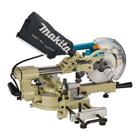
Slide compound saw
Hide thumbs
Also See for LS0714:
- Instruction manual (144 pages) ,
- Technical information (26 pages) ,
- Parts breakdown (6 pages)
Table of Contents

Related Manuals for Makita LS0714


Summary of Contents for Makita LS0714
- Page 1 Slide Compound Saw MODEL LS0714 MODEL LS0714F MODEL LS0714FL MODEL LS0714L 005515 DOUBLE INSULATION I N S T R U C T I O N M A N U A L WARNING: For your personal safety, READ and UNDERSTAND before using.
-
Page 2: Specifications
Dimensions (L x W x H) ..................... 670 mm x 430 mm x 458 mm Net weight ..........LS0714: 12.5 kg, LS0714F: 12.8 kg, LS0714FL: 13.1 kg, LS0714L: 13.0 kg • Due to our continuing programme of research and development, the specifications herein are subject to change without notice. - Page 3 Intended use EC-DECLARATION OF CONFORMITY The tool is intended for accurate straight and miter cut- Model; LS0714, LS0714F, LS0714L, LS0714FL ting in wood. With appropriate saw blades, aluminum We declare under our sole responsibility that this prod- can also be sawed.
-
Page 4: Safety Instructions
SAFETY INSTRUCTIONS ENA001-2 WARNING: When using electric tools, basic safety precautions, including the following, should always be followed to reduce the risk of fire, electric shock and personal injury. Read all these instructions before operating this product and save these instructions. For safe operations: safer performance. -
Page 5: Additional Safety Rules For Tool
ADDITIONAL SAFETY RULES FOR TOOL ENB034-3 21. Before using the tool on an actual workpiece, let it Wear eye protection. run for a while. Watch for vibration or wobbling that Keep hands out of path of saw blade. Avoid con- could indicate poor installation or a poorly balanced tact with any coasting blade. -
Page 6: Blade Guard
INSTALLATION Bench mounting When the tool is shipped, the handle is locked in the lowered position by the 003923 stopper pin. Release the stopper pin by lowering the handle slightly and pulling the stopper pin. 1. Stopper pin This tool should be bolted with two bolts to a level and stable surface using the 003924 bolt holes provided in the tool’s base. - Page 7 For European countries 006661 When lowering the handle, the blade guard A rises automatically. The blade guard B rises as it contacts a workpiece. The guards are spring loaded so it returns to its original position when the cut is completed and the handle is raised.
-
Page 8: Maintaining Maximum Cutting Capacity
Positioning kerf board 003926 This tool is provided with the kerf boards in the turn base to minimize tearing on the exit side of a cut. The kerf boards are factory adjusted so that the saw blade does not contact the kerf boards. Before use, adjust the kerf boards as follows: First, unplug the tool. - Page 9 Stopper arm 003928 The lower limit position of the blade can be easily adjusted with the stopper arm. To adjust it, move the stopper arm in the direction of the arrow as shown in the figure. Adjust the adjusting screw so that the blade stops at the desired position when lowering the handle fully.
-
Page 10: Switch Action
Adjusting the bevel angle 003930 To adjust the bevel angle, loosen the lever at the rear of the tool counterclock- wise. Push the handle to the left to tilt the saw blade until the pointer points to the desired angle on the bevel scale. Then tighten the lever clockwise firmly to secure the arm. - Page 11 2. Switch trigger simply pull the switch trigger without pressing the lock-off button. Return 3. Handle tool to a Makita service center for proper repairs BEFORE further usage. • NEVER tape down or defeat purpose and function of lock-off button.
- Page 12 Laser beam action For model LS0714FL, LS0714L 005519 CAUTION: • Never look into the laser beam. Direct laser beam may injure your eyes. For European countries only CAUTION: • LASER RADIATION, DO NOT VIEW DIRECTLY WITH OPTICAL INSTRUMENTS, CLASS 1M LASER PRODUCT. 1.
- Page 13 Always be sure that the tool is switched off and unplugged before installing or removing the blade. • Use only the Makita socket wrench provided to install or remove the blade. Failure to do so may result in overtightening or insufficient tightening of the hex bolt. This could cause an injury.
- Page 14 Press the shaft lock to lock the spindle and use the socket wrench to loosen 003935 the hex bolt clockwise. Then remove the hex bolt, outer flange and blade. 1. Shaft lock 2. Arrow 3. Blade case 4. Socket wrench 5.
- Page 15 NOTE: If you connect a Makita vacuum cleaner to this tool, more efficient and cleaner 1. Dust box operations can be performed. 2. Cover 3.
-
Page 16: Securing Workpiece
Securing workpiece WARNING: • It is extremely important to always secure the workpiece properly and tightly with the vise. Failure to do so can cause the tool to be damaged and/or the workpiece to be destroyed. PERSONAL INJURY MAY ALSO RESULT. -
Page 17: Operation
could cause the workpiece to be thrown, cause damage to the blade or cause the loss of control, which can result in PERSONAL INJURY. Holders and holder assembly (optional accessories) 002247 The holders and the holder assembly can be installed on either side as a con- venient means of supporting workpieces horizontally. - Page 18 Press cutting (cutting small workpieces) 005524 Workpieces up to 50 mm high and 97 mm wide can be cut in the follow- ing way. Push the carriage toward the guide fence fully and tighten two clamp screws which secure the slide poles clockwise to secure the carriage. Secure the workpiece with the vise.
- Page 19 Bevel cut 005526 Loosen the lever and tilt the saw blade to set the bevel angle (Refer to the previously covered “Adjusting the bevel angle”). Be sure to retighten the lever firmly to secure the selected bevel angle safely. Secure the workpiece with a vise.
- Page 20 Wood facing Use of wood facing helps to assure splinter-free cuts in workpieces. Attach a wood facing to the guide fence using the holes in the guide fence. See the figure concerning the dimensions for a suggested wood facing. 002206 Over 15mm (5/8”) Over 420mm (16-1/2”) 50mm-60mm...
-
Page 21: Maintenance
Carrying tool 003923 Make sure that the tool is unplugged. Secure the blade at 0° bevel angle and the turn base at right miter angle fully. Secure the slide poles after pulling the carriage toward the guide fence fully. Lower the handle fully and lock it in the lowered position by pushing in the stopper pin. - Page 22 Lower the handle fully and lock it in the lowered position by pushing in 002209 the stopper pin. Square the side of the blade with the face of the guide fence using a triangular rule, try-square, etc. Then securely tighten the hex bolts on the guide fence in the order from the right side.
- Page 23 3. Holder assembly a short life of the tool. (optional accessory) • Have the tool repaired by Makita authorized service center for any failure on the laser unit. No change with different type of laser is permitted. 005702 1. Vertical vise 2.
- Page 24 When adjusting the laser line appears on the left side of the saw blade 005527 1. Screw to change the movable 2. Adjusting screw range of the adjusting screw 3. Hex wrench 4. Laser line 5. Saw blade When adjusting the laser line appears on the right side of the saw blade 005528 1.
- Page 25 Remove screws, which secure Lamp Box for the light. Pull out the Lamp Box keeping pushing lightly the upper position of it as illus- trated on the left. Pull out the fluorescent tube and then replace it with Makita original new one.
- Page 26 Cleaning of the lens for the laser light 005703 For model LS0714FL, LS0714L If the lens for the laser light becomes dirty, or sawdust adheres to it in such a way that the laser line is no longer easily visible, unplug the saw and remove and clean the lens for the laser light carefully with a damp, soft cloth.
-
Page 27: After Use
CAUTION: • These accessories or attachments are recommended for use with your Makita tool specified in this manual. The use of any other accessories or attachments might present a risk of injury to persons. Only use accessory or attachment for its stated purpose. - Page 28 Makita Corporation Anjo, Aichi, Japan 884547D226...