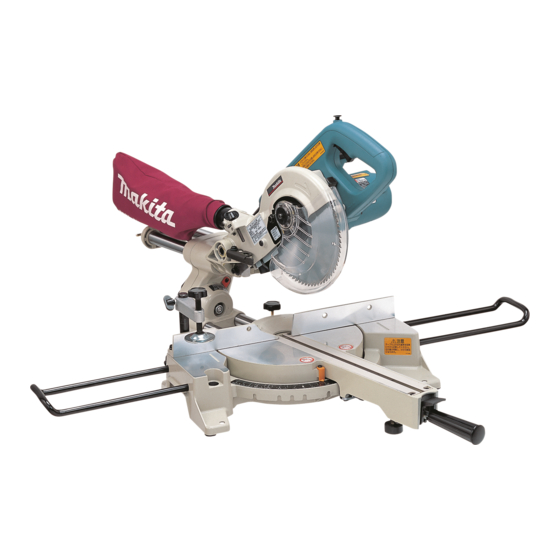
Makita LS0714 Technical Information
Slide compound saw 190mm
Hide thumbs
Also See for LS0714:
- Instruction manual (144 pages) ,
- Parts breakdown (6 pages) ,
- Instruction manual (31 pages)
Advertisement
Quick Links
Download this manual
See also:
Instruction Manual
T
ECHNICAL INFORMATION
Models No.
Description
C
ONCEPT AND MAIN APPLICATIONS
New slide compound saw model LS0714 has been developed to
improve cost-effectiveness by removing electronic circuit for soft start &
constant speed from model LS0713.
The primary use is for making/modifying interior decorations in apartment
building. Model LS0714's compact design and light weight are
convenient to carry to workplace.
The LS0714 series is available in the following variations:
*LS0714:With neither Fluorescent job light nor Laser marker
*LS0714F:With Fluorescent job light for cutting workpiece in dark places
*LS0714FL:With Fluorescent job light and Laser marker for easy trace of
cutting line
*LS0714L:With Laser marker
S
pecification
Voltage (V)
110
120
220
230
240
Model No.
Diameter: mm ( " )
Saw blade
Hole diameter: mm ( " )
No load speed: min-
Fluorescent job light
Laser marker
Lock-off botton for trigger switch
Electric brake
Protection against electric shock
Power supply
cord: m ( ft )
Net weight: kg ( lbs )
Cutting capacity: mm ( " )
90°
Miter angle
45° Left and Right
57° Right
LS0714, LS0714F, LS0714FL, LS0714L
Slide Compound Saw 190mm (7-1/2")
Cycle (Hz)
Current (A)
9.7
50 / 60
10.0
50 / 60
50 / 60
4.8
50 / 60
4.6
50 / 60
4.4
20 (13/16) [Canada, Chile, Colombia, Mexico, Panama, USA: 15.88 (5/8)]
= rpm.
1
Australia
Except Australia
12.5 (27.6)
Bevel angle
With a 20mm
(1-3/4 x 10-3/8)
auxiliary wood fence
(1-9/16 x 11-3/4)
With a 15mm
(1-3/4 x 7-1/4)
auxiliary wood fence
(1-9/16 x 8-3/8)
With a 10mm
auxiliary wood fence
Continuous Rating (W)
Input
1,010
1,010
1,010
1,010
LS0714
LS0714F
190 (7-1/2)
No
Yes
No
No
( for Canada and USA: Yes)
Double insulation
12.8 (28.2)
45° Left
45 x 265
(2-3/8 x 10-3/8)
40 x 300
(2-1/16 x 11-3/4)
45 x 185
(2-3/8 x 7-1/4)
40 x 212
(2-1/16 x 8-3/8)
(2-3/8 x 5-3/4)
(2-1/16 x 6-3/8)
Dimensions : mm ( " )
Length ( L )
670 (26-3/8)
Width (W )
Height ( H )
Max. Output(W)
Output
450
500
450
450
450
LS0714FL
6,000
Yes
Yes
Yes
No
2.0 (6.6)
2.5 (8.2)
13.1 (28.9)
90°
60 x 265
52 x 300
40 x 300
(1-9/16 x 11-3/4)
60 x 185
52 x 212
60 x 145
52 x 163
PRODUCT
P 1 / 26
430 (17)
458 (18)
1,200
1,200
1,200
1,200
1,200
LS0714L
No
Yes
12.8 (28.2)
5° Right
Advertisement

Related Manuals for Makita LS0714


Summary of Contents for Makita LS0714
- Page 1 Description Slide Compound Saw 190mm (7-1/2") ONCEPT AND MAIN APPLICATIONS New slide compound saw model LS0714 has been developed to improve cost-effectiveness by removing electronic circuit for soft start & constant speed from model LS0713. The primary use is for making/modifying interior decorations in apartment building.
-
Page 2: Standard Equipment
P 2 / 26 tandard equipment T.C.T. Saw blade 190mm ....... 1 pc Holder set (2 pcs. in set) ......... 1 set Socket wrench 10 ........... 1 pc Triangular rule ............1 pc Dust bag ............1 pc Hex wrench 2.5 (LS0714FL/ LS0714L only)..1 pc Vertical vise ........... - Page 3 Remove the following parts from the machine for safety before repair/ maintenance: *Saw Blade *Inner Flange *Outer Flange *Dust Nozzle [1] Lubrication 1. Apply Makita grease N. No.1 to the following portions designated by black triangle to protect parts and product from unusual abrasion. See Fig. 1. Item No.
- Page 4 P 4 / 26 epair 2. Apply Makita grease N. No.1 to the following portions designated by black triangle to protect parts and product from unusual abrasion. See Fig. 2. Item No. Parts item Portion to lubricate Spiral spring 26 Whole...
- Page 5 P 5 / 26 epair [2] Removing motor unit (blade case, motor housing, handle etc.) from front arm complete 1. Remove safety cover section from blade case as illustrated in Fig. 3-1, Fig.3-2 and Fig.3-3. Fig. 3-1 Fig. 3-2 Hex bolt M6x14 Stopper pin Center cover Knob 20...
- Page 6 P 6 / 26 epair 3. While holding the motor unit with your hand, pull out knob 20 for stopper pin to release the lock of motor unit, and lift up the motor unit slowly until it comes to the free point from return force of torsion spring 28. See Fig. 3-5. 4.
- Page 7 P 7 / 26 epair [5]Adjusting the return force of torsion spring 28 1. Torsion spring 28 should be adjusted so that motor unit can smoothly return to the initial raised position from any other place. Turning hex socket head set screw M6x16 with hex wrench allows to adjust the return force. See Fig. 5. Fig.
- Page 8 P 8/ 26 epair [7] Assembling safety cover section 1. Insert the tail portion of spiral spring 26 into the elliptical hole of safety cover. See Fig. 7-1. 2. Mount center washer to safety cover by aligning its holes with four bosses of safety cover. See Fig. 7-2. 3.
- Page 9 P 9/ 26 epair [8] Removing turn base from base 1. Remove guide fence and kerf board. See Fig. 8-1. 2. Remove hex lock nut M8-13 using socket wrench.And then, remove turn base from base while pushing lock lever in the direction designated with arrow.
- Page 10 P 10/ 26 epair [9] Mounting turn base to base 1. Apply grease to slide plate and boss for accepting the turn base's axis. Refer to Fig. 2. 2. Fasten hex lock nut M8-13 so that the turn base can move smoothly without wobbling. Refer to Fig. 8-2. [10] Mounting square rod and securing ring 26 1.
- Page 11 P 11/ 26 epair [11] Disassembling positive lock mechanism of turn base 1. Remove grip 32. 2. Separate lock lever plate and lock lever from turn base by removing tapping screw bind CT 4x16. See Fig. 10-1. 3. Turn lock pin in order to face pin 3 to vertical direction. And remove pin 3 while pushing compression spring 6 toward the grip side.
- Page 12 P 12/ 26 epair [13] Mounting stopper plate to arm holder Mount stopper plate as illustrated in Fig. 12. Fig. 12 Insert this tail into the small hole Arm holder of stopper plate. Stopper plate Arm holder Stopper plate Pan head screw M5 Flat washer 6 Flat washer 6 Torsion...
- Page 13 [16] Angle adjustment of saw blade 1. Adjust the angle of saw blade at 90° against turn base using 90 degrees set square (Makita Part No.1R208). See Fig. 15-1. While keeping this condition, fix the angle by adjusting 0° degrees bevel angle adjusting bolt at the side of arm. See Fig. 15-2.
- Page 14 P 14/ 26 epair [18] Angle adjustment of guide fence 1. Provisionally tighten a M6x25 hex bolt into screw hole A on the operator's left side of guide fence as Fig. 17. 2. While checking the angle of guide rule to saw blade using 90 degrees set square (No.1R208), adjust the guide fence by moving its right end until the angle sets at 90 degrees.
- Page 15 P 15/ 26 epair 7. Laser section can be disassembled as shown in Fig. 18-3. Fig. 18-3 1) Unscrewing pan head screw M3x10 allows to remove torsion spring 9 and laser circuit. Block C Torsion spring 9 Pan head screw Block B Laser circuit M3x10...
- Page 16 (2) Precise adjustment of laser line Jig for laser line adjustment 1. Lock the motor unit at the initial position.Mount " " (Makita part No. 1R315) to spindle and drive hex bolt M6x18 into the screw hole of spindle head. See Fig. 20-2. Fig. 20-2...
- Page 17 P 17/ 26 epair 2. Make precise adjustment so that the laser line should be aligned with the line of jig for laser line adjustment (1R315) when lowering the jig until it reaches the pan head screw M5x16 of link plate side. See Fig. 20-3. Fig.
- Page 18 P 18/ 26 epair (3) Adjustment of laser beam positioning (exclusively for LS0714FL/ LS0714L) For safety and easy adjusting work, remove saw blade, safety cover section, flanges (outer and inner) and dust nozzle. Jig for laser line adjustment (1R315) 1. Mount to spindle.
- Page 19 P 19/ 26 epair 7. Lift up the jig until it reach the pan head screw M5x16 of laser box side. See Fig. 20-4. 8.Adjust the laser line so as to parallel the line of jig by turning hex socket set screw M4x6 (B). See Fig. 20-7. Fig.
- Page 20 P 20/ 26 epair 10. Lower the jig again until it reaches the pan head screw M5x16 of link plate side. See Fig. 20-6. 11. Align the laser line with the line of jig by turning hex socket set screw M4x6 (A). See Fig. 20-9. Fig.
-
Page 21: Circuit Diagram
P 21/ 26 iriing of Lead Wire to Terminal Block (For all the subject models) Powers supply cord When connecting power supply cord with electrical parts in handle, strip the power supply cord to expose 50mm up to 70mm of one inner lead wire for Terminal block connecting with Terminal as illustrated to right. - Page 22 P 22/ 26 iring diagram in Handle L LS0714FL (with Fluorescent light and laser marker) Receptacles for connecting to laser switch Printed wiring board Power supply cord Rib D Main switch Noise suppressor Connector Rib C Punched hole Terminal block Rib B Rib A Motor housing...
- Page 23 P 23/ 26 ircuit diagram LS0714F (with Fluorescent light) Color index of lead wires' sheath Black Orange White Blue Brush Brush holder A holder B (7) Light assembly (3) Insulated connector (1) Power supply cord (5) Terminal block (8) Support complete (4) Noise suppressor (2) Main switch (6) Connectors...
- Page 24 P 24/ 26 ircuit diagram LS0714 (without Fluorescent light and laser) Color index of lead wires' sheath Black White Orange Brush Brush holder A holder B (1) Power supply cord (2) Main switch (3) Noise suppressor (4) Support complete iring diagram in handle L...
- Page 25 P 25/ 26 ircuit diagram LS0714L (with laser marker) Color index of lead wires' sheath Black Orange White Blue Brush Brush holder A holder B Laser section (11) (13) (12) Power source (10) (1) Power supply cord (5) Terminal block (9) Laser switch (13) Laser circuit (2) Main switch...
- Page 26 P 26/ 26 iring diagram in Handle L LS0714L (with laser marker) Powers supply cord When connecting power supply cord with electrical parts in handle, strip the power supply cord to expose 50mm up to 70mm of one inner lead wire for Terminal block connecting with Terminal as illustrated to right.