Table of Contents
Advertisement
Quick Links
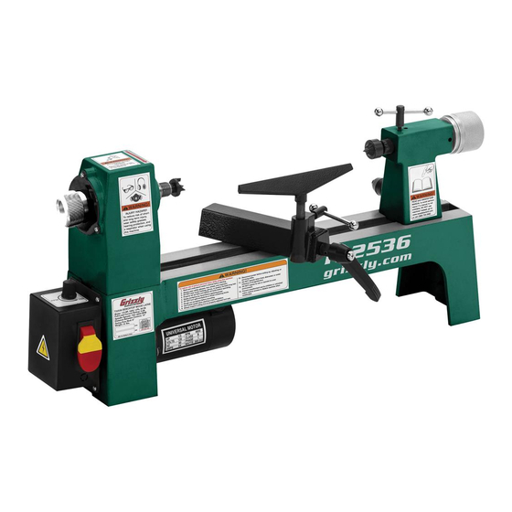
MODEL T32536
8" X 13" BENCHTOP
WOOD LATHE
OWNER'S MANUAL
(For models manufactured since 10/20)
COPYRIGHT © DECEMBER, 2020 BY GRIZZLY INDUSTRIAL, INC.
WARNING: NO PORTION OF THIS MANUAL MAY BE REPRODUCED IN ANY SHAPE
OR FORM WITHOUT THE WRITTEN APPROVAL OF GRIZZLY INDUSTRIAL, INC.
#KS21559 PRINTED IN CHINA
V1.12.20
Advertisement
Table of Contents

Related Manuals for Grizzly T32536


Summary of Contents for Grizzly T32536
- Page 1 (For models manufactured since 10/20) COPYRIGHT © DECEMBER, 2020 BY GRIZZLY INDUSTRIAL, INC. WARNING: NO PORTION OF THIS MANUAL MAY BE REPRODUCED IN ANY SHAPE OR FORM WITHOUT THE WRITTEN APPROVAL OF GRIZZLY INDUSTRIAL, INC. #KS21559 PRINTED IN CHINA V1.12.20...
- Page 2 This manual provides critical safety instructions on the proper setup, operation, maintenance, and service of this machine/tool. Save this document, refer to it often, and use it to instruct other operators. Failure to read, understand and follow the instructions in this manual may result in fire or serious personal injury—including amputation, electrocution, or death.
-
Page 3: Table Of Contents
Table of Contents INTRODUCTION ..........2 SECTION 5: ACCESSORIES ......29 Contact Info............ 2 SECTION 6: MAINTENANCE ......31 Manual Accuracy ........... 2 Schedule ............31 Identification ........... 3 Cleaning & Protecting ........31 Controls & Components ......... 4 Lubrication ........... 31 Glossary of Terms ......... -
Page 4: Introduction
ID label (see below). This information is required for us to provide proper tech support, and it helps us determine if updated documenta- tion is available for your machine. Manufacture Date Serial Number Model T32536 (Mfd. Since 10/20) -
Page 5: Identification
Tighten all locks before operating. d) Rotate workpiece by hand before applying power. e) Rough out workpiece before installing on faceplate. f) DO NOT mount split workpiece or one containing knot. g) Use lowest speed when starting new workpiece. Model T32536 (Mfd. Since 10/20) -
Page 6: Controls & Components
Turns lathe motor ON and OFF. Remove ting tools. yellow disabling key to prevent unauthorized operation of machine. Tool Rest Lock Handle: Secures tool rest in position. Tool Rest Base (Banjo) Lock Lever: Secures tool rest base in position along bed. Model T32536 (Mfd. Since 10/20) -
Page 7: Glossary Of Terms
The following is a list of common definitions, terms and phrases used throughout this manual as they relate to this lathe and woodworking in general. Become familiar with these terms for assembling, adjusting or operating this machine. Your safety is VERY important to us at Grizzly! Bed: The long, rail-like metal base to which... -
Page 8: Machine Data Sheet
MACHINE DATA SHEET Customer Service #: (570) 546-9663 · To Order Call: (800) 523-4777 · Fax #: (800) 438-5901 MODEL T32536 8" X 13" BENCHTOP WOOD LATHE Product Dimensions: Weight................................41 lbs. Width (side-to-side) x Depth (front-to-back) x Height..............29 x 10-1/2 x 13 in. - Page 9 The information contained herein is deemed accurate as of 1/15/2021 and represents our most recent product specifications. Model T32536 PAGE 2 OF 2 Due to our ongoing improvement efforts, this information may not accurately describe items previously purchased. Model T32536 (Mfd. Since 10/20)
-
Page 10: Section 1: Safety
Never operate under the influence of drugs or injury or blindness from flying particles. Everyday alcohol, when tired, or when distracted. eyeglasses are NOT approved safety glasses. Model T32536 (Mfd. Since 10/20) - Page 11 Make sure they are properly installed, you experience difficulties performing the intend- undamaged, and working correctly BEFORE ed operation, stop using the machine! Contact our operating machine. Technical Support at (570) 546-9663. Model T32536 (Mfd. Since 10/20)
-
Page 12: Additional Safety For Wood Lathes
Never standing to side of lathe until workpiece reaches completely wrap sandpaper around workpiece. full speed and you can verify safe rotation. -10- Model T32536 (Mfd. Since 10/20) -
Page 13: Section 2: Power Supply
-11- Model T32536 (Mfd. Since 10/20) - Page 14 Two-prong outlets do not meet the grounding requirements for this machine. Do not modify or use an adapter on the plug provided—if it will not fit the outlet, have a qualified electrician install the proper outlet with a verified ground. -12- Model T32536 (Mfd. Since 10/20)
-
Page 15: Section 3: Setup
Grizzly or the shipping agent. You MUST have the original pack- Box 1 (Figure 5) aging to file a freight claim. -
Page 16: Cleanup
NOTICE Avoid harsh solvents like acetone or brake parts cleaner that may damage painted sur- faces. Always test on a small, inconspicu- ous location first. -14- Model T32536 (Mfd. Since 10/20) -
Page 17: Assembly
Install tool rest base lock lever and M6-1 x 28 tool rest lock handle (see Figure 8). Tool Rest Lock Handle Tool Rest Base Lock Lever Figure 8. Hardware installed in tool rest base. -15- Model T32536 (Mfd. Since 10/20) -
Page 18: Test Run
Turn spindle speed dial all the way counter- feature is not working correctly. Call Tech clockwise to help prevent accidental start-up. Support for help. Connect machine to power supply. Congratulations! The Test Run is complete. -16- Model T32536 (Mfd. Since 10/20) -
Page 19: Section 4: Operations
Read books/magazines or get formal training before beginning any proj- ects. Regardless of the content in this sec- tion, Grizzly Industrial will not be held liable for accidents caused by lack of training. -17- Model T32536 (Mfd. Since 10/20) -
Page 20: Workpiece Inspection
• Wet or "Green" Stock: Turning wood with a moisture content over 20% can cause Tailstock increased wear on tooling. Clamp Nut Figure 12. Location of tailstock clamp nut. -18- Model T32536 (Mfd. Since 10/20) -
Page 21: Adjusting Tool Rest
BEFORE cutting, and cutting tool Position tool rest in desired location. is properly positioned to cut at the correct angle for tool and operation type. Retighten tool rest lock handle to secure tool rest in position. -19- Model T32536 (Mfd. Since 10/20) -
Page 22: Installing/Removing Headstock Center
Headstock Center Spindle Figure 14. Installing center in headstock spindle. Make sure center is securely installed by attempting to pull it out by hand. A properly installed center will not pull out easily. -20- Model T32536 (Mfd. Since 10/20) -
Page 23: Installing/Removing Tailstock Center
Otherwise, workpiece can be Make sure center is securely installed by thrown from lathe, causing serious personal attempting to pull it out by hand—a properly injury or death. installed center will not pull out easily. -21- Model T32536 (Mfd. Since 10/20) -
Page 24: Installing/Removing Faceplate
Insert knockout tool into one hole on spindle, then tighten faceplate with open-end wrench (see Figure 18). Faceplate Figure 18. Installing faceplate on spindle. -22- Model T32536 (Mfd. Since 10/20) -
Page 25: Adjusting Spindle Speed
Starting lathe at highest speed, or too The Model T32536 utilizes a spindle speed dial fast of spindle speed may lead to workpiece (see Figure 19) that allows for on-the-fly spindle breaking loose or being thrown from lathe speed changes from 750 to 3200 RPM. -
Page 26: Spindle Turning
Drill Bit ⁄ " ............1 ing safer and easier when roughing out Tablesaw/Bandsaw ..........1 workpiece (see Figure 23). Corners Workpiece Removed Center Figure 23. Corners of workpiece removed. -24- Model T32536 (Mfd. Since 10/20) - Page 27 11. Properly adjust tool rest to workpiece (see Adjusting Tool Rest on Page 19). -25- Model T32536 (Mfd. Since 10/20)
-
Page 28: Faceplate Turning
(refer to Installing Faceplate on Page 22). — If wood screws cannot be placed in workpiece, faceplate can be mounted to a backing block attached to workpiece (see Mounting Workpiece on Backing Block on next page). -26- Model T32536 (Mfd. Since 10/20) -
Page 29: Sanding/Finishing
Mounting Follow under ing workpiece and may Workpiece on Faceplate (see Page 26) to cause serious injury. attach backing block to faceplate. Never wrap sandpa- per or finishing materi- Workpiece als completely around workpiece. -27- Model T32536 (Mfd. Since 10/20) -
Page 30: Selecting Turning Tools
The Swan Neck Hollowing Tool shown on Page 29 is a good example of a speciality tool. Figure 30. Example of a skew chisel. -28- Model T32536 (Mfd. Since 10/20) -
Page 31: Section 5: Accessories
" serious personal injury or machine damage. Round Scraper. Overall lengths are 16" to 19". To reduce this risk, only install accessories recommended for this machine by Grizzly. NOTICE Refer to our website or latest catalog for additional recommended accessories. - Page 32 ⁄ " in diameter. Marking two opposite diagonal lines determines the center point. Figure 37. Model T25802 Woodworking Calipers 5-Pc. Set. Figure 39. Model D3098 Center Finder. www.grizzly.com 1-800-523-4777 order online at or call -30- Model T32536 (Mfd. Since 10/20)
-
Page 33: Section 6: Maintenance
DO NOT allow any oil or grease to get on the inside mating surfaces of the quill. -31- Model T32536 (Mfd. Since 10/20) -
Page 34: Section 7: Service
6. Motor mount loose/broken. 6. Tighten/replace. 7. Workpiece/faceplate at fault. 7. Center workpiece in chuck/faceplate; reduce RPM; replace defective chuck. 8. Motor bearings at fault. 8. Test by rotating shaft; rotational grinding/loose shaft requires bearing replacement. -32- Model T32536 (Mfd. Since 10/20) - Page 35 Quill will not move 1. Keyway is not aligned with quill lock lever. 1. Align quill keyway and quill lock lever and slightly forward when knob tighten lever to engage keyway (Page 21). is turned. -33- Model T32536 (Mfd. Since 10/20)
-
Page 36: Tensioning & Replacing Belt
Figure 41. Location of motor mounting plate. ⁄ " Deflection Pulley Figure 43. Testing for ⁄ " belt deflection. Re-install spindle adjustment knob, then re- install outboard spindle plate using (3) M4-.7 x 8 Phillips head screws. -34- Model T32536 (Mfd. Since 10/20) -
Page 37: Aligning Pulleys
(3) M4-.7 there should be no unusual or pulsing sounds x 8 Phillips head screws. coming from the belt. Tighten set screw on spindle pulley. Install spindle adjustment knob and outboard spindle plate. -35- Model T32536 (Mfd. Since 10/20) -
Page 38: Replacing Fuse
Remove old fuse from holder and install new fuse. Re-install fuse holder in switch box. Brush Cap (1 of 2) Figure 46. Location of motor brushes. Replace both motor brushes and re-install brush caps. -36- Model T32536 (Mfd. Since 10/20) -
Page 39: Section 8: Wiring
Technical Support at (570) 546-9663. The photos and diagrams included in this section are best viewed in color. You can view these pages in color at www.grizzly.com. -37- Model T32536 (Mfd. Since 10/20) -
Page 40: Wiring Diagram
Disconnect power before working on wiring! Figure 47. Switch box wiring. Neutral 110 VAC 5-15 Plug Ground FUSE 10A – CIRCUIT BOARD Ground 120V MOTOR VARIABLE SPEED DIAL READ ELECTRICAL SAFETY -38- Model T32536 (Mfd. Since 10/20) ON PAGE 37! -
Page 41: Section 9: Parts
SECTION 9: PARTS We do our best to stock replacement parts when possible, but we cannot guarantee that all parts shown are available for purchase. Call (800) 523-4777 or visit www.grizzly.com/parts to check for availability. Main 68-1 68-2 41-1 61 62 41-2 BUY PARTS ONLINE AT GRIZZLY.COM! - Page 42 PT32536107 MODEL NUMBER LABEL 41-2 PT32536041-2 BRUSH CAP PT32536108 GRIZZLY.COM LABEL PT32536043 EXT RETAINING RING 10MM PT32536109 TOUCH-UP PAINT, GRIZZLY GREEN BUY PARTS ONLINE AT GRIZZLY.COM! -40- Model T32536 (Mfd. Since 10/20) Scan QR code to visit our Parts Store.
-
Page 43: Warranty & Returns
WARRANTY & RETURNS Grizzly Industrial, Inc. warrants every product it sells for a period of 1 year to the original purchaser from the date of purchase. This warranty does not apply to defects due directly or indirectly to misuse, abuse, negligence, accidents, repairs or alterations or lack of maintenance.