Table of Contents
Advertisement
Quick Links
model g9036
13" x 40" gear-head lathe
oWner's manual
Copyright © MAy, 2008 By grizzly industriAl, inC. revised August, 2009 (tr)
Warning: no portion of this manual may be reproduced in any shape
or form Without the Written approval of grizzly industrial, inc.
(For Models MAnuFACtured sinCe 7/08) #tr10672 printed in ChinA
Advertisement
Table of Contents

Related Manuals for Grizzly G9036


Summary of Contents for Grizzly G9036
- Page 1 13" x 40" gear-head lathe oWner's manual Copyright © MAy, 2008 By grizzly industriAl, inC. revised August, 2009 (tr) Warning: no portion of this manual may be reproduced in any shape or form Without the Written approval of grizzly industrial, inc.
- Page 2 This manual provides critical safety instructions on the proper setup, operation, maintenance and service of this machine/equipment. Failure to read, understand and follow the instructions given in this manual may result in serious personal injury, including amputation, electrocution or death. The owner of this machine/equipment is solely responsible for its safe use.
-
Page 3: Table Of Contents
table of contents introduction ..........2 section 6: maintenance ......43 Foreword ............2 schedule ............43 Contact info............ 2 Cleaning ............43 Machine description ........2 unpainted Cast iron ........43 identification ........... 3 Ball Fitting lubrication ......... 44 Machine data sheet ........ -
Page 4: Introduction
We are proud to offer the Model g9036. this the primary purpose of the metal lathe is to machine is part of a growing grizzly family of fine make concentric cuts in metal stock. With the metalworking machinery. When used according... -
Page 5: Identification
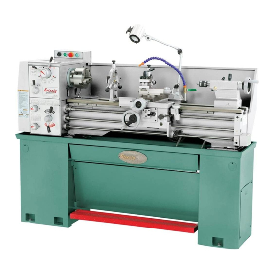
identification 3-Jaw Chuck lamp steady rest Control panel Coolant nozzle spindle speed levers tool post Feed direction Compound slide lever Cross slide tailstock thread dial Carriage spindle lever half nut lever Feed Feed speed Change Controls lever Brake Model g9036 Mfg. 7/08+... -
Page 6: Machine Data Sheet
machine data sheet MACHINE DATA SHEET Customer Service #: (570) 546-9663 · To Order Call: (800) 523-4777 · Fax #: (800) 438-5901 MODEL G9036 13" X 40" GEAR-HEAD FLOOR LATHE Product Dimensions: Weight................................1320 lbs. Length/Width/Height......................... 71-1/2 x 30 x 53-1/2 in. Foot Print (Length/Width)......................... - Page 7 Headstock Info Spindle Bore............................1-7/16 in. Spindle Taper.............................MT#5 No Of Spindle Speeds............................8 Range Of Spindle Speeds............70, 115, 190, 300, 460, 755, 1255, 2000 RPM Spindle Type..........................D1-4 Camlock Spindle Bearings......................... Tapered Roller Tailstock Info Tailstock Travel............................3-3/8 in. Tailstock Taper............................MT#3 Tailstock Barrel Diameter........................1-1/4 in.
-
Page 8: Section 1: Safety
SECTION 1: SAFETY For Your Own Safety, Read Instruction Manual Before Operating this Machine The purpose of safety symbols is to attract your attention to possible hazardous conditions. This manual uses a series of symbols and signal words intended to convey the level of importance of the safety messages. -
Page 9: Safety Instructions For Machinery
Safety Instructions for Machinery 7. ONLY ALLOW TRAINED AND PROP- 16. REMOVE CHUCK KEYS OR ADJUSTING ERLY SUPERVISED PERSONNEL TO TOOLS. Make a habit of never leaving OPERATE MACHINERY. Make sure chuck keys or other adjustment tools in/on operation instructions are safe and clearly the machine—especially near spindles! understood. -
Page 10: Additional Safety For Metal Lathes
additional safety for metal lathes clearing chips. Metal chips can easily speed rates. operating the lathe at the cut bare skin—even through a piece of cloth. wrong speed can cause nearby parts to Avoid clearing chips by hand or with a rag. break or the workpiece to come loose, which use a brush or vacuum to clear metal chips. -
Page 11: Glossary Of Terms
Become familiar with these terms for assembling, adjusting or operating this machine. your safety is very important to us at grizzly! arbor: A machine shaft that supports a cutting headstock: the major lathe component that tool. -
Page 12: Section 2: Circuit Requirements
section 2: circuit reQuirements 220v operation minimum power cord requirements For 220v connection, use a stranded-copper flex- ible cord that meets the minimum specifications listed below, does not exceed 50 ft., and has an insulation type that starts with "s." A qualified electrician Must determine the best cord to use serious personal injury could occur if you in your environment depending on exposure to... -
Page 13: Section 3: Setup
section 3: setup setup safety items needed for setup the following items are needed to complete the this machine presents setup process, but are not included with your serious injury hazards machine: to untrained users. read through this entire manu- description al to become familiar with •... -
Page 14: Inventory
inventory After all the parts have been removed from the boxes, the following items should be included with your machine: mounted inventory components a. three-Jaw Chuck ........1 b. steady rest ..........1 c. Follow rest ..........1 d. Change gears 32t, 85t, 100t ..1 each loose inventory components e. -
Page 15: Site Considerations
site considerations Weight Load Physical Environment Refer to the Machine Data Sheet for the weight The physical environment where your machine of your machine. Make sure that the surface upon is operated is important for safe operation and which the machine is placed will bear the weight the longevity of its components. -
Page 16: Cleanup
cleanup Gasoline and petroleum products have low flash The unpainted surfaces of your machine are points and can explode coated with a heavy-duty rust preventative that or cause fire if used to prevents corrosion during shipment and storage. clean machinery. Avo i d u sing t h e s e p r o du c t s This rust preventative has been your machine's to cl e a n m ac hin e r y. -
Page 17: Lifting & Moving
lifting & moving additional cleaning tips • For thorough cleaning, remove the steady rest, tool post, compound slide, and change- gears. • use a stiff brush when cleaning the threads on the leadscrew. • Move the slides and tailstock back and forth to thoroughly clean/lubricate underneath them. -
Page 18: Mounting Lathe
mounting lathe check gearbox oil in order to produce accurate work, the lathe must it is critical that you make sure there is oil in the sit level on the floor. Below are the most common headstock and apron gearboxes before proceed- ing with the test run. - Page 19 Make sure all tools and objects used during Move the spindle speed levers to 70 rpM (figure 13). setup are cleared away from the machine. disengage the half nut lever and the feed lever (figure 12), and make sure the saddle lock bolt is loosened (do not loosen the sad- dle lock bolt too much—see page 52).
-
Page 20: Spindle Break-In
12. reset the stop button. push down on the spindle lever to start spin- dle rotation counterclockwise. let the lathe 13. Make sure the lamp works. run for a minimum of 10 minutes. 14. If you do not have cutting fluid at this time, stop the spindle and disconnect the machine skip this step. -
Page 21: Section 4: Operation
training. -
Page 22: Feed Direction Lever
spindle speed levers Compound slide the spindle speed levers (figure 14) control the handwheel speed that the spindle rotates. the chart below the levers indicates the different lever configura- tions required to make the spindle rotate at vari- ous speeds. never move this lever while the spindle is moving. -
Page 23: Spindle Lever
tailstock half nut handwheel lever Quill lock lever Feed Change lever tailstock spindle lever lock lever figure 17. Carriage lever controls. figure 18. tailstock controls. spindle lever tailstock handwheel the spindle lever (figure 17) is primarily used to turning the tailstock handwheel (figure 18) start and stop the spindle and leadscrew in either advances or retracts the barrel in the tailstock. -
Page 24: Chuck & Faceplate Mounting
chuck & faceplate removal disConneCt lAthe FroM poWer! mounting lay a chuck cradle (see figure 20) or a layer of plywood over the bedways to protect the this lathe is shipped with the 3-jaw chuck installed, precision ground surfaces from damage and but includes a four jaw chuck kit and 12"... - Page 25 installation using a dead blow hammer or other soft mal- let, lightly tap around the outer circumference disConneCt lAthe FroM poWer! of the chuck body to break the chuck free from the cam-locks and from the spindle nose lay a chuck cradle or a layer of plywood over taper.
-
Page 26: Three-Jaw Chuck
three-Jaw chuck lift the chuck, and insert the studs onto the spindle nose (see figure 24). While support- ing the weight of the chuck/faceplate, turn one cam with the chuck key until the cam line the three-jaw chuck included with this lathe is a is between the two v's on the spindle. -
Page 27: Four-Jaw Chuck
four-Jaw chuck rotate the jaw 180˚ and replace the cap screws. Make sure the longer cap screw remains in the thicker part of the jaw. repeat with the remaining jaws (figure 27). the four-jaw chuck included with this lathe fea- tures independently adjustable hardened steel jaws. -
Page 28: Faceplate
faceplate turn each jaw until it just makes contact with the workpiece. tighten each jaw in small increments. After the faceplate is used to turn non-cylindrical parts adjusting the first jaw, continue tightening in and for off-center turning. opposing sequence (see figures 28 & 29). Check frequently to make sure you have not wandered off your center point due to apply- to mount a workpiece on the faceplate:... -
Page 29: Centers
centers secure the workpiece with a minimum of three independent clamping devices (see figure 31). Failure to follow this step may lead to deadly injury to yourself or bystand- the Model g9036 lathe is supplied with two Mt#3 ers. take into account rotation and the cut- dead centers and a Mt#5-Mt#3 adapter sleeve to ting forces applied to the workpiece when fit Mt#3 centers into the spindle. -
Page 30: Mounting Center In Spindle
When a center is used in the spindle, the most lock the quill into place once the center and common application is using it with a faceplate the part rotate together. the quill may need (see figure 33). to be adjusted during operation. to remove a center, retract the quill until the center pops free. -
Page 31: Offsetting Tailstock
offsetting tailstock aligning tailstock the tailstock alignment was set at the factory with the tailstock can be offset slightly to cut shallow the headstock. however, we recommend that you tapers. to return the tailstock back to original take the time to ensure that the tailstock is aligned position, repeat the process until the centered to your own desired tolerances. - Page 32 Attach a lathe dog at the spindle end to the — if the stock is thinner at the tailstock end, bar stock from step 1 and mount it between the tailstock needs to be moved away from the centers (as shown in figure 38). the operator by at least the amount of the taper (figure 40).
-
Page 33: Drilling With Tailstock
drilling with coolant system tailstock the coolant system delivers cutting fluid via a positional nozzle. the coolant system is controlled the tailstock can be used to drill holes by mount- by a pump switch located on the control panel and ing a drill bit in the tailstock, rotating the workpiece a valve lever near the base of the nozzle (figure with the spindle, then using the tailstock quill... -
Page 34: Steady Rest
steady rest position the steady rest where desired. tighten the bolt at the base of the steady rest to secure in place. the steady rest serves as a support for long Close the steady rest so that the workpiece is shafts. -
Page 35: Tool Post
tool post spindle speed the tool post included with the Model g9036 is the correct spindle speed is determined by the a four-way tool post. the tool post is mounted on workpiece material, the type of tooling used, and the desired finish. refer the chart in figure 49 top of the compound slide, and allows a maximum of four tools to be loaded simultaneously. - Page 36 use the following formula to determine the With the calculated spindle speed, examine needed spindle speed for your operation: the spindle speed chart on the front of the headstock to find the closest match. Cutting Speed (SFM) x 4 Spindle Speed = note: In most cases the calculated spindle Diameter of Cut speed will be between the available speeds.
-
Page 37: Power Feed
power feed Move the feed direction lever to the desired longitudinal feed setting indicated by the arrow above the screw thread. Cross feed directions are as follows: when the arrow NOTICE points left, the cross feed is away from the spindle axis;... -
Page 38: Feed Rates
feed rates review the chart shown in figure 55 to determine the correct configuration for your desired feed rate. Feed rate is the speed the tooling travels during the chart shows two numbers separated by operation. When the power feed is used, the feed a slash in each box. -
Page 39: Thread Settings & Change Gears
thread settings & install the necessary change gears shown on the chart and position them so they mesh change gears where indicated (figure 58), but leaving 0.05"–0.08" backlash between gears. the Model g9036 is capable of cutting metric, inch, module, and diametral pitch threads. the Side Front View... -
Page 40: Threading Controls
threading controls half nut lever the half nut lever engages the carriage with the leadscrew. typically, the longitudinal handwheel must be moved slightly to help the half nut engage the purpose of this section is to orient you with on the leadscrew (figure 62). the controls used with threading and how to use the threading dial on this machine. - Page 41 to use the thread chart, find the tpi that you want A "1 or 3" means that you must engage the half to cut and reference the "scale" number(s) next to nut when the 1 or 3 scale mark lines up with the it.
-
Page 42: Section 5: Accessories
ACCessories section 5: accessories h6879—lathe operation & maintenance h6095—digital readout (dro) book this is one of the finest dro's on the market this detailed metal lathe book provides extensive today. Features selectable resolution down to coverage of a wide variety of metalworking opera- 5µm, absolute/incremental coordinate display, tions. - Page 43 h9240—Water soluable machining oil g0489—metalworking sander specially for metal workers, this sander uses 3" x rustlick water soluable machining oil contains effective chlorinated e.p. additive to provide excel- 79" long sanding belts designed resist overheat- lent tool life. guaranteed to protect neoprene ing.
- Page 44 Quick change tool holders g7038z—boring bar g7040—carbide inserts for steel (5 pk) All models are series 200 g7048—carbide inserts for cast iron (5 pk) g5701—boring bar holder ⁄ " g5704—parting tool holder ⁄ " g5705—Knurling tool holder ⁄ "~ ⁄ "...
-
Page 45: Section 6: Maintenance
section 6: maintenance cleaning always disconnect power from the machine before Cleaning the Model g9036 is relatively easy. performing maintenance. disconnect the lathe before cleaning it. remove ignoring this warning may chips as they accumulate. vacuum excess metal result in serious personal chips and wipe off the remaining coolant with a injury. -
Page 46: Ball Fitting Lubrication
ball fitting lubrication Wipe clean and lubricate the ball fittings with an iso 68 or equivalent oil. to insert the oil, depress the ball with the tip of an oil can and squirt once. Copy this page and use the photos and chart below as a weekly check-off list to maintain the recommended daily lubrication of the ball fittings. -
Page 47: V-Belt Tension
v-belt tension oil reservoirs the v-belts must be properly tensioned to ensure the headstock, gearbox, and apron have oil res- proper power transmission and machine func- ervoirs that must be checked and topped off, if tionality. the v-belts slightly stretch with use and necessary, on a daily basis. - Page 48 changing oil gearbox the oil in the reservoirs must be changed after Fill plug the first three months of operation, then annually after that. use an iso 68 or equivalent gear oil. reservoir approximate volume headstock......... 2.33 Quarts gearbox ..........1.16 Quarts Apron ..........
-
Page 49: Coolant System
coolant system inspect the level of cutting fluid inside the tank. the cutting fluid should be approxi- mately an inch below the top of the tank. using a flashlight, inspect the level of swarf inside the first chamber of the coolant tank. if the swarf level is beyond ⁄... -
Page 50: Section 7: Service
section 7: service troubleshooting review the troubleshooting and procedures in this section to fix your machine if a problem develops. if you need replacement parts or you are unsure of your repair skills, then feel free to call our technical support at (570) 546-9663. motor &... - Page 51 troubleshooting operation and Work results symptom possible Cause possible solution entire machine 1. Workpiece is unbalanced. 1. reinstall workpiece so it is as centered with the spindle bore as possible. vibrates excessively upon 2. Worn or broken gear present. 2. inspect gears and replace if necessary. startup and while 3.
-
Page 52: Cross Slide Backlash Adjustment
cross slide rotate the cross slide handle to feed the leadscrew nut out from under the cross slide backlash adjustment as shown in figure 88. leadscrew nut Backlash is the amount of play in a lead screw. it is felt when turning a handwheel in one direction, then turning it in the other direction. -
Page 53: Gib Adjustments
gib adjustments on the cross slide, moving the gib toward the back of the machine increases pressure and moving the gib toward the front of the machine decreases pressure. there are three main gib adjustments for the Model g9036: the cross-slide gib, the compound the gib is moved by rotating the screws at both slide gib and the saddle gib. -
Page 54: Half Nut Adjustment
half nut adjustment saddle gib the saddle is supplied with a lock bolt on the front right-hand side of the slide (see figure 91). this bolt locks the saddle in place for increased rigidity the half nut mechanism can be adjusted if it when making face cuts. -
Page 55: Shear Pin Replacement
shear pin bearing preload replacement this lathe is shipped from the factory with the the Model g9036 is shipped with two extra shear spindle bearing preload adjusted. if the spindle pins. the shear pins hold the leadscrew and feed ever develops a bit of end-play and the workpiece rods together (see figure 94). - Page 56 place the chuck key in the cam-lock socket place a dial indicator on the cross slide and to keep the spindle from rotating, and remove move the carriage toward the headstock until the outer spanner nut shown in figure 96. the contact point of the indicator touches the spindle face (figure 98).
-
Page 57: Tailstock Lock
tailstock lock since it takes great effort to turn the inner spanner nut, you may find it difficult to know if you have gone past the zero end-play point or not. it is easiest to have someone watch When pushed toward the spindle, the tailstock lock the dial while you tighten the inner spanner holds the tailstock firmly in place on the bedway nut. -
Page 58: Gap Removal
gap removal replacing v-belt A section of the bed called the "gap" is located tools needed just under the spindle and can be removed for phillips screwdriver #2 ........1 turning large diameter parts or when using a large Wrench 17mm............ 1 diameter faceplate. -
Page 59: Brake Pads
brake pads step off the brake and remove the pulley. figure 105 shows the pulley removed and the brake pads exposed. When the brake pads are worn down to within ⁄ " thick they must be replaced. if the brake pads Brake completely wear out, then metal will grind on pads... -
Page 60: Section 8: Wiring
Technical Support at (570) 546-9663. nents before completing the task. The photos and diagrams included in this section are best viewed in color. You can view these pages in color at www.grizzly.com. -58- Model g9036 Mfg. 7/08+... -
Page 61: Wiring Overview
Wiring overview ELECTRICAL PLUG (NOT INCLUDED) Ground BRAKE SWITCH 6-15 Plug (As Recommended) MAIN MOTOR PUMP LIGHT MOTOR SPINDLE SWITCH -59- READ ELECTRICAL SAFETY Model g9036 Mfg. 7/08+ ON PAGE PB! -
Page 62: Spindle Switch, Main Motor & Pump Motor
spindle switch, main motor & pump motor SPINDLE SWITCH Ground MAIN MOTOR Start Capacitor 150MFD 250VAC Ground Capacitor 20MFD 450VAC PUMP MOTOR U2W1 Z1V1 Ground -60- READ ELECTRICAL SAFETY Model g9036 Mfg. 7/08+ ON PAGE PB! -
Page 63: Electrical Box Wiring
electrical box Wiring STOP POWER COOLANT SWITCH BUTTON LIGHT PUMP SWITCH 21NC 21NC 13NO 23NO 33NO 43NO 110V Tianshui 213 Tianshui 213 Tianshui 213 GSC1-1201 110V GSC1-1201 110V JZC3-40d 110V CONTACTOR CONTACTOR CONTACTOR 14NO 24NO 34NO 44NO 22NC 22NC V12 Z11 Juche Juche JR29-16... -
Page 64: Electrical Box Photo
electrical box photo -62- READ ELECTRICAL SAFETY Model g9036 Mfg. 7/08+ ON PAGE PB! -
Page 65: Section 9: Parts
section 9: parts electrical breakdown 134 135 152-2 152-5 152-3 152-4 152-1 122-1 122-5 122-3 122-2 122-4 152-6 -63- Model g9036 Mfg. 7/08+... - Page 66 electrical parts list PART # DESCRIPTION PART # DESCRIPTION P9036122 MOTOR P9036138 BRAKE SWITCH 122-1 P9036122-1 FAN COVER P9036139 CORD COVER SMALL 122-2 P9036122-2 P9036140 CORD COVER LARGE 122-3 P9036122-3 S CAPACITOR 150M 250V 3" X 1-1/2" P9036141 PUMP MOTOR 122-4 P9036122-4 R CAPACITOR 20M 450V 3"...
-
Page 67: Bed Breakdown
bed breakdown 47A 49 -65- Model g9036 Mfg. 7/08+... -
Page 68: Bed Parts List
bed parts list REF PART # DESCRIPTION REF PART # DESCRIPTION P9036001 MOTOR BASE P4016242 PLUG P9036002 PULLEY P4016243 HEX SHAFT STUD P9036003 P9036044 COVER P9036004 P4016245 KNURLED THUMB NUT P9036005 END COVER PSS31M SET SCREW M5-.8 X 8 P9036006 BRACKET PSS11M SET SCREW M6-1 X 16... -
Page 69: Stand Breakdown
stand breakdown -67- Model g9036 Mfg. 7/08+... -
Page 70: Stand Parts List
stand parts list REF PART # DESCRIPTION REF PART # DESCRIPTION PS19M PHLP HD SCR M5-.8 X 6 PN02M HEX NUT M10-1.5 P9036114 ELECTRICAL BOX COVER PRP99M ROLL PIN 2 X 12 P9036114 ELECTRICAL BOX P9036099 PEDAL ARM P9036075 SPLASH GUARD P9036100 CONNECTING SHAFT PCAP04M... -
Page 71: Headstock Case Breakdown
headstock case breakdown -69- Model g9036 Mfg. 7/08+... - Page 72 headstock case parts list REF PART # DESCRIPTION REF PART # DESCRIPTION P4016007 MAIN CASTING PSS20M SET SCREW M8-1.25 X 8 P4016009 SHIFT LEVER PSS16M SET SCREW M8-1.25 X 10 P4016010 SHAFT HOUSING PSS14M SET SCREW M8-1.25 X 12 P9036211 COVER PB15M HEX BOLT M8-1.25 X 40...
-
Page 73: Headstock Gear Train Breakdown
headstock gear train breakdown -71- Model g9036 Mfg. 7/08+... - Page 74 headstock gear train parts list REF PART # DESCRIPTION REF PART # DESCRIPTION P4016004 REAR COVER P4016080 OIL SEAL P9036205 PULLEY PCAP23M CAP SCREW M4-.7 X 12 P4016006 PLUG PCAP01M CAP SCREW M6-1 X 16 P4016025 GEAR 43T PSS06M SET SCREW M8-1.25 X 16 P4016026 GEAR 51T PK36M...
-
Page 75: Headstock Spindle Gears Breakdown
headstock spindle gears breakdown -73- Model g9036 Mfg. 7/08+... - Page 76 headstock spindle gears parts list REF PART # DESCRIPTION REF PART # DESCRIPTION P4016001 COLLAR P4016075 GASKET P4016002 COLLAR P4016076 GASKET P4016003 REAR COVER P4016077 GASKET P4016008 FRONT COVER P4016079 OIL SEAL P4016017 GEAR 37T PCAP24M CAP SCREW M5-.8 X 16 P4016018 SPACER PCAP14M...
-
Page 77: Gearbox Case Breakdown
gearbox case breakdown -75- Model g9036 Mfg. 7/08+... - Page 78 gearbox case parts list REF PART # DESCRIPTION REF PART # DESCRIPTION P9036401 CASTING P9036467 PHLP HD SCR M4-.7 X 8 P9036402 RIGHT COVER P9036468 OIL SIGHT GLASS P9036403 LEFT COVER P9036469 CAP SCREW M8-1.25 X 65 P9036404 SLIPPER P9036470 CAP SCREW M6-1 X 20 P9036405 LEVER...
-
Page 79: Gearbox Gear Train Breakdown
gearbox gear train breakdown 492 481 421 422 -77- Model g9036 Mfg. 7/08+... - Page 80 gearbox gear train parts list REF PART # DESCRIPTION REF PART # DESCRIPTION P9036421 COVER P9036445 GEAR 21T X 3.25 P9036422 GASKET P9036446 GEAR 36T X 2.5 P9036423 SHAFT P9036447 GASKET P9036424 GEAR 20/30T 2.5M P9036448 FLANGE P9036425 SPACER P9036449 SHAFT P9036427 GEAR 24T X 2.25/3.25/2.5...
-
Page 81: Gearbox Idler Gears
gearbox idler gears REF PART # DESCRIPTION REF PART # DESCRIPTION P9036458 GEAR 100T X 1.25 P9036466 COVER P9036459 COLLAR P9036471 CAP SCREW M6-1 X 14 P4016338 SCREW P9036487 KEY 5 X 5 X 14 PWF10M FENDER WASHER 10MM P6103 BALL BEARING 6103 PWF06M FENDER WASHER 6MM... -
Page 82: Thread Dial Breakdown
thread dial breakdown REF PART # DESCRIPTION REF PART # DESCRIPTION P4016505 THREADING DIAL BODY PCAP13M CAP SCREW M8-1.25 X 30 P4016506 SPACER P4016584 BALL OILER 8MM P4016535 THREAD DIAL SHAFT P4016586 LOCK WASHER P4016538 GEAR 32T PN03M HEX NUT M8-1.25 P4016539 SPACER P4016591... -
Page 83: Apron Case Breakdown
apron case breakdown 516A -81- Model g9036 Mfg. 7/08+... - Page 84 apron case parts list REF PART # DESCRIPTION REF PART # DESCRIPTION P4016501 APRON CASTING PK02M KEY 5 X 5 X 40 P4016503 PCAP26M CAP SCREW M6-1 X 12 P4016504 COVER PCAP01M CAP SCREW M6-1 X 16 P4016507 PCAP06M CAP SCREW M6-1 X 25 P4016508 HANDLE HUB PCAP13M...
-
Page 85: Apron Gear Train Breakdown
apron gear train breakdown 532A -83- Model g9036 Mfg. 7/08+... - Page 86 apron gear train parts list REF PART # DESCRIPTION REF PART # DESCRIPTION P4016502 HANDWHEEL P4016541 SCREW P4016505 THREADING DIAL BODY P4016542 SPACER P9036510 INDEX RING P4016543 SPACER P4016511 COVER P4016544 SPACER P4016512 SHAFT P4016555 PLUG B P4016514 GEAR SHAFT 13T P4016556 HANDLE P4016515...
-
Page 87: Compound Slide Breakdown
compound slide breakdown -85- Model g9036 Mfg. 7/08+... - Page 88 compound slide parts list REF PART # DESCRIPTION REF PART # DESCRIPTION P4016603 SWIVEL SLIDE P4016632 GIB ADJUSTING SCREW P4016604 TOP SLIDE P4016637 LEADSCREW NUT P4016605 COLLAR P4016638 HANDLE P4016606 PCAP02M CAP SCREW M6-1 X 20 P4016612 SPECIAL T-BOLT PSS02M SET SCREW M6-1 X 6 P4016613 HANDLE BASE...
-
Page 89: Cross Slide Breakdown
cross slide breakdown 628V2 636V2 607V2 -87- Model g9036 Mfg. 7/08+... - Page 90 cross slide parts list PART # DESCRIPTION PART # DESCRIPTION P4016601 SADDLE PCAP06M CAP SCREW M6-1 X 25 P4016602 CROSS SLIDE PCAP11M CAP SCREW M8-1.25 X 16 607V2 P4016607V2 HUB 8 PITCH V2.05.05 PSS03M SET SCREW M6-1 X 8 P4016608 STRIP PSS11M SET SCREW M6-1 X 16...
-
Page 91: Tailstock Breakdown
tailstock breakdown 832 834 -89- Model g9036 Mfg. 7/08+... -
Page 92: Tailstock Parts List
tailstock parts list REF PART # DESCRIPTION REF PART # DESCRIPTION P4016701 CASTING P4016722 INDEXING RING P4016702 FLANGE COVER P90361023 PIVOT BLOCK P4016703 HAND WHEEL P9036556 HANDLE P4016704 CLAMP PLATE P9036829 KNOB P4016705 BASE P90361030 KNOB M10-1.5 X 50 P90361007 QUILL PCAP17M CAP SCREW M4-.7 X 10... -
Page 93: Follow & Steady Rests Breakdown
follow & steady rests breakdown REF PART # DESCRIPTION REF PART # DESCRIPTION P4016801 KNOB P4016919 TOP CASTING PRP64M ROLL PIN 3 X 18 P4016907 LOCK KNOB P4016803 BUSHING PN01M HEX NUT M6-1 P4016804 SCREW PSS25M SET SCREW M6-1 X 20 P4016805 SLEEVE PN01M... -
Page 94: Accessories Breakdown
accessories breakdown 982-1 981-2 981-1 982-3 982-2 982-4 -92- Model g9036 Mfg. 7/08+... - Page 95 accessories parts list REF PART # DESCRIPTION REF PART # DESCRIPTION P9036950 CHANGE GEAR 120/127T P9036970 TOOLBOX P9036951 CHANGE GEAR 55T PAW02.5M HEX WRENCH 2.5MM P9036952 CHANGE GEAR 52T PAW03M HEX WRENCH 3MM P9036953 CHANGE GEAR 48T PAW04M HEX WRENCH 4MM P9036954 CHANGE GEAR 46T PAW05M...
-
Page 96: Labels Breakdown
(800) 523-4777 or www.grizzly.com to order new labels. -94-... -
Page 97: Warranty Card
Would you recommend Grizzly Industrial to a friend? _____ Yes _____No Would you allow us to use your name as a reference for Grizzly customers in your area? Note: We never use names more than 3 times. _____ Yes _____No 10. - Page 98 FOLD ALONG DOTTED LINE Place Stamp Here GRIZZLY INDUSTRIAL, INC. P.O. BOX 2069 BELLINGHAM, WA 98227-2069 FOLD ALONG DOTTED LINE Send a Grizzly Catalog to a friend: Name_______________________________ Street_______________________________ City______________State______Zip______ TAPE ALONG EDGES--PLEASE DO NOT STAPLE...
-
Page 99: Warranty And Returns
WARRANTY AND RETURNS Grizzly Industrial, Inc. warrants every product it sells for a period of 1 year to the original purchaser from the date of purchase. This warranty does not apply to defects due directly or indirectly to misuse, abuse, negligence, accidents, repairs or alterations or lack of maintenance. - Page 100 Buy Direct and Save with Grizzly – Trusted, Proven and a Great Value! ® ~Since 1983~ Visit Our Website Today For Current Specials! ORDER 24 HOURS A DAY! 1-800-523-4777...