Grizzly g4003g Owner's Manual
Gunsmith's lathe
Hide thumbs
Also See for g4003g:
- Owner's manual (72 pages) ,
- Parts list (21 pages) ,
- Owner's manual (112 pages)
Table of Contents
Advertisement
Quick Links
model g4003g
gunsmith's lathe
oWner's manual
Copyright © MAy, 2007 By grizzly industriAl, inC., rEVisEd July, 2011 (Bl)
Warning: no portion of this manual may be reproduced in any shape
or form Without the Written approval of grizzly industrial, inc.
(for MAChinEs MAnufACturEd sinCE 4/08) #Crtrts9327 printEd in ChinA
Advertisement
Table of Contents

Related Manuals for Grizzly g4003g


Summary of Contents for Grizzly g4003g
- Page 1 Copyright © MAy, 2007 By grizzly industriAl, inC., rEVisEd July, 2011 (Bl) Warning: no portion of this manual may be reproduced in any shape or form Without the Written approval of grizzly industrial, inc.
- Page 2 This manual provides critical safety instructions on the proper setup, operation, maintenance, and service of this machine/tool. Save this document, refer to it often, and use it to instruct other operators. Failure to read, understand and follow the instructions in this manual may result in fire or serious personal injury—including amputation, electrocution, or death.
-
Page 3: Table Of Contents
table of contents introduction ..........2 section 5: accessories ......35 Manual Accuracy ........... 2 section 6: maintenance ......36 Contact info............ 2 Basic Maintenance........36 identification ........... 3 lubrication ........... 36 Machine data sheet ........4 section 7: service ........38 section 1: safety ........ -
Page 4: Introduction
Model g4003g (Mfg. since 4/08) -
Page 5: Identification
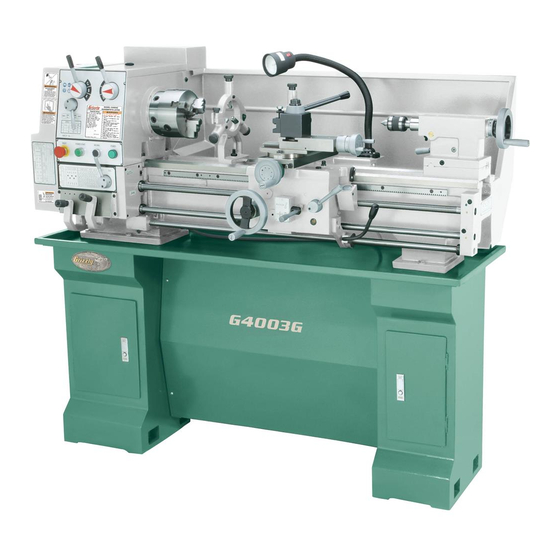
identification figure 1. Model g4003g identification. a. Quick Change gearbox levers Q. Compound rest handwheel b. feed rod lever r. tailstock spindle and Center c. Emergency stop/rEsEt Button s. tailstock spindle lock lever d. poWEr stArt Button tailstock spindle handwheel e. -
Page 6: Machine Data Sheet
machine data sheet Customer Service #: (570) 546-9663 · To Order Call: (800) 523-4777 · Fax #: (800) 438-5901 Product Dimensions: Weight................................1213 lbs. Width (side-to-side) x Depth (front-to-back) x Height..............61 x 26 x 54-1/2 in. Footprint (Length x Width)....................... 57-1/2 x 14-1/2 in. Shipping Dimensions: Carton #1 Type.............................. - Page 7 Main Specifications: Operation Info Swing Over Bed............................12 in. Distance Between Centers........................36 in. Swing Over Cross Slide..........................7 in. Swing Over Saddle.......................... 11-11/32 in. Swing Over Gap............................17 in. Maximum Tool Bit Size..........................5/8 in. Compound Travel..........................3-1/4 in. Carriage Travel............................
- Page 8 Other Kilowatt Output............................1.119 Other Specifications: Country Of Origin ............................... China Warranty ................................1 Year Serial Number Location ......................ID Label on Headstock Assembly Time ............................1-1/2 hours Features: Removable Gap Bed Allows Turnings up to 17" in Diameter Easy to Use Lever Controls Full Length Splash Guard On/Off Reverse Switch on Carriage Halogen Work Light...
-
Page 9: Section 1: Safety
section 1: safety For Your Own Safety, Read Instruction Manual Before Operating this Machine The purpose of safety symbols is to attract your attention to possible hazardous conditions. This manual uses a series of symbols and signal words intended to convey the level of impor- tance of the safety messages. - Page 10 DISCONNECTING POWER SUPPLY. FORCING MACHINERY. GUARDS & COVERS. APPROVED OPERATION. NEVER STAND ON MACHINE. STABLE MACHINE. DANGEROUS ENVIRONMENTS. AWKWARD POSITIONS. ONLY USE AS INTENDED. USE RECOMMENDED ACCESSORIES. UNATTENDED OPERATION. CHILDREN & BYSTANDERS. MAINTAIN WITH CARE. REMOVE ADJUSTING TOOLS. CHECK DAMAGED PARTS. SECURING WORKPIECE.
-
Page 11: Additional Safety Instructions For Lathes
additional safety instructions for lathes understanding the machine. read preventing a cutting tool/chucK crash. Always release automatic feeds after and understand this manual before operating machine. completing a job. cleaning machine. to avoid entanglement avoiding startup inJuries. Make sure and lacerations, do not clear chips by hand. use workpiece, cutting tool, and tool post have a brush, and never clear chips while the lathe is adequate clearance before starting lathe. -
Page 12: Glossary Of Terms
Become familiar with these terms for assembling, adjusting or operating this machine. your safety is very important to us at grizzly! arbor: A machine shaft that supports a cutting headstock: the major lathe component that tool. -
Page 13: Section 2: Power Supply
section 2: poWer supply availability Serious injury could occur if you connect the machine to power before completing the setup process. DO NOT connect to power until instructed later in this manual. circuit requirements for 220v nominal voltage ......220v/240v cycle ............60 hz Electrocution, fire,... -
Page 14: Grounding Instructions
grounding instructions Serious injury could occur if you connect the machine to power before completing the setup process. DO NOT connect to power until instructed later in this manual. GROUNDED 6-15 RECEPTACLE 6-15 PLUG extension cords figure 2. typical 6-15 plug and receptacle. No adapter should be used with the required plug. -
Page 15: Section 3: Setup
section 3: setup items needed for setup this machine presents serious injury hazards to untrained users. read through this entire manu- the following items are needed to complete the al to become familiar with setup process, but are not included with your the controls and opera- machine: tions before starting the... -
Page 16: Hardware Recognition Chart
hardware recognition chart -14- Model g4003g (Mfg. since 4/08) -
Page 17: Inventory
inventory X. drill Chuck B16 1.5-13mm ......1 drill Chuck Key ........... 1 z. spider screws ..........4 aa. Cabinet Base fasteners: —hex Bolts M12-1.75 x 40 ......6 —flat Washers 12mm ........ 6 —phillips head screws M6-1 x 10 ... 12 —hex nuts M6-1 ........ -
Page 18: Site Considerations
site considerations Weight Load Physical Environment Machine Data Sheet Space Allocation Electrical Installation See below for required space allocation. Lighting Children or untrained people may be seriously injured by this machine. Only install in an access restricted location. figure 5. Minimum wall clearances. -16- Model g4003g (Mfg. -
Page 19: Cleanup
cleanup Gasoline or products with low flash points can explode or cause fire if used to clean machin- ery. Avoid cleaning with these products. Many cleaning solvents are toxic if concentrat- ed amounts are inhaled. Only work in a well-venti- lated area. -
Page 20: Securing To Floor
securing to floor cabinet base assembly We recommend that you secure your lathe to the floor. Because floor materials may vary, floor mounting hardware is not included. since this is refer to the base parts breakdown on page 65 a precision machine, it is important to level the for a detailed illustration and parts identification machine with a precision level when mounting. -
Page 21: Lifting & Moving
lifting & moving Move the apron toward the right to help bal- ance the load, as shown in figure 8. position the chip pan on top of the base assembly so that the six lathe mounting holes align with top holes of the cabinets. un-bolt the lathe from the pallet. -
Page 22: Power Connection
power connection test run & break-in Before the machine can be connected to the NOTICE power source, an electrical circuit, power cord, plug, and receptacle must be prepared according never shift lathe gears when lathe is to the poWer supply section in this manual, operating, and make sure both the half-nut and all previous setup instructions in this manual lever and the feed lever are disengaged... -
Page 23: Tailstock Setup
tailstock setup the tailstock alignment was set at the factory with the headstock. however, we recommend that you take the time to ensure that the tailstock is aligned to your own desired tolerances. speed levers to align the tailstock: Center drill a 6'' long piece of bar stock on both ends. - Page 24 Attach a lathe dog to the bar stock from — if the stock is thinner at the tailstock end, step 1 and mount it between the centers (as the tailstock needs to be moved away from shown in figure 14). the operator by at least the amount of the taper (figure 16).
-
Page 25: Section 4: Operation
600 rpM, move the alpha lever until the indicator arrow points to c. -
Page 26: Mounting Chuck And Faceplate
mounting chuck and to remove a chuck: faceplate disConnECt lAthE froM poWEr! place a piece of plywood across the lathe ways and position it just under the chuck. the Model g4003g is shipped with the 3-jaw the board should be at least 8" wide and 10" chuck installed. - Page 27 to install a chuck: turn the other cams in the same way. Make sure to support the chuck with one hand as you align the last cam. the chuck may come disConnECt lAthE froM poWEr! off at this point, so it is important you are ready to support its weight.
-
Page 28: Centers
centers spider A tailstock center supports stock that is too your lathe is equipped with a set of outboard long to be supported by the chuck alone. the spindle supports otherwise known as a "spi- der" (figure 23). use the spider when a long tailstock barrel and live center have an Mt#3 taper. -
Page 29: Steady Rest
steady rest follow rest the steady rest supports long, small diameter the follow rest is normally used with small diam- stock that otherwise could not be turned because eter stock to prevent the workpiece from “spring- of deflection. ing” under pressure from the turning tool. We replaced the common brass wear pads at We replaced the common brass wear pads at the ends of the fingers with bearings. -
Page 30: Feed Direction Lever
feed direction lever feed rod lever NOTICE NOTICE never move levers while the lathe is run- never move levers while the lathe is run- ning, and never force any lever when shift- ning, and never force any lever when shift- ing. -
Page 31: Gearbox Levers
gearbox levers feed rate chart the far left column in the feed rate chart (figure NOTICE 29) shows which change gears must be installed so the chart will be accurate. never move levers while the lathe is run- ning, and never force any lever when shift- to make a longitudinal cut in inches, use the ing. -
Page 32: Carriage/Cross Feed Lever
carriage/cross feed half-nut lever and lever inch threading longitudinal and cross slide powered motions are the half-nut lever clamps and releases the half- controlled by the carriage/cross feed lever. the nut, which clamps around the leadscrew (figure 31). the lever is only engaged while cutting lever pivots through two stops that require moving the lever left and right as well as up and down. - Page 33 When the half-nut lever is engaged, the dial stops While other thread pitches may be achieved, the turning. By carefully engaging the half-nut as the g4003g is designed so that no gear changes are appropriate line or number passes by the indicator needed for cutting inch threads.
-
Page 34: Change Gears And Metric Threading
change gears and the chart is divided into 3 main columns. starting from the left: gear diagram, Combination of gears metric threading per pitch. to use the chart: this lathe can cut 29 different metric threads, but find the desired pitch in the chart (figure gear changes are required to cut all of the listed 35) . -
Page 35: Carriage Handwheels
loosen the 17mm arm-support hex nut and 50 tooth change gear meshes with the 91 tooth rotate the bracket so the middle gear moves middle gear and the 60 tooth change gear mesh- away from gear f (figure 36). es with the 86 tooth middle gear. Begin threading, but remember you cannot use the thread dial for the metric threads. -
Page 36: Tool Post & Holder
tool post & holder tailstock controls figure 38 shows tool post and a holder with the tailstock (figure 39) serves many functions. optional bit. Cutting tools can be secured and the primary use is for holding centers and drill removed by tightening or loosening the clamping chucks. -
Page 37: Section 5: Accessories
“this is good stuff! i use it on my lathes figure 43. Cleaner/degreaser available from at home.” grizzly. S. Balolia – President of Grizzly Industrial figure 41. primrose Armor plate lubricant. -35- Model g4003g (Mfg. since 4/08) -
Page 38: Section 6: Maintenance
section 6: maintenance basic maintenance check for the following conditions and repair or replace when necessary: • loose mounting bolts and chuck. • Worn switch or safety features. • Worn or damaged cords or plug. • Any other condition that could hamper the safe operation of this machine. - Page 39 Quick Change Gearbox, see Figure 46 Tailstock , see Figure 48 lubrication for the gearbox is provided through the tailstock is fitted with three oiling ports. the two oil points, labeled "oil nipple." Add a squirt or tailstock barrel may be oiled directly. Apply oil two of oil after every three-to-four hours of use.
-
Page 40: Section 7: Service
section 7: service troubleshooting review the troubleshooting and procedures in this section to fix your machine if a problem develops. if you need replacement parts or you are unsure of your repair skills, then feel free to call our technical support at (570) 546-9663. motor &... - Page 41 troubleshooting operation and Work results symptom possible Cause possible solution Entire machine 1. Workpiece is unbalanced. 1. reinstall workpiece so it is as centered with the spindle bore as possible. vibrates excessively upon 2. Worn or broken gear present. 2. inspect gears and replace if necessary. startup and while 3.
-
Page 42: Gibs
gibs there are three main gib adjustments for the Model g4003g. they are: the cross-slide gib, the compound slide gib and the saddle gib. Cross-slide Gib, see Figure 49 the gib on the cross-slide is adjusted by the two screws located at each end. to adjust, loosen the set screw set screw located along the edge of the cross-slide. -
Page 43: Bearing Preload
bearing preload Saddle Gib and Saddle Lock, see Figure 51 the saddle is supplied with a square head bolt on the front right hand side of the slide. this bolt is used to lock the saddle in place for increased this lathe is shipped from the factory with the rigidity when making face cuts. - Page 44 place the chuck key in the cam-lock socket place a dial indicator on the cross slide and and keep the spindle from rotating. move the carriage toward the headstock until the contact point of the indicator touches the spindle face (figure 56). using a spanner wrench, or hammer-and- punch, loosen the outer spanner lock nut (figure 54) counterclockwise and remove it.
- Page 45 to confirm that the bearings are correctly pre- since it can take great effort to turn the inner loaded: spanner nut, you may find it difficult to know if you have gone past the zero end-play point or not. you may find it easiest to have some- Make sure all safety precautions have been one watch the dial for you while you tighten taken and setup steps are complete to make...
-
Page 46: Section 8: Wiring
WIRE/COMPONENT DAMAGE. MOTOR WIRING. MODIFICATIONS. CAPACITORS/INVERTERS. WIRE CONNECTIONS. CIRCUIT REQUIREMENTS. EXPERIENCING DIFFICULTIES. The photos and diagrams included in this section are best viewed in color. You can view these pages in color at www.grizzly.com. -44- Model g4003g (Mfg. since 4/08) -
Page 47: Wiring-Electrical Box
Wiring—electrical box figure 59. Electrical box wiring. READ ELECTRICAL SAFETY -45- Model g4003g (Mfg. since 4/08) ON PAGE 44! - Page 48 READ ELECTRICAL SAFETY -46- Model g4003g (Mfg. since 4/08) ON PAGE 44!
-
Page 49: Wiring -Motor & Control Panel
Wiring —motor & control panel figure 60. Motor wiring. figure 61. Control panel wiring. READ ELECTRICAL SAFETY -47- Model g4003g (Mfg. since 4/08) ON PAGE 44! - Page 50 READ ELECTRICAL SAFETY -48- Model g4003g (Mfg. since 4/08) ON PAGE 44!
-
Page 51: Wiring -Plug, Light & Spindle Switch
Wiring —plug, light & spindle switch figure 62. Work light wiring. figure 63. spindle on/off switch. READ ELECTRICAL SAFETY -49- Model g4003g (Mfg. since 4/08) ON PAGE 44! - Page 52 READ ELECTRICAL SAFETY -50- Model g4003g (Mfg. since 4/08) ON PAGE 44!
-
Page 53: Section 9: Parts
section 9: parts components REF PART # DESCRIPTION REF PART # DESCRIPTION P4003G0001 4-JAW UNIVERSAL CHUCK 8" P4003G0024 CARBIDE TIP DEAD CENTER MT#3 P4003G0002 FACEPLATE 10" P4003G0025 STANDARD DEAD CENTER MT#3 P4003G0003 OIL BOTTLE P4003G0026 ARBOR B16-MT#3 P4003G0004 TOOL BOX P4003G0027 DEAD CENTER SPINDLE SLEEVE P4003G0005... -
Page 54: Gearbox Gearing
gearbox gearing -52- Model g4003g (Mfg. since 4/08) - Page 55 gearbox gearing parts list REF PART # DESCRIPTION REF PART # DESCRIPTION PR56M EXT RETAINING RING 45MM 138-1 P4003G0138-1 CAM LOCK P4003G0102 GEAR 36T P4003G0139 KEY 8 X 8 X 80 P4003G0103 GEAR 55T PK43M KEY 8 X 8 X 45 PK14M KEY 5 X 5 X 18 PSB80M...
-
Page 56: Gearbox Shifters
gearbox shifters -54- Model g4003g (Mfg. since 4/08) - Page 57 gearbox shifters parts list PART # DESCRIPTION PART # DESCRIPTION PN02M HEX NUT M10-1.5 P4003G0211 SHAFT P4003G0175 OIL PLUG P4003G0212 GEAR 40T P4003G0176 COVER PK12M KEY 5 X 5 X 30 PSB06M CAP SCREW M6-1 X 25 1100 PSB77M CAP SCREW M12-1.75 X 30 P4003G0178 GASKET 1101...
-
Page 58: Quick Change System
Quick change system -56- Model g4003g (Mfg. since 4/08) - Page 59 Quick change system parts list REF PART # DESCRIPTION REF PART # DESCRIPTION P4003G0301 LEAD SCREW P4003G0341 GEAR 16T PRP10M ROLL PIN 5 X 36 P4003G0342 GEAR 32T P8103 THRUST BEARING 8103 P4003G0343 GEAR 16T P4003G0305 SHAFT P4003G0344 GEAR 16T PK19M KEY 5 X 5 X 14 P4003G0345...
-
Page 60: Apron
apron -58- Model g4003g (Mfg. since 4/08) -
Page 61: Apron Parts List
apron parts list REF PART # DESCRIPTION REF PART # DESCRIPTION P4003G0401 HANDLE PW03M FLAT WASHER 6MM P4003G0402 HANDWHEEL PSB29M CAP SCREW M6-1 X 40 P4003G0403 GRADUATED DIAL P4003G0436 SHAFT PRP28M ROLL PIN 5 X 40 P4003G0437 SAFETY SHIFTER PSS25M SET SCREW M6-1 X 20 PSS17M SET SCREW M8-1.25 X 6... -
Page 62: Saddle
saddle -60- Model g4003g (Mfg. since 4/08) -
Page 63: Saddle Parts List
saddle parts list REF PART # DESCRIPTION REF PART # DESCRIPTION P4003G0501 SADDLE PS57M PHLP HD SCR M5-.8 X 14 PS59M PHLP HD SCR M3-.5 X 14 P4003G0522 SLIDE PLATE P4003G0503 WIPER P4003G0523 SLIDE PLATE PS24 PHLP HD SCR 8-32 x 3/8 P4003G0524 SLIDE PLATE P4003G0505... -
Page 64: Compound Slide
Compound Slide REF PART # DESCRIPTION REF PART # DESCRIPTION P4003G0601 GIB SCREW P8101 THRUST BEARING 8101 P4003G0602 P4003G0614 GRADUATED DIAL P4003G0603 COMPOUND SLIDE P4003G0615 SPANNER NUT PN03M HEX NUT M8-1.25 P4003G0616 BRACKET P4003G0605 COMPOUND REST MOUNTING BOLT P4003G0617 HANDLE LARGE P4003G0606 COMPOUND REST MOUNTING BOLT 617A P4003G0617A HANDLE SMALL... -
Page 65: Tailstock
tailstock REF PART # DESCRIPTION REF PART # DESCRIPTION PK136M KEY 8 X 8 X 30 P4003G0717 LOCK SCREW P4003G0703 QUILL P4003G0718 LOCK SHAFT P4003G0704 TAILSTOCK P4003G0719 HANDLE P4003G0705 BASE P4003G0720 SHAFT PSS39M SET SCREW M10-1.5 X 50 PRP05M ROLL PIN 5 X 30 P4003G0707 SPECIAL SCREW P4003G0722... -
Page 66: Lathe Bed & Motor
lath bed & motor breakdown lathe bed & motor -64- Model g4003g (Mfg. since 4/08) -
Page 67: Base
base breakdown base -65- Model g4003g (Mfg. since 4/08) - Page 68 lathe bed, motor & base parts list REF PART # DESCRIPTION REF PART # DESCRIPTION PVA32 V-BELT A-32 4L320 PSB70M CAP SCREW M10-1.5 X 45 PSS05M SET SCREW M5-.8 X 10 P4003G0817 THREADED TAPER PIN P4003G0803 HEAD KEY PS68M PHLP HD SCR M6-1 X 10 PW04M FLAT WASHER 10MM PW03M...
-
Page 69: Feed Rod
feed rod feed rod parts list REF PART # DESCRIPTION REF PART # DESCRIPTION P4003G0901 BRACKET P4003G0911 HANDLE PSB25M CAP SCREW M6-1 X 11 P4003G0912 BRACKET P4003G0903 OIL CAP PSB27M CAP SCREW M6-1 X 14 PRP34M ROLL PIN 6 X 55 PRP49M ROLL PIN 5 X 25 PSS02M... -
Page 70: Machine Labels
(800) 523-4777 or www.grizzly.com to order new labels. -68-... -
Page 71: Electrical Components
electrical components PART # DESCRIPTION PART # DESCRIPTION 1201 P4003G1201 TRANSFORMER 1208 P4003G1208 TERMINAL BLOCK 12-POLE 1202 P4003G1202 FUSE HOLDER 2A 1209 P4003G1209 TERMINAL BLOCK 20-POLE 1202-1 P4003G1202-1 2 AMP FUSE 1210 P4003G1210 STOP RESET BUTTON 1203V2 P4003G1203V2 FUSE HOLDER 5A V2.10.06 1211 P4003G1211 POWER ON BUTTON... -
Page 72: Steady & Follow Rest Assemblies
steady & follow rest assemblies PART # DESCRIPTION PART # DESCRIPTION 1300 P4003G1300 COMPLETE STEADY REST ASSY 1315 PW06M FLAT WASHER 12MM 1301 P4003G1301 HANDLE 1316 P4003G1316 CLAMP PLATE 1302 PSS02M SET SCREW M6-1 X 6 1317 PB43M HEX BOLT M12-1.75 X 75 1303 P4003G1303 BUSHING... -
Page 73: Warranty Card
WARRANTY CARD The following information is given on a voluntary basis. It will be used for marketing purposes to help us develop better products and services. Of course, all information is strictly confidential. Note: We never use names more than 3 times. _____________________________________________________________________ _________________________________________________________________________________ _________________________________________________________________________________... -
Page 75: Warranty And Returns
Warranty and returns -73- Model g4003g (Mfg. since 4/08) - Page 76 Buy Direct and Save with Grizzly – Trusted, Proven and a Great Value! ® ~Since 1983~ Visit Our Website Today For Current Specials! ORDER 24 HOURS A DAY! 1-800-523-4777...