Table of Contents
Advertisement
Advertisement
Table of Contents

Related Manuals for Toro Power Max


Summary of Contents for Toro Power Max
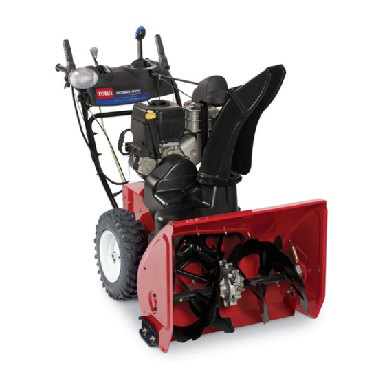
- Page 1 Consumer Products Power Max™ Snowthrower Service Manual...
- Page 2 THIS PAGE INTENTIONALLY LEFT BLANK...
- Page 3 For information specifi c to the engines used on this unit, refer to the engine chapter of this book. Power Max model years 2004 - 2005 are covered in this manual. The manual may also be specifi ed for use on later model products.
-
Page 4: Table Of Contents
Traction Cable Adjustment ....4 - 11 Replace & Adjust Wheel Clutch Cables ....4 - 11 Power Max Service Manual... - Page 5 Disassembly ......9 - 1 Drive System Reassembly ..... 9 - 9 Power Max Service Manual...
- Page 6 Tires ....... . 12 - 1 Power Max Service Manual...
-
Page 7: Safety Information
Bloomington, MN 55420 This manual is intended as a service and repair manual only. The safety instructions provided herein are for troubleshooting, service, and repair of the Power Max™ snowthrower. The Power Max™ snowthrower operator’s Think Safety First Avoid unexpected starting of engine... - Page 8 THIS PAGE INTENTIONALLY LEFT BLANK Power Max Service Manual...
-
Page 9: Specifi Cations
Unleaded regular grade gasoline mixed at a ratio of 50:1 2.6 oz. (80ml) oil / 1 US gallon (3.8l) gasoline. 2-cycle Required oil Toro 2 cycle oil or any 2-cycle oil that is NMMA TCW3 (ISO E GD) certifi ed as an acceptable substitute. 4-cycle Fuel Unleaded regular grade gasoline (do not mix with oil). - Page 10 3. The full length of the auger shaft before installing the augers. 4. The outer 5” (12.7cm) of the axle before installing the wheels. Accessories • Drift Breaker • Tire Chains • Snow Cab • Weight Kit (Required with Cab) Power Max Service Manual...
-
Page 11: Torque Specifi Cations
Fastener Identification Recommended fastener torque values are listed in the following tables. For critical applications, as determined by Toro, either the recommended torque or a torque that is unique to the application is clearly identified and specified in the service manual. - Page 12 Note: Torque values may have to be reduced when installing fasteners into threaded aluminum or brass. The specific torque value should be determined based on the fastener size, the aluminum or base material strength, length of thread engagement, etc. Power Max Service Manual...
- Page 13 Note: Torque values may have to be reduced when installing fasteners into threaded aluminum or brass. The specific torque value should be determined based on the fastener size, the aluminum or base material strength, length of thread engagement, etc. Power Max Service Manual...
- Page 14 200 ± 100 in-lb torque values. All torque values are based on non- lubricated fasteners. Conversion Factors in-lb X 11.2985 - N-cm N-cm X - 0.08851 = in-lb ft-lb X 1.3558 = N-m N-cm X 0.73776 - ft-lb Power Max Service Manual...
- Page 15 11.112 15/16 0.9375 23.812 29/64 0.453125 11.509 61/64 0.953125 24.209 15/32 0.46875 11.906 31/32 0.96875 24.606 31/64 0.484375 12.303 63/64 0.984375 25.003 0.5000 12.700 1.000 25.400 1 mm = 0.03937 in. 0.001 in. = 0.0254 mm Power Max Service Manual...
- Page 16 Kilopascal 6.895 Pressure Foot-pounds Newton-Meters 1.356 Foot-pounds Kilogram-Meters Work 0.1383 Inch-pounds Kilogram-Centimeters 1.152144 Quarts Liters 0.9463 Liquid Volume Gallons Liters 3.785 Gallons/Minute Liters/Minute 3.785 Liquid Flows Fahrenheit Celsius 1. Subtract 32° Temperature 2. Multiply by 5/9 Power Max Service Manual...
-
Page 17: Engine
900 North Street Grafton, WI 53024 Phone 262-377-2700 2-Cycle Engine All 2-cycle models use the Toro R tek engine. Service is handled through the Toro system. Detailed engine repair information is available in the “E” Engine Service Fig 003 MVC-001X Manual, Form No. -
Page 18: Primer Button
Switch troubleshooting is provided in the atmospheric vent for the carburetor bowl. If the line electrical section. is kinked or the vent hole in the bulb is plugged, the carburetor may fl ood. Fig 006 MVC-863XA Power Max Service Manual... -
Page 19: Fuel Tank, Fuel Line, Fuel Filter
fi lter are properly installed. The primer line connects to the back side of the primer then is routed over the fuel line, over the foam block (Fig. 008). Fig 008 MVC-865XA Power Max Service Manual... - Page 20 (Fig. 010). Then rotate the shroud clockwise into place. Fig 010 MVC-893XC 3. While the engine shroud is still loose, install both belt covers. Then install and secure the front and rear engine covers to each other and to the chassis. Power Max Service Manual...
-
Page 21: Controls
1. To remove the Quick Stick, unhook the Z bend and gear and causes the chute to pivot side to side. disconnect the defl ector cable from the underside of the Quick Stick (Fig. 014). Fig 012 MVC-039F Fig 014 MVC-870XA Power Max Service Manual... - Page 22 Quick Stick out of the control latch tabs on the rear. Set the cover aside (Fig. 016). panel. Note the location of the cable clamp, as it is necessary for latch cable function (Fig. 018). Fig 016 MVC-902X Fig 018 MVC-725F Power Max Service Manual...
-
Page 23: Disassembly
2. Remove the two screws on the right hand side of the screws and lift off the top handle half (Fig. 022). chute control cover (the part that looks like a ball). Remove both halves and set aside (Fig. 020). Fig 022 MVC-8335X Fig 020 MVC-547F Power Max Service Manual... -
Page 24: Reassembly
While holding the trigger lever in place, rotate the hooked end of the spring until it hooks under the front edge of the trigger lever as shown (Fig. 026). Fig 024 MVC-554F Fig 026 MVC-758F A. Latch trigger Power Max Service Manual... -
Page 25: Installation
MVC-171X (Fig. 027). 2. Remove the Shoulder Screw under the left handgrip (Fig. 029). When it is removed the Lockout Latch, Torsion Spring, Flat Washer, and Locknut will drop out. Fig 027 MVC-872X Fig 029 MVC-167X Power Max Service Manual... - Page 26 Fig 031 MVC-170X Fig 033 MVC-174X Note: Steps 1 and 2 above do not need to be done in that order. In fact you can remove the rod without removing the shoulder bolt and vice versa. Power Max Service Manual...
-
Page 27: Control Operation, Replacement & Adjustment
(Fig. 034). Fig 035 MVC-870X Fig 034 MVC-176X 2. Remove the cable clamp and disconnect the cable end from the defl ector. Reverse this process to install a new cable (Fig. 036). Fig 036 MVC-882X Power Max Service Manual... -
Page 28: Defl Ector Cable Adjustment
fi rst friction wheel in the traction drive by a shift rod. Moving gear. the shift lever moves the friction wheel to change wheel direction and speed (Fig. 038). Fig 040 MVC-560F Fig 038 MVC-901XA Power Max Service Manual... -
Page 29: Auger Control
(Fig. 044). The idler pulley is initially installed in the outer hole. If necessary, the idler can be moved to achieve the correct tension. 2004 models have only one hole in the idler. Fig 042 MVC-901XA Fig 044 MVC-016X Power Max Service Manual... -
Page 30: Auger Brake Adjustment
2. Remove the belt cover and check the gap between the welded washer/nut assembly and the brake arm tab. The gap should be .100” (2.5mm) Fig 047 MVC-899XA 4-10 Power Max Service Manual... -
Page 31: Traction Cable Adjustment
(maximum 1/16” [1.5mm]). Secure the jam nut on the turnbuckle (Fig. 049). The left hand belt cover has been removed only for clarity. Fig 050 MVC-892X Power Max Service Manual 4-11... - Page 32 fi tting (Fig. 052). The cable fi tting lower end of the cable into the shift collar outside in, can then be pushed out of the shift plate. as shown (Fig. 054). Fig 052 MVC-899X Fig 054 MVC-878XYZ1 4-12 Power Max Service Manual...
- Page 33 (6mm). If it is greater, loosen the cable clamp nut, slide the cable jacket up slightly, tighten the cable clamp nut, and check the gap again. Repeat steps for other cable (Fig. 057). Fig 057 MVC-891XLY Power Max Service Manual 4-13...
- Page 34 THIS PAGE INTENTIONALLY LEFT BLANK 4-14 Power Max Service Manual...
-
Page 35: Belt Replacement
4. The brake assembly can be lifted out of the chassis (Fig. 061). 2. Remove the belt guide. Be careful to avoid bending the guide (Fig. 059). Fig 061 MVC-067X A. Brake Assembly Fig 059 MVC-007F Power Max Service Manual... -
Page 36: Traction Belt
2. On the left side of the machine, remove the hairpin cotter from the speed control link (Fig. 065). Fig 063 MVC-886XB Reverse the process to install a new belt. Use Loctite 242 and torque the engine pulley to 29 ft-lbs. (39.3 Nm) Fig 065 MVC-897X Power Max Service Manual... -
Page 37: Belt Adjustment
Engage the auger belt and look between the belt and belt guide on the left side. There should be about 1/8” (3.2mm) gap (Fig. 067). Tighten the belt guide mounting bolts. Fig 067 MVC-822X Power Max Service Manual... - Page 38 THIS PAGE INTENTIONALLY LEFT BLANK Power Max Service Manual...
-
Page 39: Auger Housing
AUGER HOUSING AUGER HOUSING COMPONENTS SCRAPER The Power Max snow throwers are offered in two widths: The scraper is a replaceable surface attached to the 26” and 28” (66cm and 71cm). The augers, auger shaft, leading edge of the auger housing. It is a wear part and... -
Page 40: Adjusting The Skids And Scraper - Fixed
Important: If the machine is to be used on rough, broken or uneven pavement, adjust the skids to raise the scraper. For gravel surfaces, adjust the skids further down to prevent the snowthrower from picking up rocks. Power Max Service Manual... -
Page 41: Adjusting The Skids And Scraper - Pivoting
6. Check to ensure the rotating part of the auger does not touch the ground. This can damage the auger as well as the pavement. Power Max Service Manual... - Page 42 THIS PAGE INTENTIONALLY LEFT BLANK Power Max Service Manual...
-
Page 43: Auger Gearbox
If the front engine cover is loose it will make removing the belt cover much easier (Fig. 072). Fig 073 MVC-006XB Fig 072 MVC-000 Fig 074 MVC-005X Power Max Service Manual... - Page 44 (Fig. 075). Be careful to avoid bending the guide. Fig 077 MVC-008X Fig 075 MVC-007F 6. Remove the auger brake assembly (Fig. 078). 4. Remove 2 capscrews for the auger brake assembly (Fig. 076). Fig 078 MVC-067X Fig 076 MVC-1883X Power Max Service Manual...
- Page 45 8. Loosen the 2 set screws on the auger pulley. A long 10. Disconnect the spring on both ends of the pivoting extension and a ratchet will be necessary scraper (Fig. 082). (Fig. 080). Fig 082 MVC-787F Fig 080 MVC-003F Power Max Service Manual...
-
Page 46: Secondary Method
2. Remove the cover over the chute gears. Free the chute latch cable from its clamp and disconnect the chute latch cable (Fig. 085). Fig 083 MVC-900XA 14. The auger gearbox is now ready for disassembly and repair. Fig 085 MVC-774X Power Max Service Manual... -
Page 47: Gearbox Installation
There should be no more than 1/8” (3mm) front to back movement in the shaft. Fig 087 MVC-1135X 6. Once separated, the auger pulley is in the open. Once the pulley and key have been removed, perform the preceding steps 12-14 to complete auger removal. Power Max Service Manual... -
Page 48: Auger Gearbox Repair
3. Even if you have drained the oil, we recommend supporting the gearbox over a drain pan when you separate the case halves. Remove the screws and separate the case halves. Power Max Service Manual... -
Page 49: Failure Analysis
The bushing next to the ring defl ects most of the oil that is thrown towards that area. The loose fi t provides a vent for the case (Fig. 091). Fig 091 DSC-0061 Power Max Service Manual... -
Page 50: Gearbox Assembly
(Fig. 093). This will allow space for the seal on the outside. Wipe up any Loctite that is visible. The Loctite must not get into the gear or seal area. Fig 093 MVC-710X Power Max Service Manual... - Page 51 Apply a thin coat of thrust bearing, thrust washer, bushing and seal. Hylomar (Toro PN 505-129) to both halves. Allow There is also a bushing on the worm end of the seal it to cure until it is dull and tacky, at least one hour.
- Page 52 THIS PAGE INTENTIONALLY LEFT BLANK 7-10 Power Max Service Manual...
-
Page 53: Non-Wheel Clutch Traction Drive System
Moving the wheel from side to side will change direction of rotation and the farther out from center the wheel contacts the plate, the faster the speed. Power Max Service Manual... - Page 54 (Fig. 102). Fig 100 MVC-9012X.jpg A. Upper Cover C. Bottom Pan B. Lower Cover Fig 102 MVC-771X.jpg 3. Remove the screw securing each end of the sprocket shaft (Fig. 101). A. Thrust Washer Fig 101 MVC-9022X.jpg Power Max Service Manual...
- Page 55 9. Remove the two screws securing the shift bracket to Withdraw the axle and remove the thrust washers, the frame (Fig. 106). bearings, gear and key. Fig 106 MVC-1001X.jpg Fig 104 MVC-1904X.jpg A. Axle Bearing Power Max Service Manual...
- Page 56 12. Slip the traction idler off the traction belt. This can be done from either the top or the bottom. The traction idler will rotate to this position (Fig. 109). Fig 109 MVC-1003X.jpg A. Traction Idler Power Max Service Manual...
- Page 57 14. Reach up to the far left corner of the pulley pivot loosen the nut (Fig. 113). assembly and unhook the spring from the pivot assembly (Fig. 111). Fig 113 MVC-870XB.jpg Fig 111 MVC-1005X.jpg A. Spring B. Pivot Assembly Power Max Service Manual...
-
Page 58: Reassembly
170 - 300 in-lbs. (196 - 345kg/com). 3. Lubrication A. Light coat of engine oil to intermediate shaft. B. Apply light coat of anti-seize to outer 5” of axle shaft (circumference of 44 tooth axle gear). Power Max Service Manual... -
Page 59: Wheel Clutch Traction Drive System
11 tooth pinion gear from the 32 tooth gear. Fig 116 MVC-892XB.jpg DISASSEMBLY 3. Remove bottom plate (Fig. 117). 1. Disconnect shift linkage and remove tires (Fig 115). Fig 117 MVC-893XB.jpg Fig 115 MVC-889X.jpg Power Max Service Manual... - Page 60 Z bend of the cable end out of the upper clutch collar (Fig. 121). 5. Remove both bolts that hold the wheel clutch assembly to the housing (Fig. 119). Fig 121 MVC-898XB.jpg Fig 119 MVC-895X.jpg Power Max Service Manual...
- Page 61 Note: Install a screw and washer into each end of the shaft to keep the parts from sliding off (Fig. 125). Fig 123 MVC-894XYX.jpg Fig 125 MVC-901XB.jpg To continue with disassembly of the clutch mechanism, go to page xx. Power Max Service Manual...
- Page 62 44-tooth gear inward towards the center of the shaft to expose the woodruff key. Pry up on the outside edge of the key to remove it (Fig. 127). Fig 129 MVC-859XYZ.jpg Fig 127 MVC-856X.jpg Power Max Service Manual...
- Page 63 (Fig. 133). 15. Remove the two screws from the shift rod bracket and remove the traction control lever and bracket assembly from the friction wheel (Fig. 131 and 132). Fig 133 MVC-864XYZ.jpg Fig 131 MVC-859X.jpg Power Max Service Manual...
- Page 64 18. Remove friction wheel from hex shaft by removing 20. Remove extension cover (Fig. 137). the 3 nuts and bolts that hold the friction wheel to the plate on the hex shaft (Fig. 135). Fig 137 MVC-862X.jpg Fig 135 MVC-858X2.jpg Power Max Service Manual...
- Page 65 (Fig. 138). assembly (Fig. 140). Fig 138 Fig 140 MVC-863XB.jpg MVC-865XB.jpg 22. Remove extension spring from housing (Fig. 139). 24. Turn the snowthrower back onto the auger housing. Fig 139 MVC-864X.jpg Power Max Service Manual...
- Page 66 (Fig. pulley plate shaft (Fig. 142). 143). Fig 141 Fig 143 MVC-866XB.jpg MVC-868X.jpg 27. Remove the pivot pulley plate assembly from the housing (Fig. 144). Fig 142 MVC-866Xny.jpg Fig 144 MVC-869X.jpg Power Max Service Manual...
-
Page 67: Drive System Reassembly
(Fig. 147). Fig 145 MVC-870XB.jpg Fig 147 MVC-036X.jpg A. Idler Pulley 2. Install the two bushings and the two “C” clips onto the pivot plate shaft (Fig. 148). Fig 146 MVC-010X.jpg Fig 148 MVC-037X.jpg Power Max Service Manual... -
Page 68: Wheel Clutch Traction Drive System (Cont.)
4. Install long end of spring to cut out on the pivot plate seize or any other lubricant. (Fig. 150) and the short end of the spring to the frame (Fig. 151). Fig 152 MVC-031XYX.jpg Fig 150 MVC-039X.jpg A. Spring 9-10 Power Max Service Manual... - Page 69 5 inches of both ends of the axle shaft. Also apply a light coat to the inside diameter at both ends of the tube about 4 inches (Fig. 156). Fig 154 MVC-867X.jpg Fig 156 MVC-046X.jpg Power Max Service Manual 9-11...
- Page 70 44-tooth gear sprocket into the tube (Fig. 160). Fig 158 MVC-871XYZ.jpg A. Hub Fig 160 MVC-056X.jpg 9-12 Power Max Service Manual...
- Page 71 11-tooth gear of the wheel clutch with anti- washers and push the hairpin cotter into place (Fig. seize (Fig. 164). 162). Repeat for the other side. Fig 164 MVC-035X.jpg Fig 162 MVC-061X.jpg A. Hairpin Cotter Power Max Service Manual 9-13...
- Page 72 20. Torque the two intermediate shaft screws to 170 to 300 in-lbs. (19.2 to 33.9 Nm) (Fig. 168). A. Left Collar B. Right Collar 18. Route the chains around the 32-tooth gear of the clutch assembly (Fig. 166). Fig 168 MVC-8562X.jpg Fig 166 MVC-2207X.jpg 9-14 Power Max Service Manual...
- Page 73 Fig 169 MVC-032XZV.jpg 23. Install shift rod / traction rod lever onto the housing (Fig. 172) making sure the traction control fi ts into the friction wheel (Fig. 173). Fig 170 MVC-899XB.jpg Fig 172 MVC-859X2.jpg Power Max Service Manual 9-15...
- Page 74 (Fig. 175). Fig 173 MVC-031XYX.jpg Fig 175 MVC-2193X.jpg 24. Install the lower cover (Fig. 174). 26. Connect the shift linkage to the shift rod / traction rod lever (Fig. 176). Fig 174 MVC-872XYY.jpg Fig 176 MVC-874XYY.jpg 9-16 Power Max Service Manual...
-
Page 75: Wheel Clutch Disassembly
2. Slide off washer behind the 11-tooth gear (Fig. 180). Fig 178 MVC-884XT.jpg Fig 180 MVC-877X.jpg 29. Install the belt extension cover and belt cover. 30. Check clutch cable adjustment and adjust if necessary. See Adjustments Power Max Service Manual 9-17... - Page 76 fl ange (A). Note: This hole, for the spring, has been changed to a “D” shape during 2004 for ease in identifying the correct hole (B). Fig 184 MVC-883XWC.jpg Fig 182 MVC-879X.jpg 9-18 Power Max Service Manual...
- Page 77 9. Remove the retainer plate off of the gear hub (Fig. under the pawls and set aside (Fig. 185). 187). Fig 187 MVC-888XWC.jpg Fig 185 MVC-884XB.jpg 8. Remove 6 (per side) T-27 torx screws that hold the pawl supports (Fig. 186). Fig 186 MVC-886X.jpg Power Max Service Manual 9-19...
-
Page 78: Wheel Clutch Reassembly
1. Set the 32-tooth gear on a fl at surface and install pawls. Apply a light coat of oil Toro part no. 505-5 to dowel pins then install dowel pins into the pawl assembly (Fig. 190). - Page 79 6. Torque the screws no more then 50 - 70 in-lbs. (5.65 (11.3 to 14.1 Nm) (Fig. 193). – 7.9 Nm). 7. Slide fl at washers next to guides (Fig. 195). Fig 193 MVC-905XWC.jpg Fig 195 MVC-1911X.jpg Power Max Service Manual 9-21...
- Page 80 (Fig. 197). Fig 198 MVC-001XB.jpg 10. Slide thrust washer onto the 32-tooth sprocket gear Fig 196 MVC-880X.jpg (Fig. 199). Fig 199 MVC-002X.jpg Fig 197 MVC-1915X.jpg 9-22 Power Max Service Manual...
- Page 81 12. Install fl at washer (Fig. 201). 14. Make sure the pawls are up against the thrust washer and the springs are not binding and are compressing properly (Fig. 203). Fig 201 MVC-1177X.jpg Fig 203 MVC-006X.jpg Power Max Service Manual 9-23...
- Page 82 Check each of the 6 pawls to ensure that it returns fully when the shift collar is released. (A non-returning pawl indicates binding or missing parts). Fig 204 MVC-035X.jpg 16. Assembly can now go back into housing (Fig. 205). Fig 205 MVC-1905X.jpg 9-24 Power Max Service Manual...
-
Page 83: Discharge Chute
2. Remove the single screw retaining the gear cover, lift the front of the cover, and slide it to the rear (Fig. 207). Fig 209 MVC-824X Fig 207 MVC-883X Power Max Service Manual 10-1... - Page 84 8. The last chute component is the chute guide. It is secured with three screws (Fig. 211). attached to the auger cover with one screw in front and tabs on the rear (Fig. 213). Fig 211 MVC-804X Fig 213 MVC-891X 10-2 Power Max Service Manual...
- Page 85 Just seating the nut is enough; the nylock feature will keep if from loosening. Fig 214 MVC-893XA The auger cover is attached to the auger housing with carriage bolts and locknuts (Fig. 215). Fig 216 MVC-849X Fig 215 MVC-898XA Power Max Service Manual 10-3...
-
Page 86: Chute Gears
1. To disassemble the chute gears, begin by removing the screw on the chute gear cover (Fig. 217). Fig 218 MVC-144X 3. Remove the locknut and washer from the bottom of the 3 shoulder screws (Fig. 219). Fig 217 MVC-143X Fig 219 MVC-146X 10-4 Power Max Service Manual... - Page 87 7. The chute gear is attached to the bracket by two chute rod (Fig. 221). screws. Remove the screws and lift the gear off the bracket. Note: a plastic spacer is under the bracket. Fig 221 MVC-149X Power Max Service Manual 10-5...
-
Page 88: Assembly
(Fig. 226). Fig 223 MVC-818X 3. Slide the face gear mount on the chute rod, if removed. Slide the face gear on the chute rod (Fig. 224). Fig 226 MVC-828X Fig 224 MVC-161X 10-6 Power Max Service Manual... - Page 89 7. Install the end of the latch cable in the latch and slip the cable under the clamp screw. Pull the cable to the rear until the latch just begins to move and tighten the clamp (Fig. 228). Fig 228 MVC-165X Power Max Service Manual 10-7...
- Page 90 THIS PAGE INTENTIONALLY LEFT BLANK 10-8 Power Max Service Manual...
-
Page 91: Electrical
When the switch is on there should be no continuity. When the switch is off there The light fi xture and the wire harness are Toro parts. The should be continuity between the terminals (Fig. 230). - Page 92 THIS PAGE INTENTIONALLY LEFT BLANK 11-2 Power Max Service Manual...
-
Page 93: Wheels And Tires
On wheel clutch models, the wheel is attached with a bolt and locknut. The traction drive can be declutched by squeezing the levers. This provides the declutching for easy pushing (Fig. 232). Fig 232 MVC-884Xt Power Max Service Manual 12-1... - Page 94 THIS PAGE INTENTIONALLY LEFT BLANK 12-2 Power Max Service Manual...
- Page 95 THIS PAGE INTENTIONALLY LEFT BLANK...
- Page 96 Power Max™ Service Manual Form no. 492-9138...