Sign In
Upload
Manuals
Brands
ge Manuals
Controller
RSTi-EP
ge RSTi-EP Manuals
Manuals and User Guides for ge RSTi-EP. We have
2
ge RSTi-EP manuals available for free PDF download: User Manual, Functional Safety Manual
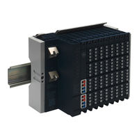
ge RSTi-EP User Manual (425 pages)
standalone 1GHz programmable controller
Brand:
ge
| Category:
Controller
| Size: 11.76 MB
Table of Contents
Table of Contents
5
Document Updates
11
System Overview
12
Double-Click Installation
13
General Description of the Fieldbus Network Adapters
14
General Technical Data for the Fieldbus Network Adapter
15
General Description of I/O Modules
17
Standard Connector
18
HD Connector EP-8360
18
Cable Protection
19
General Technical Data for I/O Modules
20
Mechanical Fixing Elements
21
Type Plate
21
Markers
22
Swivel Marker
22
General Safety Notice
24
Electrostatic Discharge
24
Open Equipment
24
Fusing
25
Earthing (Functional Earth FE)
25
Shielding
25
Overcurrent
25
Intended Use
25
Use in a Potentially Explosive Atmosphere
26
ATEX Zone 2
27
ATEX & Iecex Marking
27
Legal Notice
27
Use of Rsti-EP Stations above 2000M Sea Level
27
Order and Arrangement of the Modules
28
Arrangement of Safe Power-Feed Modules
29
Power Supply Concept
30
Installation Distances
30
Calculation of Space Requirements
32
Use in a Potentially Explosive Atmosphere
32
ATEX & Iecex Marking
33
Spring-Style System Cabling
33
Current Demand and Power Supply
33
Power Supply Derating
33
Example Calculation for the Power Supply
35
Calculation of the Current Demand for the Input Current
35
Calculation of the Current Demand for the Output Current
36
Calculation of Power Loss
38
Calculation of Power Loss for Use in a Potentially Explosive Atmosphere
38
Feedback Energy in Do Modules
38
Calculation of Feedback Energy
39
Parameter Overview
40
Data Width of I/Omodule , Dependent on the Network Adapter Used
51
Profibus Dp Network Adapter Epxpbs001
57
Leds
58
Addressing
60
Connection Diagrams
61
Specifications
62
Supported Modules and Power Supplies
64
Profinet Irt Network Adapter Epxpns001
66
Leds
66
Connection Diagrams
68
Specifications
69
Supported Modules and Power Supplies
70
Ether Cat ® Network Adapter Epxetc001
72
Leds
73
Connection Diagrams
74
Specifications
76
Rsti-EP Status Messages
77
Module Status Messages
78
Module Diagnosis
78
Supported Modules and Power Supplies
79
Modbus ® Tcp Network Adapter Epxmbe001/Epxmbe101
80
Leds
81
Connection Diagrams
83
Specifications
84
Configuration of the IP Address
85
Packed Process Data
89
0X1000 - 0X1006 Network Adapter Identifier
92
0X1000 - 0X1006 Network Adapter Status
92
0X1010 Process Image Length in Bits for the Output Modules
92
0X1010 Process Image Length in Bits for the Input Modules
92
0X1017 Register - Mapping Revision
92
0X1018 - 0X101B Collective Diagnostics Message for I/O Modules
92
0X101C - 0X101F Collective Process Message for I/O Modules
93
0X1028 - 0X102F Module Status
93
0X1030 MODBUS DATA EXCHANGE Watchdog, Current Time
93
0X1120 MODBUS DATA EXCHANGE Watchdog, Predefined Time
93
0X1121 MODBUS DATA EXCHANGE Watchdog Reset Register
93
0X1122 Lock Force Mode on Web Server
93
0X1031 MODBUS CONNECTION Mode Register
94
0X1131 MODBUS CONNECTION Timeout in Sec
94
0X1132 Check Reference List Prior to Data Exchange
94
0X1133 Process Alarm
94
0X1134 Diagnostic Alarm
94
0X1135 Field Bus or Reference List Error Behavior
94
0X1136 Module Removal Behavior
94
0X1137 Data Format
95
0X113C - 0X113F Save Module Parameters
95
0X27Fe Number of Entries in the Current Module List
95
0X27Ff Number of Entries in the Reference Module List
95
0X2800 - 0X287F Reference Module List
95
0X2A00 - 0X2A7F Current Module List
95
0X2B00 - 0X2B7F Module Offsets of Process Data
95
0X8000 - 0X87Ff Process Data Inputs
96
0X9000 - 0X97Ff Process Data Outputs
96
0Xa000 - 0Xa7Ff Diagnostics
96
0Xb000 - 0Xb7Ff Process Alarms
96
0Xc000 -0Xffff Parameters
96
Digital Input Module Ep-1214
97
Digital Input Module Ep-1218
101
Digital Input Module Ep-1318
105
Digital Input Module Ep-1804
109
Digital Input Module Ep-125F
115
Digital Input Module Ep-12F4
120
Time Stamp Function
124
Structure of an ETS Entry
124
Example for the Mode of Operation
125
Digital Output Module Ep-2214
128
Digital Output Module Ep-2614
133
Digital Output Module Ep-2634
138
Digital Output Module Ep-2218
143
Digital Output Module Ep-225F
148
Digital Output Module Ep- 2814
153
Digital Output Module Ep- 2714
158
Digital Output Module Ep- 5111
164
Setting up the Counter
172
Counter Functions
172
Additional Functions Features
179
Digital Counter Module Ep- 5112
185
Setting up the Counter
192
Counter Functions
192
Additional Counter Features
197
Digital Frequency Counter Module Ep- 5212
203
Function Frequency Counting
209
Serial Communication Module Ep-5261
212
Ssi Encoder Interface Module Ep- 5311
222
Digital Pulse Width Modulation Output Module Ep- 5422
227
Digital Pulse Width Modulation Output Module Ep- 5442
232
Analog Input Module Ep- 3164
237
Analog Input Module Ep- 3264
243
Analog Input Module Ep- 3124
250
Analog Input Module Ep-3368
256
Analog Input Module Ep-3468
261
Analog Output Module Ep-4164
267
Analog Output Module Ep-4264
273
Analog Input Module Ep-3704
280
Analog Input Module Ep-3804
289
Power-Feed Module for Input Current Path EP-7631
297
Power-Feed Module for Output Current Path EP-7641
300
Safe Feed-In Modules EP-1901, EP-1902, and EP-1922
303
Potential Distribution Module for Input Current Path Ep-711F
304
Potential Distribution Module for Output Current Path Ep-751F
306
Potential Distribution Module for Functional Earth Ep-700F
308
0-V Potential Distribution Module for Input Current Path Ep-710F
310
0-V Potential Distribution Module for Output Current Path Ep-750F
312
Empty Slot Module Ep-8310
314
Termination Kit Ep-8301
315
Preparations for Assembly
317
Environmental Conditions
317
DIN Rail
317
Stripping Lengths
317
Unpacking and Delivery
318
Use in a Potentially Explosive Atmosphere
318
Installation Position
319
Installation Distances
319
Calculation of Space Requirements
321
Installation Sequence
321
Arrangement of SIL Modules
322
Preparation and the Required Tool
322
Assembling the Rsti-EP Station
322
Attaching the Marker
326
Attaching the Swivel Marker
326
Wiring
327
Wiring of Modules with Standard Connectors
327
Wiring of Modules with HD Connectors EP-8360
328
Insulation Test
329
Earthing of Shielded Cables
332
Shielded Cables Increase Interference Resistance
333
Proper Use of Shielded Cables
333
Effective Shielding
334
Potential Ratios
336
Basic Aspects
336
Potential-Free Design
336
Non-Isolated Design
337
Electromagnetic Compatibility (Emc)
338
Ensuring EMC
338
Earthing of Inactive Metal Parts
338
PE Connection
338
Unearthed Operation
339
DIN Rails
339
Cabinet Design According to EMC Guidelines
340
Shielding of Cables
342
Equipotential Bonding
343
Inductance Wiring
343
Requirements
346
Configuring Epxpns001
347
Configuring EPXPNS001 Parameters
349
Adding EPXPNS001 Modules to a Remote Node
351
Configuring EPXPNS001 Module Parameters
352
Configuring Epxpbs001
353
Adding Slaves and Modules
353
Configuring Module Data Areas
356
Configuring DP-V1 Settings for a Slave
357
Configuring Epxect001
359
Configuring Epxmbe001/Epxmbe101
363
Requirements
365
Operating System
365
Browser
365
Device Drivers
365
Installing the Usb Driver
365
Starting the Web Server
366
Activating the Ethernet Socket
367
Setting up Registration Data and Password Protection
368
Navigation and Operating Instructions
370
Setting the Language
370
Zooming the View In/Out
370
Quick View (Tooltip) of Detailed Values
371
Displaying and Editing the Network Adapter Status
372
Resetting the Web Server
373
Resetting the Network Adapter to Factory Settings
373
Accessing Network Adapter Parameters
374
Displaying Module Data and Editing Parameters
374
Displaying Node Information
375
Displaying Process Data
376
Displaying Diagnostic Data
376
Web Server in Force Mode
377
Open the Detail View of the Station in Force Mode
378
Filtering the Module View
378
Resetting Filters
379
Manually Switching Outputs (Forcing)
379
Modules with Registers
380
Ending/Deactivating Forced Operations
380
Updating Firmware
381
Web Server about Help
384
Exporting Log Data, Saving a Service File
384
Removing/Replacing the Plug-In Unit
386
Replacing the Electronic Unit
387
Replacing an I/O Module
393
Removing/Replacing Connectors
395
Removing/Replacing Cables
397
Disassembling the Rsti-EP Station
399
Disposing of the Rsti-EP Station
400
Fieldbus Network Adapters
402
I/O Modules
407
Accessories
414
Replacement Parts
414
Hardware Installation
420
Initial Checks
420
Installation Location
420
Grounding
422
Replacement of Internal Super Capacitor (Epsacc001)
422
Replacement of Rtc Battery
423
Advertisement
GE RSTi-EP Functional Safety Manual (76 pages)
Brand:
GE
| Category:
Industrial Electrical
| Size: 1.88 MB
Table of Contents
Table of Contents
5
Revisions in this Manual
7
Ep-19 XX
8
Modules Switchable by
8
General Safety Notice
9
Electrostatic Discharge
9
Open Equipment
9
Fusing
9
Earthing (Functional Earth FE)
10
Shielding
10
Intended Use
10
Use in a Potentially Explosive Atmosphere
10
ATEX Zone 2
11
ATEX Marking
11
Notes on Functional Safety
11
Safety Integrity Level (SIL)
11
Performance Level (PL)
11
Safety Categories
11
Legal Notice
12
Requirements on Sensors/Signal Generators
12
Safety Function
13
Sample Design
14
Transition
15
Safety Level
15
Switch-Off Delay Time
17
Operation with and Without Test Pulses
17
General Technical Data for
19
Data Width of EP-19Xx Modules
20
Digital Input Module Ep-1901
21
Leds
22
Connection Diagrams
23
Specifications EP-1901
24
Digital Input Module Ep-1902
29
Leds
30
Connection Diagrams
31
Specifications EP-1902
31
Digital Input Module Ep-1922
36
Leds
37
November
37
Connection Diagrams
38
Specifications EP-1922
40
Dual-Channel Emergency Stop Monitoring
45
Dual-Channel Light Curtain Monitoring (AOPD Type 4) and Emergency Stop Monitoring
47
Dual-Channel Emergency Stop and Cable-Pull Switch Monitoring
49
Dual-Channel Safety Door Monitoring with Automatic Reset and Emergency Stop
51
Safety Mat
53
Dual-Channel Two-Hand Monitoring with Automatic Start
55
Dual-Channel Safety Door Monitoring with Magnetic Switch, Automatic Reset and Emergency Stop
57
Dual - Channel Safety Door Monitoring , Spring - Operated Interlock with Manual Reset and Emergency Stop
59
Dual - Channel Safety Door Monitoring , Magnetically Operated Interlock with Manual Reset and Emergency Stop
61
Dual-Channel Safety Door Monitoring with Proximity Sensors, Automatic Reset and Emergency Stop
63
Dual-Channel Safety Door Monitoring, Spring-Operated Interlock, Controlled Shutdown with Manual Reset and Emergency Stop
65
Dual-Channel Safety Door Monitoring with Automatic Reset and Controlled Shutdown and Emergency Stop
67
Cascading
69
Replacement Parts
72
Advertisement
Related Products
GE PACSystems RX7i
GE PACSystems RX3i IC695ACC403
GE R7A353E1
GE RS734
GE RS47GJ
GE HOTPOINT RS622GN
GE RSDetection RS-S131-200-ERB000
GE Baker Hughes Reuter-Stokes Flame Tracker RS-FS-9006
GE RSDetection RS-S131-200-ER0000
GE HOTPOINT RS504GN
ge Categories
Refrigerator
Ranges
Microwave Oven
Air Conditioner
Dishwasher
More ge Manuals
Login
Sign In
OR
Sign in with Facebook
Sign in with Google
Upload manual
Upload from disk
Upload from URL