Sign In
Upload
Manuals
Brands
ABB Manuals
Media Converter
ACS800-67
ABB ACS800-67 Manuals
Manuals and User Guides for ABB ACS800-67. We have
2
ABB ACS800-67 manuals available for free PDF download: System Description And Start-Up Manual, Hardware Manual
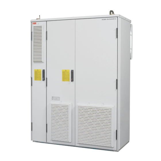
ABB ACS800-67 Hardware Manual (112 pages)
+C236 Wind Turbine Convert for Asynchronous Slip Ring Generators
Brand:
ABB
| Category:
Media Converter
| Size: 17.33 MB
Table of Contents
Safety Instructions
5
Contents of this Chapter
5
Use of Warnings and Notes
5
Installation and Maintenance Work
6
Grounding
9
Fibre Optic Cables
10
Operation
10
Table of Contents
11
Table of Contents
17
About this Manual
17
Contents of this Chapter
17
Compatibility
17
Safety Instructions
17
Reader
17
Contents
17
Installation and Commissioning Flowchart
18
Terms and Abbreviations
19
Hardware Description
21
Contents of this Chapter
21
Acs800-67
21
Grid-Side and Rotor-Side Converters
22
Voltage and Current Waveforms
23
Distortion
24
Mechanical Construction
26
Single Line Diagram
27
Cabinet Layout
28
Grid Supply and Stator Connections
31
Grid-Side Converter Supply
32
Over Voltage Protection
32
Auxiliary Voltage
32
Arc Protection
32
Functional Description
33
Control Boards and Optional Modules
34
Rdcu-12C
34
Ndcu-33Cx
34
Rdco-02C
34
Ntac-02
34
Ncan-02C
34
Neta-21C+Nexa-21C
34
Apbu-44C
34
Raio-01
35
Charging Circuit
35
Safety Functions
35
Modules
39
Converter Module
39
ALCL Filter Module
40
BLCL Filter Module
41
Heating and Cooling
42
Crowbar
42
Active Crowbar
42
Crowbar Resistor
43
Du/Dt Filter
43
Control Section
43
Interboard Connection Diagram
44
Cooling and Heating Logic
45
Type Code
47
Basic Code
47
Mechanical Installation
49
Contents of this Chapter
49
General
49
Required Tools
49
Moving the Unit
50
By Crane
50
By Fork-Lift or Pallet Truck
50
On Rollers
51
Final Placement of the Unit
51
Before Installation
52
Delivery Check
52
Installation Procedure
53
Miscellaneous
54
Cable Conduit in the Floor below the Cabinet
54
Electric Welding
55
Planning the Electrical Installation
57
Contents of this Chapter
57
Checking the Compatibility of the Generator
57
Protecting the Generator Winding and Bearings
57
Grid Connection
58
Disconnecting Device (Disconnecting Means)
58
Thermal Overload and Short Circuit Protection
58
Protection against Short Circuit in Stator Cable
58
Protection against Short Circuit Inside the Power Cabinet
58
Protection against Short Circuit in Generator Rotor Cable
58
Protection against Short Circuit Inside the Cabinet
58
DC Fuses
59
Ground Fault Protection
59
Emergency Stop Devices
59
Restarting after an Emergency Stop
60
Selecting the Power Cables
60
General Rules
60
Power Cable Busbars
60
Alternative Power Cable Types
60
Supply Line Cable Connection for Low Power Supply
62
Supply Line Cable Connection for High Power Supply
62
Busbar Connection
62
Cable Bus System
63
Single Core Cables with Concentric Protective Shields
63
Rotor Cable Connection
64
Conduit
65
Armored Cable / Shielded Power Cable
65
Power Factor Compensation Capacitors
65
Equipment Connected to the Rotor Cable
65
Installation of Safety Switches, Contactors, Connection Boxes, Etc
65
Bypass Connection
65
Relay Output Contacts and Inductive Loads
67
Auxiliary Voltage Cables
67
Selecting the Control Cables
68
Relay Cable
68
Coaxial Cable (for Use with Advant Controllers AC 80 / AC 800M)
68
Connection of a Generator Temperature Sensor to the Converter I/O
69
Routing the Cables
69
Control Cable Ducts
70
Electrical Installation
71
Contents of this Chapter
71
Checking the Insulation of the Assembly
72
Rotor Cable
72
DC Busbars
72
DC and AC Busbars
73
Stator Side Connection Procedure
73
Grid and Rotor Connections
74
Connection Diagram
74
Grid Supply Connection
75
Connection Procedure
78
Control Connections
80
Connection Procedure
80
Control Unit NDCU-33Cx/Rdcu-12C
81
Voltage and Current Measurement Unit NUIM-61C
82
Signal Connection between Auxiliary Power Supply and Main Control System of the Fan
82
Terminal Block
82
Installation Checklist
85
Checklist
85
Start-Up
87
Contents of this Chapter
87
Start-Up Procedure
87
Basic Checks with no Voltage Connected
87
Connecting Voltage to Grid Terminals and Auxiliary Circuit
88
Starting the Grid-Side Converter
88
Control Program Set-Up
89
On-Load Checks
89
Maintenance
91
Contents of this Chapter
91
Safety Instructions
91
Maintenance Intervals
92
Checking and Replacing the Air Filters
92
Door Filter
92
Rear Ventilation Filters
93
Power Connections
94
Cooling Fans
94
Converter Module Fan Replacement
95
Frame R8I - Circuit Board Compartment Fan
96
Power Cabinet Cooling Fan Replacement
98
ALCL Filter Fan Replacement
98
BLCL Filter Fan Replacement
99
Heating Heater Replacement
100
Heatsinks
101
Capacitors
101
Capacitor Replacement
101
Other Maintenance Actions
101
Power Module Replacement
101
Leds
101
Technical Data
103
Contents of this Chapter
103
Converter and Filter Module Types
103
IEC Ratings
103
Grid-Side Converter IEC Ratings
103
Rotor-Side Converter IEC Ratings
103
Symbols
104
Derating
104
Temperature Derating
104
Altitude Derating
104
Dimensions, Noise, Cooling Characteristics of the Modules
104
AC Fuses
105
DC Fuses
105
Rotor-Side Converter DC Fuses
105
Power Consumption of Auxiliary Devices
105
Breaker Settings
106
Cable Terminals
107
Input Power Cable Connection
107
Rotor Connection
107
Efficiency
107
Cooling and Noise
107
Degrees of Protection
107
Ambient Conditions
108
Materials
108
Compliance with the Machinery Directive
109
Free Space Requirements
109
Further Information
111
Product and Service Inquiries
111
Product Training
111
Providing Feedback on ABB Drives Manuals
111
Document Library on the Internet
111
Advertisement
ABB ACS800-67 System Description And Start-Up Manual (120 pages)
wind turbine converters
Brand:
ABB
| Category:
Media Converter
| Size: 3.43 MB
Table of Contents
List of Related Manuals
2
Table of Contents
5
1 About this Manual
9
What this Chapter Contains
9
Applicability
9
Safety Instructions
9
Target Audience
10
Purpose of the Manual
10
Contents of this Manual
10
Contents of Other Related Manuals
11
Drivewindow
11
Further Information
12
Terms and Abbreviations
12
2 System Description
13
What this Chapter Contains
13
General
13
Acs800-67
14
Wind Turbine System with Low Voltage Stator (690 V)
15
Wind Turbine System with Medium Voltage Stator (> 1000 V)
15
Converter System
16
Control of Generator Power
18
Operational Speed Range of a Typical Wind Turbine
19
Wind Turbine System Operating Speed Area
20
Control of Torque and Reactive Power Via Rotor-Side Converter
21
Control of Torque and Reactive Power Via Grid-Side Converter
25
Overview of Converter Interfaces
27
Converter Control
28
General
28
PLC Interface
28
Fieldbus Control
29
Grid Codes
30
Example of Grid Code Regulations in Different Countries
30
Example Limit Curves
31
Description of Parameter Settings
31
Grid Fault Ride-Trough Capability
32
Grid Support
34
Grid Support Areas
34
Grid Support Example
35
Stator Circuit Connection to Grid
36
Stator Breaker Only (Par. 16.20 GRID CONNECT MODE Set to MCB3)
36
Main Circuit Breaker (Par. 16.20 GRID CONNECT MODE Set to MCB1+MCB3/A)
37
Main Circuit Breaker (Par. 16.20 GRID CONNECT MODE Set to MCB1+MCB3/B)
37
Stator Contactor (Par. 16.20 GRID CONNECT MODE Set to MCB1+MCB3/C)
38
Settings
38
Grid Connection Procedure
39
Phasing Checks Executed at Start-Up
40
Grid Phasing
40
Encoder Phasing
40
Stator Phasing
40
Rotor Phasing
40
3 Start-Up with Low Voltage Stator
41
What this Chapter Contains
41
How to Start-Up the Converter
42
Safety
42
Power-Up
42
Manual Start-Up Data Entering
42
Time Setting
45
Digital Inputs
45
Grid-Side Converter and Crowbar Test
45
Grid-Side Converter and DC Chopper Test
48
Rotor-Side Converter Test
50
Stator Voltage Synchronization Test
51
Start-Up of the Air Damper
53
Final Settings
54
4 Start-Up with Medium Voltage Stator
55
What this Chapter Contains
55
How to Start-Up the Converter
56
Safety
56
Power-Up
56
Manual Start-Up Data Entering
56
Time Setting
58
Digital Inputs
58
Grid-Side Converter and Crowbar Test
59
Rotor-Side Converter Test
62
Stator Voltage Synchronization Test
63
Start-Up of the Air Damper
65
Final Settings
66
Starting Sequence
67
Start-Up Measurements
70
Stator Current Transformer Polarity Check
70
Phase U Test
70
Phase W Test
72
Test at Zero Speed
73
Start in Local Control Mode
74
Voltage and Current Waveform Examples
75
5 Practical Examples
77
What this Chapter Contains
77
Setting up the Fieldbus
77
Fieldbus Interfaces
77
Entering Start-Up Data and Torque Settings
78
Calculating/Setting the Motor Nominal Torque
78
Torque Set-Point
78
Stator Current and Voltage Measurement
79
NUIM-6X Voltage Measurement
79
NUIM-1X Voltage Measurement
79
NUIM-1X and NUIM-6X Current Measurements
79
Generator Data
81
Generator Rating Plate Equivalent Circuit Parameters
81
Parameters of Parameter Group 99
83
Parameter 99.05 MOTOR NOM SPEED
84
Generator Nominal Power Calculation
85
Setting the Equivalent Circuit Values to the Parameters
85
Mutual Inductance XM and Rotor Resistance Rr Calculations
86
Current Measurement of the Grid-Side Converter
87
Example
88
ABB Drives Communication Profile
90
Starting Sequence
90
Fault Sequence, Profile B
91
Normal Stop Sequence, Profile B
91
Starting Sequence When the Grid-Side Converter Is Started First Separately
92
Normal Start and Stop Sequence, ABB Drives Profile
93
Datasets
93
Fieldbus Signals
93
Configuring the NETA-01 Ethernet Adapter Module
94
Creating a Full Backup Package and Saving It in .BPG Format
96
Backup Package
97
Restoring a Backup File into the RDCU or NDCU Board
98
Saving a Parameter File (.Dwp) to the PC
100
Downloading Parameters into the Converter
101
Updating the Firmware
102
Communication Parameter Settings
103
Rotor-Side Converter
103
Grid-Side Converter
104
Changing the Rotation Direction of the Generator
105
General
105
Clockwise Rotation at Drive End (D End)
105
Counterclockwise Rotation at Drive End (D End)
106
Downloading the Diagnostics of APBU Branching Unit
107
Setting the Parameters According to Grid Code
108
Spanish Grid Code
108
Italian Grid Code
109
UK Grid Code
111
6 Tracing the Source of Warnings, Limits and Faults
113
What this Chapter Contains
113
Warnings
113
Limits
113
Torque Limit
113
Power Limit
113
Faults
114
How to Identify the Fault and What to Do in a Specific Fault Situation
114
Warning and Fault Messages
114
Checking the Phase Sequence of Grid-Side Converter Voltage Measurement
115
NUIM Board in Use (Grid-Side Converter Control Program Ixxr72Xx)
115
NAMU / BAMU Board in Use (Grid-Side Converter Control Program Iwxr74Xx)
116
Faults in Measurements
117
Product and Service Inquiries
119
Advertisement
Related Products
ABB ACS800-67LC
ABB ACS880-1604
ABB ACS880-1607
ABB ACS880-1604LC
ABB ACS880-1607LC
ABB ACS880-87LC-4000A/4021A-7
ABB ACS880-87LC-4000A/4132A-7
ABB ACS880-87LC-3200A
ABB ACS880-87LC-3200A-7
ABB ACS880-77CC
ABB Categories
Industrial Equipment
Controller
Measuring Instruments
Battery Charger
DC Drives
More ABB Manuals
Login
Sign In
OR
Sign in with Facebook
Sign in with Google
Upload manual
Upload from disk
Upload from URL