ABB ACSM1 Control Panel User Manual
Hide thumbs
Also See for ACSM1 Control Panel:
- Manual (510 pages) ,
- Firmware manual (448 pages) ,
- Hardware manual (112 pages)
Table of Contents
Advertisement
Quick Links
Advertisement
Table of Contents

Related Manuals for ABB ACSM1 Control Panel


Summary of Contents for ABB ACSM1 Control Panel
- Page 1 ACSM1 User’s Guide ACSM1 Control Panel...
- Page 2 3AUA0000031517 (English) Safe Torque Off Function (STO) Application Guide – 3AFE68929814 (English) System Engineering Manual – 3AFE68978297 (English) ACSM1 Fieldbus Control with FPBA-01 PROFIBUS DP Adapter Module and ABB AC500 PLC; Application Guide – 3AUA0000049359 (English) OPTION MANUALS FIO-01 Digital I/O Extension User’s Manual* – 3AFE68784921 (English) FIO-11 Analog I/O Extension User’s Manual* –...
- Page 3 ACSM1 Control Panel User’s Guide 3AUA0000020131 Rev B EFFECTIVE: 2009-08-12 © 2009 ABB Oy. All Rights Reserved.
-
Page 5: Table Of Contents
Providing feedback on ABB Drives manuals ........ - Page 6 How to select the monitored signals ..........22 How to set the speed, frequency, torque or position reference in the Output mode .
-
Page 7: About The Manual
Product and service inquiries Address any inquiries about the product to your local ABB representative, quoting the type code and serial number of the unit in question. A listing of ABB sales, support and service contacts can be found by navigating to www.abb.com/drives... - Page 8 About the manual...
-
Page 9: Hardware Description
Hardware description What this chapter contains The chapter describes the control panel keys. It also instructs in using the panel in control, monitoring and changing the settings. About control panels Use a control panel to control the ACSM1, read status data, and adjust parameters. Compatibility The manual is compatible with the ACSM1 drive control panel SW rev 3.05 and Flash rev 3.4.1.6 or later. -
Page 10: Acsm1 Control Panel
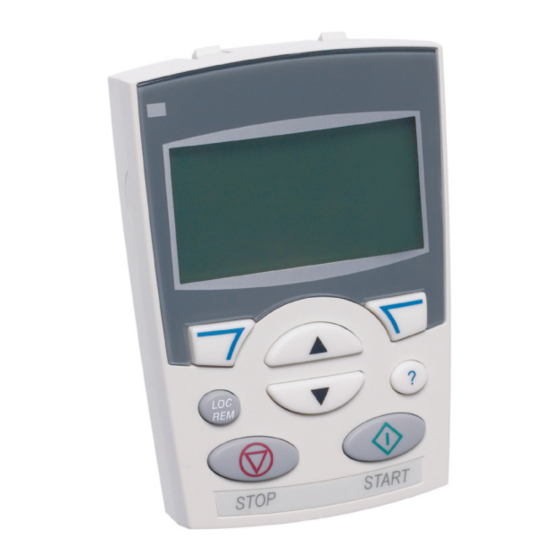
ACSM1 Control Panel Features The ACSM1 Control Panel features: • alphanumeric control panel with an LCD display • context sensitive help • real time clock. Overview The following table summarizes the key functions and displays on the ACSM1 Control Panel. -
Page 11: Status Line
Status line The top line of the LCD display shows the basic status information of the drive. MAIN MENU 30.00rpm No. Field Alternatives Significance 1 Control location Drive control is local, that is, from the control panel. Drive control is remote, such as the drive I/O or fieldbus. - Page 12 Hardware description...
-
Page 13: Installation
ACSM1-04 Drive Modules Hardware Manual [3AFE68797543 (English)]. Control panel / PC connection The cable CAT5 straight-through network cable (max. 3 m) can be used. The cable is available from ABB, but other cables fulfilling the specifications of that cable can be used. Installation... -
Page 14: Mounting The Control Panel
Mounting the control panel There are two panel mounting kits, IP21 (68294673) and IP66 (68829593). The kits contain an extension cable, a gasket and other mounting accessories needed for installing the panel to the cabinet door. The kits also contain installation instructions as drawings, see the figures below. -
Page 15: Mounting Template
Mounting template Installation... -
Page 16: Gasket
Gasket Installation... -
Page 17: Operation
The left soft key is used to cancel the made changes and return to the previous operation level. The ACSM1 Control Panel has six options in the Main menu: Parameters, Fault Logger, Time & Date, Parameter Backup, Reference Edit and Drive Info. In addition, the control panel has an Output mode, which is used as default. -
Page 18: List Of Tasks
Initially, the panel is in the Output mode, where you can 30.00rpm start, stop, change the direction, switch between local and remote control, modify the reference value and monitor up to three actual values. To do other tasks, go first to the Main menu and select the appropriate option on the 00:00 MENU... -
Page 19: Help And Panel Version - Any Mode
Help and panel version – Any mode How to get help Step Action Display Press to read the context-sensitive help text for the item that is highlighted. TIME & DATE TIME FORMAT DATE FORMAT SET TIME SET DATE DAYLIGHT SAVING EXIT 00:00 HELP... -
Page 20: Basic Operations - Any Mode
Basic operations – Any mode How to start, stop and switch between local and remote control You can start, stop and switch between local and remote control in any mode. To be able to start or stop the drive by using the control panel, the drive must be in local control. -
Page 21: Output Mode
Output mode In the Output mode, you can: • monitor actual values of up to three signals • change the direction of the motor rotation • set the speed, frequency, torque or position reference • adjust the display contrast • start, stop, change the direction and switch between local and remote control. You get to the Output mode by pressing EXIT repeatedly. -
Page 22: How To Select The Monitored Signals
How to select the monitored signals Step Action Display You can select which signals are monitored in the Output mode and how they PAR EDIT are displayed with group 17 PANEL DISPLAY parameters. See page 1701 SIGNAL1 PARAM 01.03 detailed instructions on changing parameter values. CANCEL 00:00 NEXT... -
Page 23: How To Set The Speed, Frequency, Torque Or Position Reference In The Output Mode
How to set the speed, frequency, torque or position reference in the Output mode See also section Reference Edit on page 42. Step Action Display EXIT 30.00rpm If you are not in the Output mode, press repeatedly until you get there. 00:00 MENU 30.00rpm... -
Page 24: Parameters
Parameters In the Parameters option, you can: • view and change parameter values • start, stop, change the direction and switch between local and remote control. How to select a parameter and change its value Step Action Display MENU Go to the Main menu by pressing if you are in the Output mode, otherwise MAIN MENU PARAMETERS... -
Page 25: How To Change The Value Of Value Pointer Parameters
Step Action Display SAVE • To save the new value, press PARAMETERS 9901 LANGUAGE CANCEL • To cancel the new value and keep the original, press 9904 MOTOR TYPE PMSM 9906 MOT NOM CURRENT 9907 MOT NOM VOLTAGE EXIT 00:00 EDIT How to change the value of value pointer parameters In addition to the parameters shown above, there are two kinds of pointer... - Page 26 Step Action Display NEXT • To continue, press PAR EDIT CANCEL • To cancel the new value and keep the original, press 1501 AO1 PTR P.02.08 Specify a new parameter for the value pointer parameter to point to with keys 0208 AO1 .
-
Page 27: How To Change The Value Of Bit Pointer Parameter To Point To The Value Of A Bit In Another Signal
How to change the value of bit pointer parameter to point to the value of a bit in another signal The bit pointer parameter points to the value of a bit in another signal, or can be fixed to 0 (FALSE) or 1 (TRUE). For the latter option, see page 29. The bit pointer parameter points to a bit value (0 or 1) of one bit in a 32-bit signal. - Page 28 Step Action Display Specify a new parameter group for the bit pointer parameter to point to with PAR EDIT keys . The parameter group changes respectively. 1204 DI01 OUT PTR P.06.01.00 06 DRIVE STATUS CANCEL 00:00 NEXT NEXT • To continue, press PAR EDIT CANCEL •...
-
Page 29: How To Change The Value Of Bit Pointer Parameter To Fixed 0 (False) Or 1 (True)
How to change the value of bit pointer parameter to fixed 0 (FALSE) or 1 (TRUE) The bit pointer parameter can be fixed to constant value of 0 (FALSE) or 1 (TRUE). When adjusting a bit pointer parameter on the control panel, CONST is selected in order to fix the value to 0 (displayed as C.FALSE.) or 1 (C.TRUE.). - Page 30 Step Action Display SAVE • To continue, press PARAMETERS 1201 DI01 CONF9901 CANCEL • To cancel the new value and keep the original, press 1202 DI02 CONF 1203 DI03 CONF The new value is shown in the parameters list. 1204 DI01 OUT PTR C.TRUE EXIT 00:00...
-
Page 31: Fault Logger
Fault Logger In the Fault Logger option, you can: • view the drive fault history • see the details of the most recent faults • start, stop, change the direction and switch between local and remote control. How to view faults Step Action Display... -
Page 32: Time & Date
• start, stop, change the direction and switch between local and remote control. The ACSM1 Control Panel contains a battery to ensure the function of the clock when the panel is not powered by the drive. How to show or hide the clock, change display formats, set the date and time... - Page 33 Step Action Display SET DATE • To set the date, select SET DATE on the menu and press . Specify the first part of the date (day or month depending on the selected date format) with 19.03.2008 keys , and press .
-
Page 34: Parameter Backup
Parameter Backup The Parameter Backup option is used to export parameters from one drive to another or to make a backup of the drive parameters. Uploading stores all drive parameters, including up to four user sets, to the control panel. Selectable subsets of the backup file can then be restored/downloaded from the control panel to the same drive or another drive of the same type (e.g. -
Page 35: How To Backup And Restore Parameters
How to backup and restore parameters For all backup and restore functions available, see page 34. Step Action Display MENU Go to the Main menu by pressing if you are in the Output mode, otherwise MAIN MENU FAULT LOGGER EXIT by pressing repeatedly until you get to the Main menu. - Page 36 Step Action Display PAR BACKUP • The display shows the transfer status as a percentage of completion. Restoring/downloading all parameters PAR BACKUP • Downloading finishes. Finishing restore operation Trying to restore parameters between different product variants If you try to backup and restore parameters between different product variants (ACSM1 Speed and ACSM1 Motion), the panel shows you the following information about incompatible versions: Step...
- Page 37 Parameter errors If you try to backup and restore parameters between different firmware versions, the panel shows you the following parameter error information: Step Action Display Restore operation starts normally. PAR BACKUP Initializing param. restore operation 00:00 Firmware version is checked. VER CHECK FIRMWARE VERSION You can see on the panel that the firmware versions are not the same.
- Page 38 Step Action Display The panel shows a list of erroneous parameters. PAR ERRORS 6005*POS UNIT VALUE MISSING 6008*POS2 INT SCALE READY 00:00 EDIT You can scroll the parameters with keys . The reason for PAR ERRORS 22114* parameter error is also shown. 1313*AI SUPERVIS ACT 0000 bin INCORRECT VALUE TYPE...
- Page 39 Step Action Display • If the downloading is continued, the display shows a message about it. PAR BACKUP Initializing param. restore operation 00:00 • Downloading continues, drive is being restarted. PAR BACKUP Restarting drive 00:00 PAR BACKUP • The display shows the transfer status as a percentage of completion. Restoring/downloading user set 1 PAR BACKUP...
- Page 40 Trying to load a user set between different firmware versions If you try load a user set between different firmware versions, the panel shows you the following fault information: Step Action Display Go to the Parameters option by selecting PARAMETERS on the main menu as PAR GROUPS 11 START/STOP MODE shown in section...
-
Page 41: How To View Information About The Backup
How to view information about the backup Step Action Display MENU Go to the Main menu by pressing if you are in the Output mode, otherwise MAIN MENU FAULT LOGGER EXIT by pressing repeatedly until you get to the Main menu. TIME &... -
Page 42: Reference Edit
Reference Edit In the Reference Edit option, you can: • accurately control the local reference value, • start, stop, change the direction and switch between local and remote control. Editing is allowed only in the LOC state, the option always edits the local reference value. -
Page 43: Drive Info
Drive Info In the Drive Info option, you can: • view information on the drive, • start, stop, change the direction and switch between local and remote control. How to view drive info Step Action Display MENU Go to the Main menu by pressing if you are in the Output mode, otherwise MAIN MENU PAR BACKUP... - Page 44 Operation...
- Page 46 ABB Oy AC Drives P.O. Box 184 FI-00381 HELSINKI FINLAND Telephone +358 10 22 11 +358 10 22 22681 Internet www.abb.com...