
Related Manuals for ABB ACS-AP-I


Summary of Contents for ABB ACS-AP-I
- Page 1 — OPTIONS FOR ABB DRIVES ACS-AP-I, -S, -W and ACH-AP-H, -W Assistant control panels User's manual...
- Page 3 ACS-AP-I, -S, -W and ACH-AP-H, -W Assistant control panels User's manual Table of contents 3AUA0000085685 Rev F Original instructions EFFECTIVE: 2022-01-27...
-
Page 5: Table Of Contents
Table of contents 5 Table of contents 1 Introduction to the manual What this chapter contains ............... Applicability ..................Compatibility ..................Safety ....................Intended audience ................. Related manuals ................... 2 Installation and start-up What this chapter contains ............... Installation ................... First start-up .................. - Page 6 6 Table of contents Common user tasks ................Basic operation of the drive ..............Parameters ..................System information and help ..............Faults and warnings ................Basic settings and assistants ..............Backups ..................5 Functions in the main Menu What this chapter contains ............... Menu ....................
- Page 7 Table of contents 7 7 Control of multiple drives What this chapter contains ............... Connecting multiple drives to a control panel ..........Selecting drive menu ................Selecting a drive ................Panel features with multiple drives .............. Panel views ..................The Help page .................. Graph data ..................
- Page 8 8 Table of contents LCD specifications ................. Bluetooth interface ................. Bluetooth encryption ................Bluetooth radio frequency exposure ............Bluetooth (BT) .................. Bluetooth Low Energy (BLE) ..............FCC and Industry Canada certifications ............FCC ID: 2AFNGAPWSERIES ..............IC: 20555-APWSERIES ............... Markings ..................... Disclaimers ..................
-
Page 9: Introduction To The Manual
Introduction to the manual 9 Introduction to the manual What this chapter contains This chapter describes the applicability, compatibility, intended audience and the contents of this manual. -
Page 10: Applicability
10 Introduction to the manual Applicability This manual applies to the following panel types and their versions: Control panel type ACS-AP-I and ACS-AP-W ACH-AP-H ACH-AP-W ACS-AP-S Hardware version C or later A or later C or later A or later Software version 4.61 or later... -
Page 11: Safety
Introduction to the manual 11 Safety Follow all safety instructions delivered with the drive. Intended audience This manual is intended for persons who use the ACS-AP-I, ACS-AP-S, ACS-AP-W, ACH-AP-H or ACH-AP-W Assistant control panels. Related manuals Tool and maintenance manuals... -
Page 13: Installation And Start-Up
Installation and start-up 13 Installation and start-up What this chapter contains This chapter describes how to install and start-up the Assistant control panel for the first time. -
Page 14: Installation
14 Installation and start-up Installation Attach the control panel directly to the drive or use a separate mounting kit (for example, for cabinet door mounting). To attach the control panel, Place its bottom end into the bottom of the slot in the drive (A). Pivot the control panel and push the upper part (B) until you hear a click. -
Page 15: First Start-Up
Installation and start-up 15 First start-up To start-up the control panel for the first time, follow the instructions: Obey all drive-specific safety precautions. Install the control panel. See instructions in Installation (page 14). Power up the drive. The control panel start-up begins automatically. Wait until the control panel shows the language selection view. - Page 16 16 Installation and start-up Once you are in the Home view, the control panel is ready for use.
-
Page 17: Control Panel Overview
Control panel overview 17 Control panel overview What this chapter contains This chapter describes the display, keys and main parts of the Assistant control panel. -
Page 18: Display, Keys And Parts
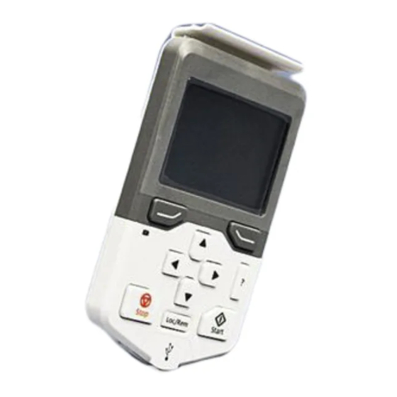
18 Control panel overview Display, keys and parts Display USB connector Left softkey Clip Right softkey RJ-45 connector Status LED Type code label on the panel Help Battery cover Arrow keys Stop (see Start and Stop) Hand Start (see Start and Stop) Auto Local/Remote (see Loc/Rem) -
Page 19: Display
Control panel overview 19 Display ■ In most views, the following control panel elements are shown on the display: Control location and Indicates how the drive is controlled: related icons No text: The drive is in local control, but controlled from another device. The icons in the top pane indicate which actions are allowed. - Page 20 20 Control panel overview Drive name If a name is given, it is displayed at the top pane. By default, it is blank. You can change the name in the Primary settings (page 49) Settings (page 48) menu. Reference value Speed, frequency and so on, are shown with its unit.
-
Page 21: Keys
Control panel overview 21 Keys ■ The keys of the control panel are described below. Left softkey The left softkey ( ) is usually used for exiting and canceling. Its function in a given situation is shown by the softkey selection in the bottom left corner of the display. Holding down exits each view in turn until you are back in the Home view. -
Page 22: Auto
22 Control panel overview Auto The Auto key ( ) is used to run the drive automatically. The control is selected from primary or secondary or any DI. You can give the reference inputs in Menu → Primary settings → Drive or by setting the values in parameter groups 19 and 20. Loc/Rem The location key ( Loc/Rem... -
Page 23: Control Panel And Panel Platform/Holder Leds
Control panel overview 23 Control panel and panel platform/holder LEDs ■ The ACS-AP-… control panel has a status LED. The control panel mounting platform or holder has two status LEDs. For their indications, see the following table. Location Indication Control panel Continuous green The unit is functioning normally. -
Page 24: Rj-45 Connector
Type code label on the panel ■ The type code label on the panel contains revision information. See an example label below. ABB Oy, Hiomotie 13, 00380 Helsinki, Finland M/N: ACS-AP-W CODE: 3AXD50000025964 S/N: B1250121LL 3AXD50000025964B1250121LL Made in Country... -
Page 25: Battery Cover
Wireless interface ■ The ACS-AP-W and ACH-AP-W Assistant control panels with Bluetooth interface enable wireless interface for ABB drives. The wireless panels are also embedded with powerful processor and memory that enables faster communication. The functions of •... -
Page 27: Basic Operation
Basic operation 27 Basic operation What this chapter contains This chapter describes the basic operations and components of the user interface. It also lists the common user tasks and provides instructions to complete the task. User interface overview The user interface has the following main components: Component Description Home view... -
Page 28: Control Panel Navigation
28 Basic operation Control panel navigation Use the arrow keys and softkeys for navigation. Follow the choices on the screen. Menu Options Parameters Reference Assistants Direction change Energy efficiency Select drive Event log Edit Home view History graphs Active faults Active warnings Backups System info... -
Page 29: Home View
Basic operation 29 Home view The main view of the control panel is called Home view. In the Home view, you can monitor the status of the drive, such as its speed, torque or power. The Home view has one or more pages, each of which can display up to three signals. -
Page 30: Common User Tasks
30 Basic operation Common user tasks The following tables list common user tasks and describes how to complete the task. See chapters Functions in the main Menu (page 33) Functions in the Options menu (page 53) for detailed descriptions of functions in the menus. Note: The Menu options varies based on the drive/device to which the control panel is connected. -
Page 31: Basic Settings And Assistants
Basic operation 31 Task Actions Hide/view an active fault. Faults are automatically displayed. If you hide a fault by pressing (Hide), it automatically reappears after 60 seconds of no key presses. You can also view the fault through Options > Active faults. -
Page 33: Functions In The Main Menu
Functions in the main Menu 33 Functions in the main Menu What this chapter contains This chapter describes the functions in the main Menu. -
Page 34: Menu
34 Functions in the main Menu Menu All functions of the control panel are accessed through the Menu which is the main menu of the user interface. The sub-menus of the Menu are listed below and they are described in more detail in the subsequent sections. The submenus depend on the product that is controlled with the control panel. -
Page 35: Parameters
Functions in the main Menu 35 Parameters In the Parameters menu, you can view and edit parameters. There are four sub-menus through which you can access the parameters. In each sub-menu, the grouping principle of the parameters is different. In each sub-menu, you can edit a parameter by highlighting it and pressing (Edit). -
Page 36: Editing The List Of Favorites
36 Functions in the main Menu Editing the list of favorites Select Edit. Check parameters you want to show on the list by pressing (Select). Press (Done) to exit and save changes. Modified ■ In the Modified sub-menu, only the parameters whose values differ from the Application Macro defaults are listed. -
Page 37: Editing Parameters
Functions in the main Menu 37 • Press (Back) to go back to the parameter view. Editing the Home view functions are described in more detail in Editing the contents of the Home view (page 54). Editing parameters ■ You can edit parameter values with the arrow keys. Press (Select) to select the desired parameter from the list. - Page 38 38 Functions in the main Menu • to move the cursor. • Press (Save) to select and save the highlighted option. • To cancel and exit, press (Cancel). Some selection list parameters allow you to choose another parameter as its value. In addition to a preset list of options, you can select a parameter freely, represented by the selection Other in the list.
-
Page 39: Editing Bit-Field Parameters
Functions in the main Menu 39 Press to move to a bit selection list. If you want to select all the bits in the parameter, press (Save) instead. Select a bit if applicable (see the previous step). Press to invert the selected bit and press (Save) to save the selection. -
Page 40: Editing Texts
40 Functions in the main Menu Editing texts ■ Texts that you can edit with the control panel include parameter display names in the Home view and their units, drive names, fault and warning names, and other customizable notes or names. •... -
Page 41: Assistants
You can also generate a QR code, which is an optical code containing information of the drive. The code can be read with ABB application and mobile device. Launching an assistant ■... -
Page 42: Generating A Qr Code
42 Functions in the main Menu Generating a QR code ■ In the Assistants menu, select QR code using and press (Select). Press (Continue). The control panel collects data and generates the code. Press << or >> to navigate to the next screen. You can also generate QR code from Menu →... -
Page 43: Event Log
Functions in the main Menu 43 Event log In the Event log menu, you can view information collected on faults and warnings. Events are automatically logged. See Fault tracing (page 63) for more information on faults and warnings. • Faults sub-menu displays the faults that are tripped the drive. •... -
Page 44: Load Profile
44 Functions in the main Menu Load profile ■ In the Load profile submenu, you can view and configure load profiles. The menu contains the following sub-menus: • Amplitude logger 1: Opens a Histogram view, which displays the motor current as a distribution histogram. -
Page 45: Creating A Parameter Backup
Functions in the main Menu 45 waits for 24 hours before checking if there are additional parameter changes. If there are, it creates a new backup overwriting the previous one. You can copy backup files to and from a PC with any file manager application (example, Windows Explorer). -
Page 46: System Info
46 Functions in the main Menu Note: This functionality is available in a future release. Select one of the restore options: • To restore all settings, select Restore all parameters. • To restore a set of parameters, select Select par restore group and select the desired parameters from the list, and then select Restore. - Page 47 Functions in the main Menu 47 Sub-menu Function Drive Shows information on the selected component, such as firmware version, serial number, type code, device ID number or date of manufacture. Note: The content of the view varies between different drive types. Control panel Shows information on the hardware and software version of the control panel.
-
Page 48: Settings
Sub-menu Function QR code Shows an optical code containing information of the drive. The code can be read with ABB application and mobile device. To generate the QR code, press (Continue). The control panel collects data and creates the code. -
Page 49: Primary Settings
Functions in the main Menu 49 Sub-menu Function Date & time Set date and time, and select their display settings and whether the control panel auto- matically adjusts the time for daylight savings changes. The time and date display setting determines how time stamps are formatted. -
Page 50: I/O
50 Functions in the main Menu Sub-menu Function Motor Adjust motor-related settings, such as control mode, nominal values, ID run or thermal protection. Note that the settings that are visible depend on other selections, for example vector or scalar control mode, used motor type or selected start mode. Loop controller Set up loop controller settings and actual values. - Page 51 Functions in the main Menu 51 Sub-menu Function Start, stop, reference, Shows where the drive is currently taking its start, stop commands and reference. The summary view is updated in real time. If the drive is not starting or stopping as expected, or runs at undesired speed, use this view to find out where the control comes from.
-
Page 53: Functions In The Options Menu
Functions in the Options menu 53 Functions in the Options menu What this chapter contains This chapter describes functions in the Options menu. Options menu In the Options menu, you can control the settings related to the Home view. Note: The contents displayed may vary based on the drive/device to which the panel is connected. -
Page 54: Setting The Reference
54 Functions in the Options menu Sub-menu Function Select drive Enable or disable the panel bus. If enabled, view the status of drives in the panel bus and select which drive to control with the control panel. See chapter Control of multiple drives (page 59). - Page 55 Functions in the Options menu 55 Two-signal page in editing mode Empty page in editing mode Softkey labels and a blinking cursor indicate that the control panel is In the editing mode, use to move between the different pages of the Home view.
- Page 56 56 Functions in the Options menu For bit field parameters, you can select either a single bit or the full bit field to add to the Home view. With individual bits, the bit state is displayed. Full bit fields are shown in either hexadecimal or binary format.
- Page 57 Functions in the Options menu 57 Display signal min as Display signal max as display value 100.00 -50.00 actual min actual max -32767 32768 Signal max Signal min 6000 -3000 actual value • Display unit: Customize the unit shown in Home view when scaling is used.
-
Page 59: Control Of Multiple Drives
Control of multiple drives 59 Control of multiple drives What this chapter contains This chapter describes how to control several drives with one control panel. Connecting multiple drives to a control panel Connect the control panel (A) to the first drive (B) in the panel bus. Connect the first drive (C) to the second (D), the second to the third, and so on, by daisy chaining RJ-45 leads. -
Page 60: Selecting Drive Menu
60 Control of multiple drives The picture shows panel bus example with ACS880-01 drives. The ACX580 and ACX480 drives have dedicated panel bus adapters with two RJ-45 slots. Selecting drive menu In the Options menu, select Select drive which lists all the drives connected to the panel bus and shows their current status. -
Page 61: Panel Features With Multiple Drives
Control of multiple drives 61 Panel features with multiple drives Panel views ■ In a panel bus configuration, the control panel communicates with one drive at a time. Any information shown on the control panel, such as the status bar or signals in the Home view pertain to the currently selected drive. -
Page 62: Faults And Warnings With Multiple Drives
62 Control of multiple drives Faults and warnings with multiple drives Faults and warnings in the currently selected drive ■ Faults and warnings in the currently selected drive are shown as normal. Faults and warnings in other drives ■ Faults in the other drives in the panel bus appear as remote faults. Faults that require a restart look like any other remote faults. -
Page 63: Fault Tracing
Fault tracing 63 Fault tracing What this chapter contains This chapter describes how to identify different fault and warning messages that are shown on the control panel and how to solve problem situations. Identifying error and warning messages Faults and warnings are drive states that occur when the drive detects a problem in its operation. - Page 64 64 Fault tracing Display Type continuous red Faults (page 65). blinking red Faults of this type require stopping and restarting the drive before it continues to function normally. Faults (page 65). continuous red A fault has occurred in another drive in the panel bus.
-
Page 65: Faults
Fault tracing 65 Faults Faults are problems that require your attention before you start the drive again. Refer the following steps to solve the fault situation: Identify and eliminate the cause of the fault. In the Fault view, you can see the fault code. -
Page 67: Maintenance
Maintenance 67 Maintenance What this chapter contains This chapter describes the service and maintenance tasks of the Assistant control panel. -
Page 68: Removing The Control Panel Cover
68 Maintenance Removing the control panel cover It is possible to remove the control panel cover to clean any dust inside the cover or to change the cover to customize the control panel. The cover consists of two parts, both of which can be removed. You do not need tools to remove the covers. -
Page 69: Control Panel Software Updates
Dispose of the old battery according to local disposal rules or applicable laws. Note: Contact ABB for ZCU-12 (Supply control unit) battery replacement. Control panel software updates If the control panel software needs to be updated, contact ABB. Recycling instructions and environmental information See the drive related Recycling instructions and environmental information. -
Page 71: Panel-To-Pc Usb Connection
Panel-to-PC USB connection 71 Panel-to-PC USB connection What this chapter contains This chapter describes the USB connection between the Assistant control panel and a PC. USB connection The three main functions of the USB connection are: • The control panel acts as an USB adapter, allowing the PC tool to interact with the drive. -
Page 72: Connecting Control Panel To Pc Usb
72 Panel-to-PC USB connection Connecting control panel to PC USB Note: When connected to a PC, the control panel displays the USB screen and does not respond to key presses. In this mode, you can only interact with the control panel or the drive through the PC tool. -
Page 73: Connecting A Pc Tool To A Drive Through The Control Panel
Connecting a PC tool to a drive through the control panel You can use the control panel to connect an ABB PC tool to the drive. When using the control panel, you can only access the drive from the PC tool. -
Page 75: Technical Data
Technical data 75 Technical data What this chapter contains This chapter contains the technical details of the Assistant control panel. Connectors The control panel has the following connectors: Connector Purpose RJ-45 female connector Used for connecting the panel to drive. •... -
Page 76: Dimensions And Weight
76 Technical data Dimensions and weight Weight 130 g Height, width and depth mm [in.] Degrees of protection Degree of protection, attached to a drive IP55 Separately IP20 When control panels are connected in stand-alone to RJ-45 cable IP20 When control panels are connected with USB cable. IP20 Control panel mounted to DPMP-01 IP55... -
Page 77: Environmental Limits
Technical data 77 Environmental limits Operation Storage Transportation Installation site altitude 4000 m (13123 ft.) Air temperature -20 °C to +55 °C -40 °C to +70 °C -40 °C to +70 °C (-4 °F to 131 °F) (-40 °F to 158 °F) (-40 °F to 158 °F) Relative humidity 95% (non-condensing) -
Page 78: Bluetooth Encryption
78 Technical data Operating frequency 2.4000...2.4835 GHz Antenna gain Maximum 1.7 dBi Bluetooth encryption Bluetooth classic Bluetooth LE (low energy) Encryption algorithm Custom algorithms based on: • SAFER + for key derivation (called E21 and E22) • authentication as message authentication codes (called E1) •... -
Page 79: Ic: 20555-Apwseries
Note: Modifications not expressly approved by ABB Oy could void the user's authority to operate the wireless panels. IC: 20555-APWSERIES ■... -
Page 80: Cybersecurity Disclaimer
Notwithstanding any other provision to the contrary and regardless whether the contract is terminated or not, ABB and its affiliates are under no circumstances liable for damages and/or losses related to such security breaches, any unauthorized access, interference, intrusion, leakage and/or theft of data or information. - Page 81 Product and service inquiries Address any inquiries about the product to your local ABB representative, quoting the type designation and serial number of the unit in question. A listing of ABB sales, support and service contacts can be found by navigating to www.abb.com/searchchannels.
- Page 82 3AUA0000085685F © Copyright 2022 ABB. All rights reserved. Specifications subject to change without notice.