Mitsubishi Electric MELSEC iQ-R Series User Manual
Profinet io device module
Hide thumbs
Also See for MELSEC iQ-R Series:
- Programming manual (2110 pages) ,
- User manual (760 pages) ,
- Reference manual (498 pages)
Table of Contents
Advertisement
Advertisement
Table of Contents

Related Manuals for Mitsubishi Electric MELSEC iQ-R Series


Summary of Contents for Mitsubishi Electric MELSEC iQ-R Series
- Page 1 MELSEC iQ-R PROFINET IO Device Module User's Manual (Startup) -RJ71PN93...
-
Page 3: Safety Precautions
SAFETY PRECAUTIONS (Read these precautions before using this product.) Before using this product, please read this manual and the relevant manuals carefully and pay full attention to safety to handle the product correctly. The precautions given in this manual are concerned with this product only. For the safety precautions of the programmable controller system, refer to the user's manual for the CPU module used. - Page 4 [Design Precautions] WARNING ● Configure safety circuits external to the programmable controller to ensure that the entire system operates safely even when a fault occurs in the external power supply or the programmable controller. Failure to do so may result in an accident due to an incorrect output or malfunction. (1) Emergency stop circuits, protection circuits, and protective interlock circuits for conflicting operations (such as forward/reverse rotations or upper/lower limit positioning) must be configured external to the programmable controller.
- Page 5 [Design Precautions] WARNING ● Especially, when a remote programmable controller is controlled by an external device, immediate action cannot be taken if a problem occurs in the programmable controller due to a communication failure. To prevent this, configure an interlock circuit in the program, and determine corrective actions to be taken between the external device and CPU module in case of a communication failure.
- Page 6 [Installation Precautions] WARNING ● Shut off the external power supply (all phases) used in the system before mounting or removing the module. Failure to do so may result in electric shock or cause the module to fail or malfunction. [Installation Precautions] CAUTION ●...
- Page 7 [Wiring Precautions] WARNING ● Shut off the external power supply (all phases) used in the system before installation and wiring. Failure to do so may result in electric shock or cause the module to fail or malfunction. ● After installation and wiring, attach a blank cover module (RG60) to each empty slot and an included extension connector protective cover to the unused extension cable connector before powering on the system for operation.
- Page 8 [Wiring Precautions] CAUTION ● Individually ground the FG and LG terminals of the programmable controller with a ground resistance of 100 ohms or less. Failure to do so may result in electric shock or malfunction. ● Use applicable solderless terminals and tighten them within the specified torque range. If any spade solderless terminal is used, it may be disconnected when the terminal screw comes loose, resulting in failure.
- Page 9 [Startup and Maintenance Precautions] WARNING ● Do not touch any terminal while power is on. Doing so will cause electric shock or malfunction. ● Correctly connect the battery connector. Do not charge, disassemble, heat, short-circuit, solder, or throw the battery into the fire. Also, do not expose it to liquid or strong shock. Doing so will cause the battery to produce heat, explode, ignite, or leak, resulting in injury and fire.
- Page 10 [Startup and Maintenance Precautions] CAUTION ● When connecting an external device with a CPU module or intelligent function module to modify data of a running programmable controller, configure an interlock circuit in the program to ensure that the entire system will always operate safely. For other forms of control (such as program modification, parameter change, forced output, or operating status change) of a running programmable controller, read the relevant manuals carefully and ensure that the operation is safe before proceeding.
- Page 11 [Operating Precautions] CAUTION ● When changing data and operating status, and modifying program of the running programmable controller from an external device such as a personal computer connected to an intelligent function module, read relevant manuals carefully and ensure the safety before operation. Incorrect change or modification may cause system malfunction, damage to the machines, or accidents.
- Page 12 [Disposal Precautions] CAUTION ● When disposing of this product, treat it as industrial waste. ● When disposing of batteries, separate them from other wastes according to the local regulations. For details on battery regulations in EU member states, refer to the MELSEC iQ-R Module Configuration Manual.
-
Page 13: Conditions Of Use For The Product
Notwithstanding the above restrictions, Mitsubishi Electric may in its sole discretion, authorize use of the PRODUCT in one or more of the Prohibited Applications, provided that the usage of the PRODUCT is limited only for the specific applications agreed to by Mitsubishi Electric and provided further that no special quality assurance or fail-safe, redundant or other safety features which exceed the general specifications of the PRODUCTs are required. -
Page 14: Introduction
Before using this product, please read this manual and the relevant manuals carefully and develop familiarity with the functions and performance of the MELSEC iQ-R series programmable controller to handle the product correctly. When applying the program examples provided in this manual to an actual system, ensure the applicability and confirm that it will not cause system control problems. -
Page 15: Table Of Contents
CONTENTS SAFETY PRECAUTIONS ..............1 CONDITIONS OF USE FOR THE PRODUCT . -
Page 16: Relevant Manuals
• Installation For details, refer to the following. MELSEC iQ-R Module Configuration Manual e-Manual refers to the Mitsubishi Electric FA electronic book manuals that can be browsed using a dedicated tool. e-Manual has the following features: • Required information can be cross-searched in multiple manuals. -
Page 17: Terms
Unless otherwise specified, this manual uses the following generic terms and abbreviations. Generic term/abbreviation Description CPU module An abbreviation for the MELSEC iQ-R series CPU module IO controller An abbreviation for the PROFINET IO controller IO device An abbreviation for PROFINET IO devices. These devices include the RJ71PN93. -
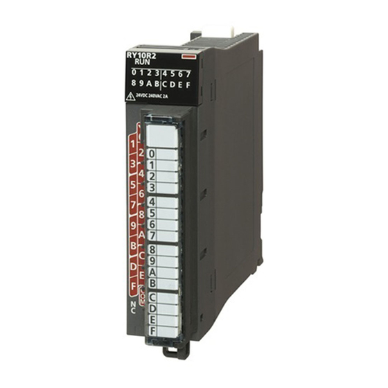
Page 18: Chapter 1 Part Names
PART NAMES This chapter describes the names of each part of the RJ71PN93. Name Description RUN LED Indicates the operating status. On: Normal operation Off: Error ( MELSEC iQ-R PROFINET IO Device Module User's Manual (Application)) ERR LED Indicates the error status of the RJ71PN93. On, flashing: Error (... - Page 19 MEMO 1 PART NAMES...
-
Page 20: Chapter 2 Specifications
SPECIFICATIONS Performance Specifications This section describes the performance specifications of the RJ71PN93. Item Description PROFINET communication specifications Conformance Class B Data exchange Maximum I/O data length 1024 bytes (Total size of the I/O data) Cycle time 512ms maximum 2ms minimum Transmission specifications Type 100BASE-TX/10BASE-T... - Page 21 MEMO 2 SPECIFICATIONS 2.1 Performance Specifications...
-
Page 22: Chapter 3 Function List
FUNCTION LIST The following tables list the functions of the RJ71PN93. For details on the functions, refer to the following. MELSEC iQ-R PROFINET IO Device Module User's Manual (Application) Data communications Function Description Data exchange Exchanges data between the RJ71PN93 and the IO controller at a specified cycle. Data consistency function Prevents data inconsistency between the buffer memory in the RJ71PN93 and the devices in the CPU module in I/O data exchanges. - Page 23 MEMO 3 FUNCTION LIST...
-
Page 24: Chapter 4 Procedures Before Operation
PROCEDURES BEFORE OPERATION This chapter describes the procedures before operation. Network construction Configure the system and set the parameters which are required for start-up. • Wiring ( Page 29 WIRING) • Parameter setting ( MELSEC iQ-R PROFINET IO Device Module User's Manual (Application)) For details on parameters for the IO controller, refer to the following. - Page 25 MEMO 4 PROCEDURES BEFORE OPERATION...
-
Page 26: Chapter 5 System Configuration
SYSTEM CONFIGURATION PROFINET Configuration This chapter describes the PROFINET configuration using an IO controller and the RJ71PN93s. (1) PROFINET configuration tool (2) Engineering tool (3) IO controller (4) RJ71PN93 In PROFINET, other PROFINET IO controllers or external devices that perform TCP/IP communications can be used on the same network. - Page 27 Star topology In a star topology, connect the RJ71PN93s (2) to the IO controller via a switching hub (3) as follows. Ring topology The RJ71PN93 can operate as an MRC in a ring topology. When a ring topology is used, check the following. •...
-
Page 28: Applicable Cpu Modules
Applicable CPU Modules The following table shows the availability of the RJ71PN93 when each CPU module or remote head module is used. The CPU modules and remote head modules are indicated by symbols as follows. • Rn: RnCPU • RnRT: Robot CPU •... -
Page 29: Applicable Base Units
Applicable Base Units The following table shows the availability of the RJ71PN93 when each base unit is used. : Available, : Not available Product Model Availability Main base unit Main base unit R33B, R35B, R38B, R312B Extended temperature range main base unit R310B-HT Redundant power supply main base unit R310RB... -
Page 30: Available Software Packages
Available Software Packages The engineering tool is required for setting the RJ71PN93. Software Supported version GX Works3 Version 1.072A or later Profile and GSDML file ■How to obtain Please consult your local Mitsubishi representative. ■Importing the GSDML file How to import the GSDML file of the RJ71PN93, refer to the manual of the IO controller or PROFINET configuration tool used. 5 SYSTEM CONFIGURATION 5.4 Available Software Packages... -
Page 31: Chapter 6 Wiring
WIRING This chapter describes the wiring for the RJ71PN93. Wiring Methods This section describes connection and disconnection of the Ethernet cable. Connecting the cable Push the Ethernet cable connector into the RJ71PN93 until it clicks. Pay attention to the connector's direction. Lightly pull it to check that it is securely connected. -
Page 32: Wiring Products
Wiring Products This section describes the devices used for PROFINET. PROFINET devices Ethernet cables must be prepared by users. For details on Ethernet cables, refer to the following. • PI: www.profibus.com A communication error may occur due to high-frequency noise from devices other than a programmable controller in a given connection environment. -
Page 33: Chapter 7 Communication Example
COMMUNICATION EXAMPLE Precautions for programming Turn on 'IO data send area refresh directive' (Y0) and start data sending in 'IO data send area' (Un\G640 to Un\G1151). Configure an interlock with the following input signals when creating a program. • 'IO data exchanging' (X1) •... -
Page 34: Example Of I/O Data Exchanges
Example of I/O Data Exchanges This section describes an example of I/O data exchanges between the RJ71PN93 and an IO controller. System configuration example The following system configuration is used in this example. System configuration PROFINET (1) PROFINET configuration tool (2) IO controller side •... -
Page 35: Setting Parameters
Setting parameters IO controller settings Perform the following settings for the IO controller. For details, refer to the manual of the IO controller or PROFINET configuration tool used. ■Importing the GSDML file Import the GSDML file of the RJ71PN93 to the PROFINET configuration tool connected to the IO controller. ■Setting parameters Write the RJ71PN93 information to the PROFINET configuration tool connected to the IO controller. - Page 36 IO device settings Connect the engineering tool to the CPU module and set the parameters. Set the CPU module as follows. [Project] [New] Click the [Setting Change] button and set "Use Module Label" to "Yes". Set the RJ71PN93 as follows. [Navigation window] ...
- Page 37 Click the [OK] button to add the module labels of the RJ71PN93. Set the items in "Basic Setting" as follows. [Navigation window] [Parameter] [Module Information] [RJ71PN93] [Basic Setting] In "Refresh Setting", set "Target" to "Device", and set devices to be refreshed as follows. [Navigation window] ...
-
Page 38: Checking The Network Status
Checking the network status Check whether the IO controller and the RJ71PN93 communicate with each other normally. Communications are being performed normally when the LEDs and input signals of the RJ71PN93 are in the following status after execution of the program. For the program, refer to the following. -
Page 39: Program Examples
Program examples The IO controller (SIMATIC S7-1200) uses the big-endian byte order and the RJ71PN93 uses the little-endian byte order. When the I/O data is exchanged between them, the byte order needs to be swapped by either the IO controller or the RJ71PN93 to convert the endianness. - Page 40 ■When endianness is converted in units of words The following program examples show when endianness is converted (in units of words) in the IO controller program. Network 1 ■Initial processing Initial processing Execute initial processing with the program (Network 1). %M0.0 "RefreshReq"...
- Page 41 ■When endianness is converted in units of double-words The following program examples show when endianness is converted (in units of double-words) in the IO controller program. ■Initial processing Network 1 Initial processing Execute initial processing with the program (Network 1). %M0.0 "RefreshReq"...
- Page 42 Program example of IO device Write the following program into the CPU module on the IO device side. Classification Label name Description Device Module label RPN93_1.bSts_ModuleWatchdogTimerError Module watchdog timer error RPN93_1.bSts_DataExchProc IO data exchanging RPN93_1.bSts_DataReceiveError IO data receive error RPN93_1.bSts_ModuleReady Module READY RPN93_1.
- Page 43 Ô Õ (0) Initial setting request (2) Initial setting processing (12)Start of refresh in the IO data send area (turn on 'IO data send area refresh directive' (Y0)) (16)Byte order swapping request for output receive data (21)Byte order swap processing for output receive data ...
-
Page 44: Appendix
APPENDIX Appendix 1 External Dimensions This section describes the external dimensions of the RJ71PN93. 27.8 (Unit: mm) APPX Appendix 1 External Dimensions... - Page 45 MEMO APPX Appendix 1 External Dimensions...
-
Page 46: Index
INDEX ....20 Automatic hardware test ......16 Blink command . - Page 47 MEMO...
-
Page 48: Revisions
Japanese manual number: SH-082363-A This manual confers no industrial property rights or any rights of any other kind, nor does it confer any patent licenses. Mitsubishi Electric Corporation cannot be held responsible for any problems involving industrial property rights which may occur as a result of using the contents noted in this manual. -
Page 49: Warranty
WARRANTY Please confirm the following product warranty details before using this product. 1. Gratis Warranty Term and Gratis Warranty Range If any faults or defects (hereinafter "Failure") found to be the responsibility of Mitsubishi occurs during use of the product within the gratis warranty term, the product shall be repaired at no cost via the sales representative or Mitsubishi Service Company. -
Page 50: Trademarks
TRADEMARKS PROFINET is a trademark of PROFIBUS Nutzerorganisation e.V. The company names, system names and product names mentioned in this manual are either registered trademarks or trademarks of their respective companies. In some cases, trademark symbols such as ' ' or ' ' are not specified in this manual. - Page 52 SH(NA)-082364ENG-A(2101)MEE MODEL: RJ71PN93-U-IN-E MODEL CODE: 13JX4D HEAD OFFICE : TOKYO BUILDING, 2-7-3 MARUNOUCHI, CHIYODA-KU, TOKYO 100-8310, JAPAN NAGOYA WORKS : 1-14 , YADA-MINAMI 5-CHOME , HIGASHI-KU, NAGOYA , JAPAN When exported from Japan, this manual does not require application to the Ministry of Economy, Trade and Industry for service transaction permission.