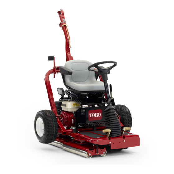
Toro GreensPro 1260 Operator's Manual
Greens roller
Hide thumbs
Also See for GreensPro 1260:
- Service manual (186 pages) ,
- Operator's manual (36 pages) ,
- Operator's manual (40 pages)

Related Manuals for Toro GreensPro 1260


Summary of Contents for Toro GreensPro 1260
- Page 1 Form No. 3429-810 Rev A GreensPro ™ 1260 Greens Roller Model No. 44913—Serial No. 404680001 and Up *3429-810* A Register at www.Toro.com. Original Instructions (EN)
- Page 2 Whenever you need service, genuine Toro parts, or additional information, contact an Authorized Service Dealer or Toro Customer Service and have the model and serial numbers of your product ready. Figure 1 identifies the location of the model and serial numbers on the product.
-
Page 3: Table Of Contents
Contents Adjusting the Parking Brake......29 Hydraulic System Maintenance ......30 Hydraulic System Safety........30 Safety ............... 4 Checking the Hydraulic Hoses and General Safety ........... 4 Fittings ............30 Safety and Instructional Decals ......4 Hydraulic Fluid Specification......31 Setup ................ -
Page 4: Safety
Safety causes distractions; otherwise, injury or property damage may occur. • Do not put your hands or feet near moving This machine has been designed in accordance with components of the machine. EN ISO 12100:2010 and ANSI B71.4-2017. • Do not operate the machine without all guards Important: For CE required regulatory data, refer and other safety protective devices in place and... - Page 5 decal133-1701 133-1701 1. Warning—read the 4. Warning—keep away Operator's Manual; do from moving parts; keep not operate the machine all guards and shields in unless you have received place. training. 2. Warning—wear hearing 5. Tipping hazard—do not protection. operate the machine near water;...
- Page 6 decal127-5884 127-5884 1. Read the Operator’s Manual. 3. 1) Push the hitch up; 2) Release the latch lever; 3) Pull the hitch down; 4) Step on the foot pedal until the hitch snaps into place; 5) Insert the lock pin. 2.
-
Page 7: Setup
Setup Loose Parts Use the chart below to verify that all parts have been shipped. Procedure Description Qty. Transport wheel Install the transport wheels. Lock bracket Bolt (M10 x 30 mm) Lock washer (M10) Washer (M10) Nut (M10) Hitch assembly Install the hitch assembly. -
Page 8: Installing The Transport Wheels
Installing the Transport Installing the Hitch Wheels Assembly Parts needed for this procedure: Parts needed for this procedure: Transport wheel Lock bracket Bolt (M10 x 30 mm) Removing the Shipping Brackets Lock washer (M10) Remove the lug nuts securing the wheel hubs to Washer (M10) the shipping bracket (Figure... - Page 9 • In the front holes, use a bolt (M10 x 100 mm), 2 washers (M10), and a locknut (M10). • In the rear holes, use a bolt (M12 x 100 mm), 2 washers (M12), and a locknut (M12). • If your machine has a third washer included with each bolt, use those washers as spacers between the hitch and the inside of the hitch pivot bracket...
-
Page 10: Removing The Machine From The Pallet
g024330 Figure 9 1. Wood blocks Place some wood boards on the ground at the end of the pallet. Note: The height of the wood boards should be g279746 Figure 8 slightly lower than the pallet. You can use pieces removed from the sides and/or ends of the crate. -
Page 11: Product Overview
Controls Product Overview Parking Brake Engage the parking brake to allow the machine to start. To engage the parking brake (Figure 12), pull back on the parking-brake lever. To disengage it, push the lever forward. g279748 Figure 10 1. Hitch-lock lever 7. -
Page 12: Engine Controls
Engine Controls time. If you press down the right pedal, the machine moves to the right, and if you press down the left Note: Refer to your engine owner’s manual for pedal, the machine moves to the left. The further you additional engine-control information. -
Page 13: Specifications
Contact your Authorized Service Dealer or authorized Toro distributor or go to www.Toro.com for a list of all approved attachments and accessories. To ensure optimum performance and continued safety certification of the machine, use only genuine Toro replacement parts and accessories. -
Page 14: Before Operation
Preparing to Use the Operation Machine Before Operation Clear any debris on top of and underneath the machine. Engaged the parking brake. Before Operation Safety Complete the following daily maintenance procedures: General Safety • Lubricating the Drive-Roller Bearing (page • Shut off the machine and wait for all movement to stop before you leave the operator’s position. -
Page 15: Filling The Fuel Tank
Filling the Fuel Tank During Operation Safety Fuel-Tank Capacity: 3.6 L (0.95 US gallons) General Safety Clean around the fuel-tank cap and remove the • The owner/operator can prevent and is responsible cap from the tank (Figure 16). for accidents that may cause personal injury or property damage. -
Page 16: Starting The Engine
The choke may not be required when starting a warm engine. • Use accessories, attachments, and replacement parts approved by The Toro® Company only. Move the throttle control to the F position. • Keep hands and feet away from the rollers. - Page 17 g279795 Figure 19 1. Locking pin 3. Hitch pedal 2. Latch g024011 Insert the locking pin through the holes in the Figure 17 latch (Figure 19). 1. Latch lever If the you are transporting the machine, connect it to the tow vehicle; refer to Connecting the Machine to the Tow Vehicle (page 17).
- Page 18 g024199 Figure 21 1. Locking pin 2. Hitch latch Lift up on the hitch assembly to tip the machine up slightly. Push down on the hitch latch to unlatch the hitch (Figure 21). Raise the hitch (Figure 22) until the latch lever locks in the slide detent (Figure 17).
-
Page 19: Operating The Machine
Operating the Machine Operating Tips • Ensure that the parking brake is engaged. When operating the machine on hills, ensure that the drive roller is on the downhill side for adequate Sit on the operator seat, taking care not to traction. -
Page 20: Maintenance
Maintenance Note: Download a free copy of the electrical or hydraulic schematic by visiting www.Toro.com and searching for your machine from the Manuals link on the home page. Maintenance Safety – Wait for all moving parts to stop. • Before you leave the operator’s position, do the –... -
Page 21: Notation For Areas Of Concern
Notation for Areas of Concern Inspection performed by: Item Date Information Daily Maintenance Checklist Duplicate this page for routine use. For the week of: Maintenance Check Item Mon. Tues. Wed. Thurs. Fri. Sat. Sun. Check that the pivot joints operate freely. Check the fuel level. -
Page 22: Pre-Maintenance Procedures
Pre-Maintenance Raising the Operator’s Seat Procedures Pull back the seat latch until it clears the seat-latch pin (Figure 23). Do not tilt the machine unless it is necessary. If you tilt the machine, engine oil could enter the cylinder head of the engine, and hydraulic fluid could leak from the cap located on top of the tank. -
Page 23: Lowering The Operator's Seat
Lowering the Operator’s Lubrication Seat Lubricating the Drive-Roller Tilt the seat down until the seat latch snaps securely over the seat-latch pin (Figure 24). Bearing Service Interval: Before each use or daily Lubricate the drive-roller bearing immediately after each washing. Grease Type: No. -
Page 24: Engine Maintenance
Engine Maintenance Engine Safety • Shut off the engine before checking the oil or adding oil to the crankcase. • Do not change the governor speed or overspeed the engine. Engine Oil Specification Type: APl service classification SL or higher g281202 Viscosity: select the oil viscosity according to Figure 27... - Page 25 Raise the machine onto the transport wheels; refer to Raising the Machine onto the Transport Wheels (page 16). Tilt the machine so that the end of the machine with the engine is closer to the ground, and support the other end of the machine to hold it in this position.
-
Page 26: Checking The Air-Filter Elements
Adding Oil to the Engine Crankcase Capacity: 0.60 L (0.63 US qt) Lower the machine onto the rollers; refer to Lower the Machine onto the Rollers (page 18). Fill the crankcase with the specified oil; refer to Engine Oil Specification (page 24) Checking the Engine-Oil Level (page 24). -
Page 27: Servicing The Air Cleaner
Servicing the Air Cleaner Inspect the gasket for wear and damage (Figure 30). Service Interval: Every 50 hours—Clean the air Replace the gasket if it is worn or damaged. cleaner (more often in dirty or dusty conditions). Ensure that the gasket is positioned on the air inlet for the carburetor (Figure 30). -
Page 28: Checking And Adjusting The Valve Clearance
Wash the sediment cup and O-ring in Service Interval: Every 300 hours nonflammable solvent, and dry them thoroughly. Important: Place the O-ring in the fuel-shutoff valve and Refer to your authorized Toro install the sediment cup (Figure 33). Tighten the distributor for service. -
Page 29: Electrical System Maintenance
If the safety-interlock system does not Adjusting the Parking Brake (page 29). operate as described below, have an authorized Toro distributor repair it immediately. Note: The engine shuts off in 1 second when you press the motion pedal with the parking If on the transport wheels, lower the machine brake engaged. -
Page 30: Hydraulic System Maintenance
Hydraulic System Maintenance Hydraulic System Safety • Seek immediate medical attention if fluid is injected into skin. Injected fluid must be surgically removed within a few hours by a doctor. • Ensure that all hydraulic-fluid hoses and lines are in good condition and all hydraulic connections and fittings are tight before applying pressure to the hydraulic system. -
Page 31: Hydraulic Fluid Specification
Note: Before working on any part of the hydraulic drive system, shut off the engine to depressurize the Alternative fluids: If the Toro fluid is not available, system. Before starting the engine after hydraulic other conventional, petroleum-based fluids may be... -
Page 32: Changing The Hydraulic Fluid And Filter
Draining the Hydraulic Fluid For example: If the fluid is at ambient-air temperature, about 24°C (75° F), fill only to the Align a drain pan with a 2 L (2 US qt) capacity cold level. If the fluid is about 65°C (150° F), fill under the hydraulic reservoir (Figure 36). - Page 33 Start the engine and run it at low idle for 3 to 5 minutes. Running the engine circulates the hydraulic fluid and removes air trapped in the hydraulic system. Check the machine for hydraulic leaks at the reservoir, hydraulic hoses, and the hydraulic filter.
-
Page 34: Chassis Maintenance
Chassis Maintenance Cleaning Checking the Tire Air Cleaning the Machine Pressure Service Interval: After each use Important: Measure the air pressure in the tires of the Do not use brackish or reclaimed transport wheels. water to clean the machine. You should measure 103 kPa (15 psi). Clean the machine with fresh water. -
Page 35: Storage
Check and tighten all bolts, nuts, and screws. Repair or replace any part that is worn or damaged. Paint all scratched or bare metal surfaces. Paint is available from your authorized Toro distributor. Preparing the Machine for Long-Term Storage More than 90 Days... - Page 36 Notes:...
- Page 37 Notes:...
- Page 38 The Way Toro Uses Information Toro may use your personal information to process warranty claims, to contact you in the event of a product recall and for any other purpose which we tell you about. Toro may share your information with Toro's affiliates, dealers or other business partners in connection with any of these activities. We will not sell your personal information to any other company.
- Page 39 While the exposure from Toro products may be negligible or well within the “no significant risk” range, out of an abundance of caution, Toro has elected to provide the Prop 65 warnings. Moreover, if Toro does not provide these warnings, it could be sued by the State of California or by private parties seeking to enforce Prop 65 and subject to substantial penalties.
- Page 40 Countries Other than the United States or Canada Customers who have purchased Toro products exported from the United States or Canada should contact their Toro Distributor (Dealer) to obtain guarantee policies for your country, province, or state. If for any reason you are dissatisfied with your Distributor's service or have difficulty obtaining guarantee information, contact your Authorized Toro Service Center.