Table of Contents
Advertisement
Quick Links
Download this manual
See also:
Product Manual
Advertisement
Table of Contents

Related Manuals for ABB i-bus EIB


Summary of Contents for ABB i-bus EIB
- Page 1 ® Product Manual ABB i-bus EIB / KNX Switch Actuator Modules for the Room Controller Online version SA/M 2.6.1 High resolution pictures deleted ES/M 2.230.1 ES/M 2.24.1 Intelligent Installation Systems...
-
Page 2: Table Of Contents
Parameter window: “General” ..........25 Operating mode: “Switch actuator” .............26 4.3.1 Parameter window: “General” ..........26 4.3.2 Parameter window: “Function” ..........27 4.3.3 Parameter window: “Time”.............28 4.3.4 Parameter window: “Presets”..........31 4.3.5 Parameter window: “Scene”...........32 4.3.6 Parameter window: “Logic” ............33 © 2004 ABB STOTZ-KONTAKT GmbH... - Page 3 Despite checking that the contents of this document match the hardware and software, deviations cannot be completely excluded. We therefore cannot accept any liability for this. Any necessary corrections will be inserted in new versions of the manual. Please inform us of any suggested improvements. © 2004 ABB STOTZ-KONTAKT GmbH...
-
Page 4: General
SA/M 2.6.1 signaling equipment (ohmic loads) ES/M 2.230.1, ES/M 2.24.1 The Room Controller Basis Device establishes the connection to the ABB i- ® EIB / KNX installation bus. All the modules have two outputs each. The Switch Actuator Module SA/M 2.6.1 switches via relay outputs while the Electronic Switch Actuator... -
Page 5: Device Technology
– Housing, colour Plastic housing, anthracite, halogen-free – Housing dimensions (WxHxD) 49 mm x 42 mm x 93 mm – Weight 0.1 kg – in accordance with the EMC guideline and CE norm the low voltage guideline © 2004 ABB STOTZ-KONTAKT GmbH... -
Page 6: Circuit Diagram
2.1.4 Assembly and installation The device is solely intended for operation in the Room Controller Basis Device. It can be snapped into any module slot. The mounting position can be selected as required. © 2004 ABB STOTZ-KONTAKT GmbH... -
Page 7: Es/M 2.230.1 Electr. Switch Actuator Module, 2-Fold, 230 V
– Housing, colour Plastic housing, anthracite, halogen-free – Housing dimensions (WxHxD) 49 mm x 42 mm x 93 mm – Weight 0.08 kg – in accordance with the EMC guideline and CE norm the low voltage guideline © 2004 ABB STOTZ-KONTAKT GmbH... -
Page 8: Circuit Diagram
2.2.4 Assembly and installation The device is solely intended for operation in the Room Controller Basis Device. It can be snapped into any module slot. The mounting position can be selected as required. © 2004 ABB STOTZ-KONTAKT GmbH... -
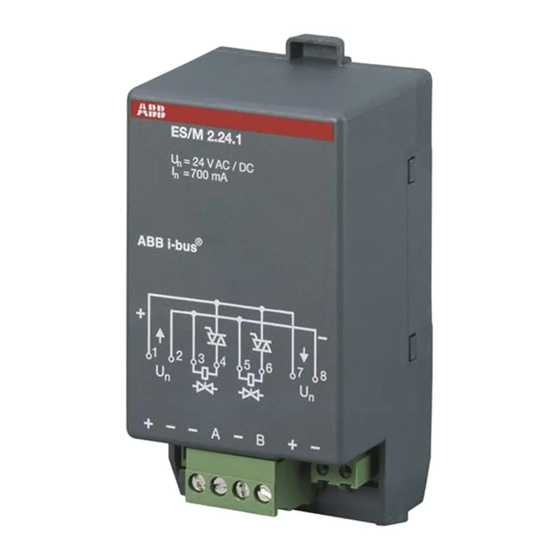
Page 9: Technical Data
– Housing, colour Plastic housing, anthracite, halogen-free – Housing dimensions (WxHxD) 49 mm x 42 mm x 93 mm – Weight 0.08 kg – in accordance with the EMC guideline and CE norm the low voltage guideline © 2004 ABB STOTZ-KONTAKT GmbH... -
Page 10: Circuit Diagram
“+” and “–“. 2.3.4 Assembly and installation The device is solely intended for operation in the Room Controller Basis Device. It can be snapped into any module slot. The mounting position can be selected as required. © 2004 ABB STOTZ-KONTAKT GmbH... -
Page 11: Application And Planning
Several outputs are required for control and the output therefore controls further outputs (“Slaves”) as a “Master” via the bus. The master-output itself controls fan speed 1. See under section 3.4 for further explanations. © 2004 ABB STOTZ-KONTAKT GmbH... -
Page 12: Operating Mode: "Switch Actuator
If the device receives a further ON command when the staircase lighting is switched on, the staircase lighting time is added to the remaining period. In this case, the time does not restart (no retrigger). Application: Lighting control on staircases, monitoring of telegrams © 2004 ABB STOTZ-KONTAKT GmbH... -
Page 13: Logic
Output Object “Logical connection 2” First, the object “Switch” is evaluated together with the object “Logical connection 1”. The result is linked with the object “Logical connection 2”. The following logic functions are possible: © 2004 ABB STOTZ-KONTAKT GmbH... -
Page 14: Presets
Actuator 2 Actuator 3 Fig. 1: Controlling light scenes via presets Switching states (“preset values”) can be retrieved via the object “Call preset …”. A maximum of 4 preset values are available for each output: © 2004 ABB STOTZ-KONTAKT GmbH... - Page 15 The following diagram clarifies this: Actuator 1 Actuator 2 Actuator 3 Old state Retrieve preset (e.g. preset2) Restore old state (e.g. preset1) Fig. 3: Restoring the old brightness state (example) © 2004 ABB STOTZ-KONTAKT GmbH...
-
Page 16: 8-Bit Scene
The threshold values can be interpreted as hysteresis values: Threshold values are hysteresis values Object “Threshold value” Upper threshold Lower threshold Output When the value exceeds the upper threshold or falls below the lower threshold, the output is switched. © 2004 ABB STOTZ-KONTAKT GmbH... - Page 17 When the value exceeds or falls below any threshold value, the output is switched. Note: If the object “Threshold value” receives a value which does not exceed or fall below any of the threshold values compared to the old value, no switching operations are triggered. © 2004 ABB STOTZ-KONTAKT GmbH...
-
Page 18: Function Diagram
The result is analysed by the time function; when the staircase lighting function is active, this can result in the staircase lighting being switched on. The forced operation has the highest priority as it is evaluated last of all the functions. © 2004 ABB STOTZ-KONTAKT GmbH... -
Page 19: Operating Mode: "Heating Actuator
Important: A pulse width modulation leads to frequent switching of the outputs. Consider the limited number of switching cycles for standard switch actuators! The use of electronic switch actuators is preferable in each case. © 2004 ABB STOTZ-KONTAKT GmbH... - Page 20 Is fault Trigger safety mode position active? Type of 1 bit 1 byte control Output follows Control acc. to object “Switch” object “Control value (PWM)” Fig. 7: Prioriy of the special functions (flow chart) © 2004 ABB STOTZ-KONTAKT GmbH...
-
Page 21: Operating Mode: "Fan Coil Control
The fan is driven by a motor. The motor and the valves are regulated by the Fan Coil Controller FC/S 1.1. The condensed water that is generated by the cooling process is collected in a drip tray. © 2004 ABB STOTZ-KONTAKT GmbH... -
Page 22: Variants
Output A = Master Room Controller Fan motor SA/M 2.6.1 SA/M 2.6.1 Stufe 1 Stufe 2 Stufe 3 SA/M 2.6.1 Valve (Heating) Valve SA/M 2.6.1 (Cooling) Fig. 11: Connection of a fan coil unit (example) © 2004 ABB STOTZ-KONTAKT GmbH... - Page 23 If the fan coil is only either cooling or heating (2-pipe-version), only one valve is required and two switch actuator modules are sufficient. When using electrothermal valve drives for valve control, the use of Electronic Switch Actuator Modules (ES/M) is recommended. © 2004 ABB STOTZ-KONTAKT GmbH...
-
Page 24: Reaction On Voltage Failure And Recovery
The behaviour of the outputs is identical to the behaviour on recovery of the bus voltage. It can be parameterised for each output (except for fan coil control). Reaction after programming After programming, the device behaves in the same way as after bus voltage recovery (parameterisable). © 2004 ABB STOTZ-KONTAKT GmbH... -
Page 25: Project Design And Programming
The function of the output can be selected here. The options available are “Switch actuator”, “Heating actuator” and “Fan coil control”. The other parameters are dependent on the selected operating mode. See under section 3.1 for further explanations about the operating modes. © 2004 ABB STOTZ-KONTAKT GmbH... -
Page 26: Operating Mode: "Switch Actuator
In the setting “unchanged”, the state of the output does not change. On bus voltage recovery, the output is set once the parameterised initialisation time of the Room Controller has elapsed. © 2004 ABB STOTZ-KONTAKT GmbH... -
Page 27: Parameter Window: "Function
Parameter: “Enable function ‘priority/forced operation, cyclic monitoring’” This parameter enables the safety functions “Cyclic monitoring, forced operation” (parameter window “A: Safety”). Parameter: “Enable threshold function” This parameter enables the ‘Threshold value function” (parameter window “A: Threshold”). © 2004 ABB STOTZ-KONTAKT GmbH... -
Page 28: Parameter Window: "Time
Note: If the parameter value is “yes”, the staircase lighting can also be switched off via the following other objects, if they lead to a disconnection: “Logical connection”, “Preset”, “Lightscene”, “Disable”, “Permanent ON”, “Forced operation”. © 2004 ABB STOTZ-KONTAKT GmbH... - Page 29 Parameter: “Switch ON delay” This parameter sets the delay for switching on the output after an ON command. Parameter: “Switch OFF delay” This parameter sets the delay for switching off the output after an OFF command. © 2004 ABB STOTZ-KONTAKT GmbH...
- Page 30 Parameter: “Limited number of ON impulses” The number of flashing pulses can be limited here. After the output has been switched on and off for an adjustable “Number of ON impulses”, it will be switched off permanently. © 2004 ABB STOTZ-KONTAKT GmbH...
-
Page 31: Parameter Window: "Presets
Telegram value “0” saves preset1 while telegram value “1” stores preset2. If the special function “restore old value before preset2” or “restore parameterised value of preset2” has been assigned to preset1, the telegram value “0” is ignored. © 2004 ABB STOTZ-KONTAKT GmbH... -
Page 32: Parameter Window: "Scene
After programming or after a supply voltage failure, the value that is parameterised here is restored. Note: When a scene is retrieved - the time functions are restarted - the logic operations are re-evaluated © 2004 ABB STOTZ-KONTAKT GmbH... -
Page 33: Parameter Window: "Logic
“Switch” are ignored. Parameter: “Object value after bus voltage recovery” This parameter defines which value is assigned to the object “Logical connection 1” or “Logical connection 2” on bus voltage recovery. © 2004 ABB STOTZ-KONTAKT GmbH... -
Page 34: Parameter Window: "Safety
The cyclic monitoring of the object “Switch” can be enabled here. If the device does not receive any telegrams via the object “Switch” for an adjustable period, the output is set to the safety position. The telegram value can be “0” or “1”. © 2004 ABB STOTZ-KONTAKT GmbH... - Page 35 The safety position is automatically cancelled as soon as the device receives a telegram at the object “Switch” again. Parameter: “Cyclic monitoring time” The monitoring time with which the object “Switch” is observed is set here. © 2004 ABB STOTZ-KONTAKT GmbH...
-
Page 36: Parameter Window: "Threshold
Parameter: “Object value >= upper threshold” These parameters are visible if the threshold values are not hysteresis limits. They define the reaction dependent on the threshold value. The possible reaction of the output is: ON, OFF, no reaction © 2004 ABB STOTZ-KONTAKT GmbH... - Page 37 “Threshold value” exceeds or falls below the upper or lower threshold. A reaction only occurs if the object value was previously smaller or larger than the lower or upper threshold value. Further explanations can be found in section 3.2.5. © 2004 ABB STOTZ-KONTAKT GmbH...
-
Page 38: Communication Objects
Integrates the actuator in a scene. The object value contains a scene number as well as the instruction as to whether a scene should be retrieved or the current output state should be stored as a new scene value. © 2004 ABB STOTZ-KONTAKT GmbH... - Page 39 “yes”. It is sent when there is a change in the value. Note: This object may have a wrong value after supply voltage failure, if the output is parameterized to “unchanged” after bus voltage failure as well as after bus voltage recovery. © 2004 ABB STOTZ-KONTAKT GmbH...
- Page 40 Telegram value “0” stores preset1, telegram value “1” stores preset2. If the special function “restore old value before preset2” or “restore parameterised value of preset2” is assigned to preset1, the telegram value “0” is ignored. © 2004 ABB STOTZ-KONTAKT GmbH...
- Page 41 The object is visible if the parameter “Enable function ‘forced operation’” is set to “yes, via 2-bit object”. Telegram value “0”, “1” Forced operation cancelled “2” Switch off positively “3” Switch on positively © 2004 ABB STOTZ-KONTAKT GmbH...
- Page 42 The output can receive a value via this object. If this value falls below or exceeds a parameterisable threshold value, a switching operation can be carried out. A 1-byte integer value and a 2-byte floating point value are possible as data types (can be set in the parameters). © 2004 ABB STOTZ-KONTAKT GmbH...
-
Page 43: Operating Mode: "Heating Actuator
This process is also known as “continuous-action control”. The valve is closed at 0% and fully opened at 100%. The heating actuator controls intermediate values via pulse width modulation (see diagram above). © 2004 ABB STOTZ-KONTAKT GmbH... - Page 44 This parameter sets how the valve drive is triggered after bus voltage recovery until the first switching or positioning command is received from the room thermostat. The parameterised value is set as the PWM cycle time. © 2004 ABB STOTZ-KONTAKT GmbH...
-
Page 45: Parameter Window: "Function
The forced operation of the output can be enabled here in order to move the outputs to a specific position e.g. for inspection purposes. Parameter: “Enable function ‘valve purge’” The cyclic valve purge can be enabled here to prevent deposits from forming in the valves. © 2004 ABB STOTZ-KONTAKT GmbH... -
Page 46: Parameter Window: "Monitoring
“PWM cycle time for continuous control”. Parameter: “Enable object ‘Telegr. fault’” The object “Telegr. fault thermostat” which can display the failure of the room thermostat can be enabled in this parameter. © 2004 ABB STOTZ-KONTAKT GmbH... -
Page 47: Parameter Window: "Forced Operation
The valve position triggered by the actuator during the forced operation is defined in this parameter. The switch cycle time t of the control is defined in the parameter “PWM cycle time for continuous control”. © 2004 ABB STOTZ-KONTAKT GmbH... -
Page 48: Parameter Window: "Valve Purge
If “yes” is entered in this parameter, the valve is automatically purged at adjustable intervals. Parameter: “Period between valve purges” This parameter is visible for automatic valve purging. It defines the interval between two valve purges. © 2004 ABB STOTZ-KONTAKT GmbH... -
Page 49: Communication Objects
8-bit object e.g. within continuous-action control. The object value [0..255] determines the control ratio (“interpulse period”) of the valve. The valve is closed at object value 0 and fully opened at object value 255. Telegram value “0” Valve closed “255” Valve fully opened © 2004 ABB STOTZ-KONTAKT GmbH... - Page 50 Not used, always “0” Not used, always “0” Supply voltage available 7 (MSB) Type of supply voltage: 0 = AC; 1 = DC A detailed table to classify the object value can be found in section 5.1. © 2004 ABB STOTZ-KONTAKT GmbH...
-
Page 51: Operating Mode: "Fan Coil Control
With a 2-pipe system, only hot or cold water flows through the fan coil unit. The device therefore only has one heat exchanger. 4-pipe system In a 4-pipe system, the fan coil unit has separate connections for hot and cold water. The device thus has two heat exchangers. © 2004 ABB STOTZ-KONTAKT GmbH... -
Page 52: Parameter Window: "General
A two-pipe system can be used for “heating”, “cooling” or both “heating and cooling”. In latter case the object "Toggle heating/cooling" is released, over which the building control indicates whether hot or cold water is fed. © 2004 ABB STOTZ-KONTAKT GmbH... - Page 53 ® ABB i-bus EIB / KNX Project design and programming Parameter: “Function of object ‘Toggle heating/cooling’” The object “Toggle heating/cooling” can be inverted via this parameter. This is preset by the room thermostat. © 2004 ABB STOTZ-KONTAKT GmbH...
-
Page 54: Parameter Window: "Speeds
Parameter: “Hysteresis between fan speeds in %” If a fan value fluctuates around a fan speed, the ventilation would be operated continually. This can be prevented by setting a hysteresis. © 2004 ABB STOTZ-KONTAKT GmbH... -
Page 55: Parameter Window: "Function
This function enables e.g. noise reduction via the bus during operation at night. Parameter: “Enable function ‘forced operation’” The forced operation of the fan speed and the valve position can be enabled here in order to move outputs into a specific position e.g. for inspection purposes. © 2004 ABB STOTZ-KONTAKT GmbH... -
Page 56: Parameter Window: "Monitoring
The parameter is visible, if a 4-pipe system is used. Parameter: “Enable object ‘Telegr. fault’” The object “Telegr. fault thermostat” which can indicate the failure of the room thermostat can be enabled in this parameter. © 2004 ABB STOTZ-KONTAKT GmbH... -
Page 57: Parameter Window: "Speed Limitation
Parameter: “Valve position during forced operation” The valve position triggered by the actuator during forced operation is defined in this parameter. The switch cycle time t of the control is defined in the parameter “PWM cycle time for continuous control”. © 2004 ABB STOTZ-KONTAKT GmbH... -
Page 58: Communication Objects
Electronic Switch Actuator Modules ES/M 2.x.1). Object for the “Slave” function Function Object name Data type Flags 0/15 Fan coil slave Output A 1 bit This object is used to control the output via the master. © 2004 ABB STOTZ-KONTAKT GmbH... - Page 59 “Slave”. As soon as the fan is running at speed 1 at least, the object value = “1”, otherwise it is “0”. Telegram value “0” Valve closed “1” Valve opened © 2004 ABB STOTZ-KONTAKT GmbH...
- Page 60 Not used, always “0” Not used, always “0” Supply voltage available 7 (MSB) Type of supply voltage: 0 = AC; 1 = DC A detailed table to classify the object value can be found in section 5.1. © 2004 ABB STOTZ-KONTAKT GmbH...
-
Page 61: Appendix
2CDG 110 002 R0011 583145 2-fold, 6 A Electr. Switch Actuator ES/M 2.230.1 2CDG 110 013 R0011 583619 Module, 2-fold, 230 V AC Electr. Switch Actuator ES/M 2.24.1 2CDG 110 014 R0011 583626 Module, 2-fold, 24 V DC © 2004 ABB STOTZ-KONTAKT GmbH... - Page 62 ⎯⎯⎯⎯⎯⎯⎯⎯⎯⎯⎯⎯⎯⎯⎯⎯⎯⎯⎯⎯⎯⎯⎯⎯⎯⎯⎯⎯⎯⎯⎯⎯⎯⎯⎯⎯⎯⎯⎯⎯⎯⎯⎯⎯⎯⎯⎯⎯⎯⎯ 2006-04-07 © 2004 ABB STOTZ-KONTAKT GmbH...