Table of Contents
Advertisement
FIELDPOINT OPERATING INSTRUCTIONS AND SPECIFICATIONS
cFP-2200/2210/2220
Intelligent Real-Time Controllers for Compact FieldPoint
3
2
1
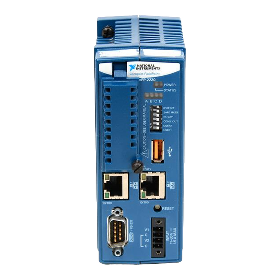
1 RS-232 Serial Port
2 RJ-45 Ethernet Port 1
3 Removable Compact Flash (cFP-2220 Only)
4 Status LED
5 Power LED
6 User-Configurable LEDs
7 DIP Switches
8 USB Port (cFP-2220 Only)
4
5
6
7
8
9
10
11
Front
9 RJ-45 Ethernet Port 2 (cFP-2220 Only)
10 Reset Button
11 Power Connector
12 Digital Input/Output Terminals (cFP-2220 Only)
13 RS-485 Serial Port (cFP-2220 Only)
14 RS-232 Serial Port (cFP-2220 Only)
15 RS-232 Serial Port (cFP-2210 and cFP-2220 Only)
Figure 1. cFP-22xx, Front and Bottom Views
12
Bottom
Bottom
13
14
15
Advertisement
Table of Contents

Related Manuals for National Instruments Fieldpoint CFP-2200


Summary of Contents for National Instruments Fieldpoint CFP-2200
- Page 1 FIELDPOINT OPERATING INSTRUCTIONS AND SPECIFICATIONS cFP-2200/2210/2220 Intelligent Real-Time Controllers for Compact FieldPoint Bottom Bottom Front 1 RS-232 Serial Port 9 RJ-45 Ethernet Port 2 (cFP-2220 Only) 2 RJ-45 Ethernet Port 1 10 Reset Button 3 Removable Compact Flash (cFP-2220 Only) 11 Power Connector 4 Status LED 12 Digital Input/Output Terminals (cFP-2220 Only)
- Page 2 This document describes how to mount the cFP-2200/2210/2220 controllers, how to connect the controllers to networks, and how to use the features of the controllers. This document also contains specifications for the controllers. In this document, the cFP-2200/2210/2220 controllers are referred to inclusively as the cFP-22xx. What You Need to Install the cFP-22xx ❑...
- Page 3 Your installation must meet the following requirements for space and cabling clearance: • Allow at least 51 mm (2 in.) all around the backplane for air circulation. • Allow 38 mm (1.5 in.) below and 51 mm (2 in.) above the controller. © National Instruments Corporation cFP-2200/2210/2220...
- Page 4 Cabling Clearance 4 slots = 246 mm (9.68 in.) 8 slots = 441 mm (17.4 in.) Cooling Outline 51 mm (2 in.) Cooling Outline 51 mm (2 in.) Figure 3. cFP-22xx Installed on cFP-BP-x, Bottom View with Dimensions 4 slots = 246 mm (9.68 in.) 8 slots = 441 mm (17.4 in.) Cabling Clearance Cooling Outline 51 mm (2 in.) All Around...
- Page 5 127.00 mm (2.5 in.) (5.0 in.) 22.19 mm (0.9 in.) 245.87 mm (9.6 in.) Figure 6. cFP-BP-4, Back View with Dimensions Make sure that no I/O modules are in the backplane before mounting it. Caution © National Instruments Corporation cFP-2200/2210/2220...
- Page 6 Mounting the Backplane on a DIN Rail The DIN rail mounting kit is NI part number 778614-01. You need one kit to mount the cFP-BP-4 on a standard 35 mm DIN rail. Complete the following steps to mount the backplane on a DIN rail. Fasten the DIN rail clip to the cFP-BP-4 using a number 2 Phillips screwdriver and the 8-32 ×...
- Page 7 You must use these screws because they are the correct depth and thread for the plates and backplane. T I O I N S Figure 9. Installing the Horizontal Panel-Mount Kit on the cFP-BP-4 © National Instruments Corporation cFP-2200/2210/2220...
- Page 8 102 mm (4 in.) 260 mm (10.25 in.) Figure 10. cFP-BP-4 with Horizontal Panel Mount Kit Installed, Front View with Dimensions 102 mm (4 in.) 457 mm (18 in.) Figure 11. cFP-BP-8 with Horizontal Panel-Mount Kit Installed, Front View with Dimensions T I O I N S Figure 12.
- Page 9 Bolt or screw the plates to a panel. Connect the PE ground terminal on the cFP-BP-x to safety ground. Caution Disconnect power and make sure that no I/O modules are in the backplane before removing it from the panel. © National Instruments Corporation cFP-2200/2210/2220...
- Page 10 Mounting the Backplane in a Standard 19 in. Rack The rack-mount kit for Compact FieldPoint is NI part number 778615-01. The following figure shows the dimensions of the rack-mount kit. 374.65 mm (14.750 in.) 278.89 mm (10.980 in.) 2× 8× Diameter 177.8 mm 38.1 mm 34.93 mm...
- Page 11 T IO IN S Figure 16. Installing the Rack-Mount Bracket on the cFP-BP-4 T IO IN S Figure 17. Installing the Rack-Mount Bracket on the cFP-BP-8 © National Instruments Corporation cFP-2200/2210/2220...
- Page 12 Bolt the rack-mount bracket to a standard 19 in. rack. Connect the PE ground terminal on the cFP-BP-x to safety ground. Disconnect power and make sure that no I/O modules are in the backplane before Caution removing it from the rack. You can install an 8 in.
- Page 13 Figure 19. Installing the Controller on the Backplane Using a number 2 Phillips screwdriver with a shank of at least 64 mm (2.5 in.) length, tighten the captive screws to 1.1 N · m (10 lb · in.) of torque. © National Instruments Corporation cFP-2200/2210/2220...
- Page 14 Installing I/O Modules on the Backplane Align the captive screws on the I/O module with the holes on the backplane. Press firmly to seat the I/O module on the backplane. Using a number 2 Phillips screwdriver with a shank of at least 64 mm (2.5 in.) length, tighten the captive screws to 1.1 N ·...
- Page 15 Hazardous voltage wiring should be performed by qualified personnel and in Caution accordance with local electrical standards. Align the captive screws on the connector block with the holes on the backplane. Press firmly to seat the connector block on the backplane. © National Instruments Corporation cFP-2200/2210/2220...
- Page 16 Figure 21. Installing a Connector Block on the Backplane Using a number 2 Phillips screwdriver with a shank of at least 64 mm (2.5 in.) length, tighten the captive screws to 1.1 N · m (10 lb · in.) of torque.
- Page 17 You can use Ethernet port 2 to connect the cFP-2220 to another system on a private network. You must first configure the second system with a static IP address in MAX. For information about using Ethernet port 2, go to and enter the infocode ni.com/info dualenet © National Instruments Corporation cFP-2200/2210/2220...
- Page 18 Wiring Power to the cFP-22xx The cFP-22xx requires an external power supply that meets the specifications in the Power Requirements section. The cFP-22xx filters and regulates the supplied power and provides power for all of the I/O modules. You must connect a power supply to at least one pair of V and C terminals. Optionally, you can connect a power supply to the other pair of V and C terminals.
- Page 19 It does not draw power from both terminals. The controller switches between V1 and V2 without affecting operation. If the output voltages of the two power supplies are within 0.1–0.6 V of each other, the cFP-22xx can use either supply. © National Instruments Corporation cFP-2200/2210/2220...
- Page 20 The controller indicates which terminal it is using on the channel called Power Note Source in software. A value of 0 indicates V2, and a value of 1 indicates V1. This behavior is different from that of older Compact FieldPoint controllers. If your application uses input from the Power Source channel, you must change your application to reflect the change in channel behavior.
- Page 21 COM 3 is an RS-232 DTE serial port with a 10-position modular jack. The Serial VIs access COM 3 as port 2. Refer to Figure 26 and Table 2 for pin locations and signal descriptions. © National Instruments Corporation cFP-2200/2210/2220...
- Page 22 COM 4 (cFP-2220 Only) COM 4 is an RS-485 serial port with a 10-position modular jack. The Serial VIs access COM 4 as port 3. COM 4 has 100 V of operational isolation. Use an external RS-485 isolator if your application requires more isolation. Refer to Figure 26 and Table 2 for pin locations and signal descriptions.
- Page 23 Logic high for the DIO ports is +5 V. Logic low is 0 V. The DIO ports are not isolated and are not intended for field connections. Use them only for simple VI controls and indicators. © National Instruments Corporation cFP-2200/2210/2220...
-
Page 24: Using The Internal Real-Time Clock
You can use the two digital inputs to control the cFP system from LabVIEW. For example, one input could be a START/STOP switch, and the other could determine which of two VIs should run at startup. NI recommends connecting a single-pole single-throw (SPST) switch between the input terminal and one of the C terminals. -
Page 25: Configuring Dip Switches
USER1 Figure 29. DIP Switches All of the DIP switches are in the OFF position when the controller is shipped from National Instruments. IP RESET Switch Push the IP RESET switch to the ON position and reboot the controller to reset the IP address to . - Page 26 NO APP Switch Push the NO APP switch to the ON position to prevent a LabVIEW RT startup application from running at startup. If you want to permanently disable a LabVIEW RT application from running at startup, you must disable it in LabVIEW. To run an application at startup, push the NO APP switch to the OFF position, create an application using the LabVIEW Application Builder, and configure the application in LabVIEW to launch at startup.
-
Page 27: Using The Reset Button
This usually occurs when the controller runs out of memory. Review your RT VI and check the memory usage. Modify the VI as necessary to solve the memory usage issue. Solid The controller has detected an unrecoverable error. Please contact National Instruments. © National Instruments Corporation cFP-2200/2210/2220... -
Page 28: Power Led
POWER LED The POWER LED is lit while the cFP-22xx is powered on. This LED indicates that the power supply connected to the controller is adequate. The POWER LED lights green when the controller is using the primary power supply and amber when the controller is using the secondary power supply. User-Configurable LEDs You can use the FieldPoint Write VI to write values to LEDs A, B, C, and D. - Page 29 If the controller is restored to the factory network settings, the LabVIEW run-time Note engine does not load. You must reconfigure the network settings and restart the controller for the LabVIEW run-time engine to load. © National Instruments Corporation cFP-2200/2210/2220...
-
Page 30: Troubleshooting
Troubleshooting This section contains troubleshooting instructions for the cFP-22xx and FieldPoint software. For more troubleshooting information, refer to the Measurement & Automation Explorer Help for FieldPoint and the Measurement & Automation Explorer Remote Systems Help. Runaway Startup Application If a runaway startup application causes the cFP-22xx to become unresponsive, you must power down the cFP-22xx, then reboot it with either the NO APP switch or the SAFE MODE switch in the ON position. -
Page 31: Specifications
Real-Time Module and the operating system, go to ni.com/info enter rdfpec Serial Ports cFP-2200 ..........One RS-232 serial port cFP-2210 ..........Two RS-232 serial ports cFP-2220 ..........Three RS-232 serial ports; one RS-485 serial port © National Instruments Corporation cFP-2200/2210/2220... -
Page 32: Power Requirements
RS-232 (DTE) serial ports Maximum baud rate......115,200 bps Data bits...........5, 6, 7, 8 Stop bits ...........1, 1.5, 2 Parity..........Odd, Even, Mark, Space Flow control........RTS/CTS, XON/XOFF, DTR/DSR RS-485 (DTE) serial port Baud rate..........9,600 to 115,200 bps Data bits...........5, 6, 7, 8 Stop bits ...........1, 1.5, 2 Parity..........Odd, Even, Mark, Space Flow control........XON/XOFF... -
Page 33: Physical Characteristics
UL 61010-1, CSA 61010-1 Note For UL and other safety certifications, refer to the product label or visit ni.com/ , search by model number or product line, and click the appropriate link certification in the Certification column. © National Instruments Corporation cFP-2200/2210/2220... -
Page 34: Electromagnetic Compatibility
Waste Electrical and Electronic Equipment (WEEE) At the end of their life cycle, all products must be sent to a WEEE recycling EU Customers center. For more information about WEEE recycling centers and National Instruments WEEE initiatives, visit ni.com/environment/weee.htm RoHS... -
Page 35: Shock And Vibration
Some products are Lloyd’s Register (LR) Type Approved for marine applications. To verify Lloyd’s Register certification, visit ni.com/ and search for the LR certificate, or look for the Lloyd’s certification Register mark on the product. © National Instruments Corporation cFP-2200/2210/2220... - Page 36 Cabling Table 4 shows the standard Ethernet cable wiring connections for both normal and crossover cables. Table 4. Ethernet Cable Wiring Connections Connector 2 Connector 2 Connector 1 (Normal) (Crossover) white/orange white/orange white/green orange orange green white/green white/green white/orange blue blue blue white/blue...
-
Page 37: Where To Go For Support
Where to Go for Support The National Instruments Web site is your complete resource for technical support. At you have access to everything from ni.com/support troubleshooting and application development self-help resources to email and phone assistance from NI Application Engineers. - Page 38 Instruments trademarks. Other product and company names mentioned herein are trademarks or trade names of their respective companies. For patents covering National Instruments products, refer to the appropriate location: Help»Patents in your software, the patents.txt file on your CD, or ni.com/patents.
Need help?
Do you have a question about the Fieldpoint CFP-2200 and is the answer not in the manual?
Questions and answers