Table of Contents
Advertisement
Quick Links
USER MANUAL AND SPECIFICATIONS
NI cRIO-9075/9076
Reconfigurable Embedded Chassis with Integrated Intelligent Real-
Time Controller for CompactRIO
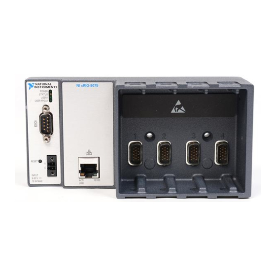
1. LEDs
2. RJ-45 Ethernet Port
3. USB Port (cRIO-9076 Only)
This document describes how to connect the cRIO-9075/9076 to a network and how to use the
features of the cRIO-9075/9076.
Safety Guidelines
Operate the cRIO-9075/9076 only as described in this document.
Figure 1. CompactRIO cRIO-9075/9076
6
5
4
1
x
3
2
4. Power Connector
5. Reset Button
6. RS-232 Serial Port
Advertisement
Table of Contents

Related Manuals for National Instruments cRIO-9075


Summary of Contents for National Instruments cRIO-9075
- Page 1 5. Reset Button 3. USB Port (cRIO-9076 Only) 6. RS-232 Serial Port This document describes how to connect the cRIO-9075/9076 to a network and how to use the features of the cRIO-9075/9076. Safety Guidelines Operate the cRIO-9075/9076 only as described in this document.
-
Page 2: Safety Guidelines For Hazardous Locations
NI for repair. Safety Guidelines for Hazardous Locations The cRIO-9075/9076 is suitable for use in Class I, Division 2, Groups A, B, C, D, T4 hazardous locations; Class I, Zone 2, AEx nA IIC T4 and Ex nA IIC T4 hazardous locations;... -
Page 3: Electromagnetic Compatibility Guidelines
A number 2 Phillips screwdriver • Power supply • Ethernet cable Note Visit ni.com/info and enter the Info Code rdsoftwareversion determine which software you need to use the cRIO-9075/9076. NI cRIO-9075/9076 User Manual and Specifications | © National Instruments | 3... -
Page 4: Mounting The Compactrio Reconfigurable Embedded Chassis
1. Measure ambient temperature here. 2. Chassis Grounding Screw Note Go to ni.com/info and enter the Info Code to find the minimum rdcrioconn cabling clearance for C Series modules with other connector types. 4 | ni.com | NI cRIO-9075/9076 User Manual and Specifications... - Page 5 You will be unable to read the serial number after you have mounted the chassis. Caution Make sure that no I/O modules are in the chassis before mounting it. NI cRIO-9075/9076 User Manual and Specifications | © National Instruments | 5...
-
Page 6: Mounting The Chassis On A Panel
Mounting the Chassis on a Panel Panel or wall mounting is the best method for applications that are subject to high shock and vibration. You can use the NI 9904 panel mount kit to mount the cRIO-9075/9076 on a flat surface. Complete the following steps. - Page 7 M4 × 25 screws. NI provides these screws with the DIN rail mount kit. Tighten the screws to a maximum torque of 1.3 N · m (11.5 lb · in.). NI cRIO-9075/9076 User Manual and Specifications | © National Instruments | 7...
- Page 8 Figure 8. Installing the DIN Rail Clip on the cRIO-9075/9076 Insert one edge of the DIN rail into the deeper opening of the DIN rail clip. Figure 9. One Edge of the DIN Rail Inserted in a Clip 1. DIN Rail Clip 2.
-
Page 9: Installing C Series I/O Modules In The Chassis
I/O modules. Align the I/O module with an I/O module slot in the chassis. The module slots are labeled 1 to 4, left to right. NI cRIO-9075/9076 User Manual and Specifications | © National Instruments | 9... -
Page 10: Removing I/O Modules From The Chassis
Remove the grounding screw from the grounding terminal on the right side of the chassis. Attach the ring lug to the grounding terminal. Tighten the grounding screw to 0.5 N · m (4.4 lb · in.) of torque. 10 | ni.com | NI cRIO-9075/9076 User Manual and Specifications... -
Page 11: Connecting The Chassis To A Network
Power Requirements section. The cRIO-9075/9076 filters and regulates the supplied power and provides power for all of the I/O modules. The cRIO-9075/9076 has one layer of reverse- voltage protection. Complete the following steps to connect a power supply to the chassis. -
Page 12: Controller Startup Options
Autoload VI on device reboot chassis reset option. Refer to the Chassis Reset Options section for more information. To restart the cRIO-9075/9076 in safe mode, press and hold the Reset button for 5 s, then release it. The Status LED lights solid yellow, indicating that the cRIO-9075/9076 is in safe mode. -
Page 13: Chassis Reset Options
Connecting Serial Devices to the cRIO-9075/9076 The cRIO-9075/9076 has an RS-232 serial port to which you can connect devices such as displays or input devices. Use the Serial VIs to read from and write to the serial port from a LabVIEW RT application. -
Page 14: Understanding Led Indications
USER1 USER FPGA1 POWER LED The POWER LED is lit while the cRIO-9075/9076 is powered on. This LED indicates that the power supply connected to the chassis is adequate. STATUS LED The STATUS LED is off during normal operation. The cRIO-9075/9076 indicates specific... -
Page 15: Troubleshooting Network Communication
Troubleshooting Network Communication If the cRIO-9075/9076 cannot communicate with the network, you can perform the following troubleshooting steps. Hold the Reset button down for 5 s, then release it. The Status LED turns on, then starts blinking three times every few seconds. The chassis is now in safe mode with output from the serial port enabled. -
Page 16: Where To Go From Here
Press and release the Reset button to reboot the chassis. Where to Go from Here Now that you have set up the cRIO-9075/9076 and configured it on your network, you can start using it in your applications. The following figure shows the main components of the CompactRIO documentation that you may find helpful as you program and use the cRIO-9075/9076. -
Page 17: Rs-232 Serial Port
FPGA type Xilinx Spartan-6 LX 25 Number of flip-flops 30,064 Number of 6-input LUTs 15,032 Number of DSP48s Available block RAM 936 kbits Number of DMA channels NI cRIO-9075/9076 User Manual and Specifications | © National Instruments | 17... -
Page 18: Power Requirements
0.20 N · m to 0.25 N · m (1.8 lb · in. to 2.2 lb · in.) Wires per screw terminal One wire per screw terminal Ferrules 0.25 mm to 1.5 mm 18 | ni.com | NI cRIO-9075/9076 User Manual and Specifications... -
Page 19: Safety Voltages
• IEC 61010-1, EN 61010-1 • UL 61010-1, CSA 61010-1 • EN 60079-0:2012, EN 60079-15:2010 • IEC 60079-0: Ed 6, IEC 60079-15; Ed 4 NI cRIO-9075/9076 User Manual and Specifications | © National Instruments | 19... -
Page 20: Electromagnetic Compatibility
Sinusoidal (IEC 60068-2-6) 5 g, 10 Hz to 500 Hz Operating shock (IEC 60068-2-27) 30 g, 11 ms half sine; 50 g, 3 ms half sine; 18 shocks at 6 orientations 20 | ni.com | NI cRIO-9075/9076 User Manual and Specifications... -
Page 21: Environmental Management
NI products in your region, visit ni.com/environment/weee. 电子信息产品污染控制管理办法(中国 RoHS) National Instruments 符合中国电子信息产品中限制使用某些有害物 中国客户 质指令(RoHS)。关于 National Instruments 中国 RoHS 合规性信息,请登录 。(For information about China RoHS ni.com/environment/rohs_china compliance, go to ni.com/environment/rohs_china NI cRIO-9075/9076 User Manual and Specifications | © National Instruments | 21... -
Page 22: Worldwide Support And Services
CONTAINED HEREIN AND SHALL NOT BE LIABLE FOR ANY ERRORS. U.S. Government Customers: The data contained in this manual was developed at private expense and is subject to the applicable limited rights and restricted data rights as set forth in FAR 52.227-14, DFAR 252.227-7014, and DFAR 252.227-7015. © 2011—2016 National Instruments. All rights reserved. 375650D-01 Mar16...
Need help?
Do you have a question about the cRIO-9075 and is the answer not in the manual?
Questions and answers