Table of Contents
Advertisement
Quick Links
USER MANUAL AND SPECIFICATIONS
NI cRIO-9024
Intelligent Real-Time Embedded Controller for CompactRIO
This document describes how to set up and use the NI cRIO-9024 and contains specifications
for the controller.
9
8
7
6
5
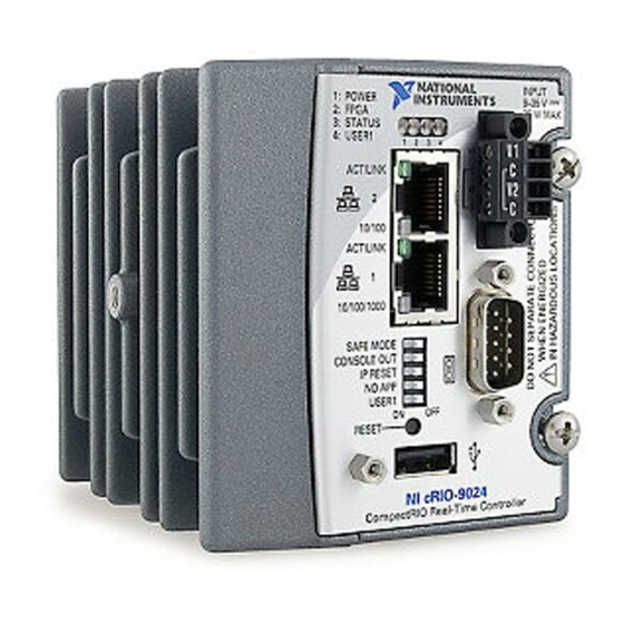
1. LEDs
2. Power Connector
3. RS-232 Serial Port
4. USB Port
5. USB Retention Standoff
Refer to the reconfigurable chassis documentation on
about the chassis. Refer to
is set up and configured. For information about software support, visit
the Info Code
swsupport
Figure 1. cRIO-9024 Front Panel
1
ni.com/gettingstarted
.
2
6. Reset Button
7. DIP Switches
8. RJ-45 Ethernet Port 1
9. RJ-45 Ethernet Port 2
ni.com/manuals
for information about using the system after it
3
4
for more information
ni.com/info
and enter
Advertisement
Table of Contents

Related Manuals for National Instruments NI cRIO-9024


Summary of Contents for National Instruments NI cRIO-9024
- Page 1 USER MANUAL AND SPECIFICATIONS NI cRIO-9024 Intelligent Real-Time Embedded Controller for CompactRIO This document describes how to set up and use the NI cRIO-9024 and contains specifications for the controller. Figure 1. cRIO-9024 Front Panel 1. LEDs 6. Reset Button 2.
-
Page 2: Safety Guidelines For Hazardous Locations
IP54 as defined in IEC/EN 60079-15. Caution The enclosure must have a door or cover accessible only by the use of a tool. 2 | ni.com | NI cRIO-9024 User Manual and Specifications... -
Page 3: Electromagnetic Compatibility Guidelines
Complete the following steps to install the cRIO-9024 on the chassis. Make sure that no power is connected to the cRIO-9024 or the chassis. Align the cRIO-9024 with the chassis as shown in the following figure. NI cRIO-9024 User Manual and Specifications | © National Instruments | 3... - Page 4 Using a Phillips #2 screwdriver, tighten the two captive screws on the front of the cRIO-9024 to 1.3 N · m (11.5 lb · in.) of torque. Dimensions The following figure shows the cRIO-9024 dimensions. 4 | ni.com | NI cRIO-9024 User Manual and Specifications...
- Page 5 Ethernet, NI recommends using a CAT-5 or better shielded twisted-pair Ethernet cable. Related Information Configuring IP Settings and Installing Software on the cRIO-9024 on page 7 Ethernet Cabling on page 18 NI cRIO-9024 User Manual and Specifications | © National Instruments | 5...
-
Page 6: Ethernet Port
Do not tighten or loosen the terminal screws on the power connector while the cRIO-9024 is powered on. Connect the primary power supply and optional secondary power supply to the power connector, as shown in the following figure. 6 | ni.com | NI cRIO-9024 User Manual and Specifications... - Page 7 If the cRIO-9024 is on a different subnet from the host computer, it does not initially appear under Remote Systems. Use the CONSOLE OUT switch to read the IP address of the cRIO-9024, and add it to Remote Systems in MAX. NI cRIO-9024 User Manual and Specifications | © National Instruments | 7...
-
Page 8: Rs-232 Serial Port
Use the Serial VIs to read from and write to the serial port. For more information about the Serial VIs, refer to the LabVIEW Help. Figure 6. Serial Port Pinout 8 | ni.com | NI cRIO-9024 User Manual and Specifications... -
Page 9: Internal Real-Time Clock
Figure 7. Controller DIP Switches SAFE MODE CONSOLE OUT IP RESET NO APP USER1 SAFE MODE Switch The following table describes the ON and OFF states of the SAFE MODE switch. NI cRIO-9024 User Manual and Specifications | © National Instruments | 9... -
Page 10: Console Out Switch
Disables console out. Keep this switch in the OFF position during normal operation. IP RESET Switch The following table describes the ON and OFF states of the IP RESET switch. 10 | ni.com | NI cRIO-9024 User Manual and Specifications... -
Page 11: No App Switch
RT Read Switch VI, refer to the LabVIEW Help. RESET Button Press the RESET button to reset the processor in the same manner as cycling power. LEDs The cRIO-9024 provides the following LEDs. NI cRIO-9024 User Manual and Specifications | © National Instruments | 11... -
Page 12: Power Led Indicators
The cRIO-9024 is in safe mode. The software has crashed twice pauses without rebooting or cycling power between crashes. Continuous blinks or The cRIO-9024 has detected an unrecoverable error. Please solid contact NI. 12 | ni.com | NI cRIO-9024 User Manual and Specifications... - Page 13 If the cRIO-9024 is restored to the factory network settings, the LabVIEW run-time engine does not load. You must reconfigure the network settings and restart the cRIO-9024 for the LabVIEW run-time engine to load. NI cRIO-9024 User Manual and Specifications | © National Instruments | 13...
-
Page 14: Specifications
For information about the life span of the nonvolatile memory and about best practices for using nonvolatile memory, go to and enter the Info ni.com/info Code SSDBP Internal RTC Accuracy 200 ppm; 35 ppm at 25 °C 14 | ni.com | NI cRIO-9024 User Manual and Specifications... -
Page 15: Power Requirements
Screw flanges provided Torque for screw flanges 0.3 N · m to 0.4 N · m (2.7 lb · in. to 3.5 lb · in.) 609 g (21.5 oz) Weight NI cRIO-9024 User Manual and Specifications | © National Instruments | 15... -
Page 16: Shock And Vibration
This category is for measurements of voltages from specially protected secondary circuits. Such voltage measurements include signal levels, special equipment, limited-energy parts of equipment, circuits powered by regulated low- voltage sources, and electronics. 16 | ni.com | NI cRIO-9024 User Manual and Specifications... -
Page 17: Safety And Hazardous Locations Standards
To obtain product certifications and the DoC for this product, visit ni.com/ certification, search by model number or product line, and click the appropriate link in the Certification column. NI cRIO-9024 User Manual and Specifications | © National Instruments | 17... -
Page 18: Environmental Management
The following table shows the standard Ethernet cable wiring connections. Table 8. Ethernet Cable Wiring Connections Connector 1 Connector 2 white/orange white/orange orange orange white/green white/green blue blue white/blue white/blue 18 | ni.com | NI cRIO-9024 User Manual and Specifications... -
Page 19: Worldwide Support And Services
States, create your service request at ni.com/support or dial 1 866 ASK MYNI (275 6964). For telephone support outside the United States, visit the Worldwide Offices section of ni.com/ NI cRIO-9024 User Manual and Specifications | © National Instruments | 19... - Page 20 CONTAINED HEREIN AND SHALL NOT BE LIABLE FOR ANY ERRORS. U.S. Government Customers: The data contained in this manual was developed at private expense and is subject to the applicable limited rights and restricted data rights as set forth in FAR 52.227-14, DFAR 252.227-7014, and DFAR 252.227-7015. © 2009—2015 National Instruments. All rights reserved. 375233F-01 Oct15...
Need help?
Do you have a question about the NI cRIO-9024 and is the answer not in the manual?
Questions and answers