Table of Contents
Advertisement
Quick Links
USER MANUAL
NI cRIO-9064
Embedded Real-Time Controller with Reconfigurable FPGA for
C Series Modules
This document describes the features of the NI cRIO-9064 and contains information about
mounting and operating the device.
RJ-45
Ethernet1
RJ-45
Ethernet2
USB 2.0 Host Port
USB 2.0 Device Port
NI cRIO-9064
Contents
Configuring the cRIO-9064...................................................................................................... 2
Configuring Startup Options............................................................................................. 3
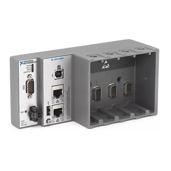
cRIO-9064 Features.................................................................................................................. 4
Ports and Connectors........................................................................................................ 4
Buttons.............................................................................................................................. 9
LEDs................................................................................................................................11
Chassis Grounding Screw............................................................................................... 13
Internal Real-Time Clock................................................................................................14
Battery............................................................................................................................. 14
File System......................................................................................................................14
RGMII
GigE
Xilinx Zynq-7000
MAC/PHY
All-Programmable SoC
RGMII
GigE
MAC/PHY
ONFI
XC7Z020
+
+
+
+
1 GB
NAND Flash
512 MB
DDR3
RS-232 Serial Port
Hardware
Data
Advertisement
Table of Contents

Related Manuals for National Instruments cRIO-9064


Summary of Contents for National Instruments cRIO-9064
-
Page 1: Table Of Contents
USER MANUAL NI cRIO-9064 Embedded Real-Time Controller with Reconfigurable FPGA for C Series Modules This document describes the features of the NI cRIO-9064 and contains information about mounting and operating the device. RGMII ONFI 1 GB RJ-45 GigE Xilinx Zynq-7000... -
Page 2: Configuring The Crio-9064
Worldwide Support and Services.................... 25 Configuring the cRIO-9064 You can connect the cRIO-9064 to a host computer or network and configure the startup options using the USB device port or the RJ-45 Gigabit Ethernet port 1. Refer to the getting started guide on ni.com/manuals... -
Page 3: Configuring Startup Options
Table 1. cRIO-9064 Startup Options Startup Option Description Force Safe Mode Rebooting the cRIO-9064 with this setting on starts the cRIO-9064 without launching LabVIEW Real-Time or any startup applications. In safe mode, the cRIO-9064 launches only the services necessary for updating configuration and installing software. -
Page 4: Crio-9064 Features
Info Code openssh more information about SSH. LabVIEW Rebooting the cRIO-9064 with this setting on enables you to add the Project Access target to a LabVIEW project. cRIO-9064 Features The cRIO-9064 provides the following features. Ports and Connectors The cRIO-9064 provides the following ports and connectors. - Page 5 3. RJ-45 Ethernet Port 2 6. Power Connector RJ-45 Gigabit Ethernet Ports The cRIO-9064 has two tri-speed RJ-45 Gigabit Ethernet ports. By default, both Ethernet ports are enabled and configured to obtain an IP address automatically. The Ethernet ports can be configured in MAX.
- Page 6 Related Information Ethernet LED Indicators on page 13 Power Connector The cRIO-9064 has a power connector to which you can connect a power supply. The following table shows the pinout for the power connector. Table 4. Power Connector Pinout Pinout...
- Page 7 11 RS-232 Serial Port The cRIO-9064 has an RS-232 serial port to which you can connect devices such as displays or input devices. Use the Serial VIs to read from and write to the serial port. Refer to the LabVIEW Help for information about the Serial VIs.
- Page 8 182238-02 182238-04 USB Host Ports The USB host ports on the cRIO-9064 support common USB mass-storage devices such as USB Flash drives, USB-to-IDE adapters, keyboards, mice, and USB cameras. Caution Do not hot-swap USB devices while the cRIO-9064 is in a hazardous location or connected to high voltages.
-
Page 9: Buttons
Caution Do not hot-swap USB devices while the cRIO-9064 is in a hazardous location or connected to high voltages. If the cRIO-9064 is not in a hazardous location, you can connect and disconnect USB devices without affecting operation. The following table shows the pinout for the USB device port. - Page 10 Hold the RESET button again for 5 seconds to boot the controller into safe mode, enable Console Out, and reset network adapters to default settings. System Reset The following figure shows the reset behavior of the cRIO-9064. 10 | ni.com | NI cRIO-9064 User Manual...
-
Page 11: Leds
Figure 4. cRIO-9064 LEDs 1. POWER LED 4. USER FPGA1 LED 2. STATUS LED 5. RJ-45 Ethernet LEDs 3. USER1 LED POWER LED Indicators The following table lists the POWER LED indicators. NI cRIO-9064 User Manual | © National Instruments | 11... - Page 12 Table 12. STATUS LED Indicators LED Pattern Indication Blinks twice and The cRIO-9064 is in safe mode. Software is not installed, which is the pauses factory default state, or software has been improperly installed on the cRIO-9064. An error can occur when an attempt to upgrade the software is interrupted.
-
Page 13: Chassis Grounding Screw
Yellow Solid 1,000 Mbit/s data rate selected Green Solid 100 Mbit/s data rate selected — 10 Mbit/s data rate selected Chassis Grounding Screw The cRIO-9064 provides a chassis grounding screw. NI cRIO-9064 User Manual | © National Instruments | 13... -
Page 14: Internal Real-Time Clock
The cRIO-9064 contains a lithium cell battery that stores the system clock information when the cRIO-9064 is powered off. There is only a slight drain on the battery when power is applied to the cRIO-9064 power connector. The rate at which the battery drains when power is disconnected depends on the ambient storage temperature. -
Page 15: Mounting The Device
You can also mount the cRIO-9064 in other orientations, on a nonmetallic surface, on a 35-mm DIN rail, on a desktop, or in a rack. Mounting the cRIO-9064 in these or other configurations can reduce the maximum allowable ambient temperature and can affect the typical accuracy of modules in the cRIO-9064. -
Page 16: Dimensions
Mounting Requirements Your installation must meet the following requirements for cooling and cabling clearance. Allow 25.4 mm (1.00 in.) on the top and the bottom of the cRIO-9064 for air circulation, as shown in the following figure. 16 | ni.com | NI cRIO-9064 User Manual... -
Page 17: Ambient Temperature
Ambient Temperature Measure the ambient temperature at each side of the cRIO-9064, 63.5 mm (2.50 in.) from the side and 25.4 mm (1.00 in.) forward from the rear of the cRIO-9064, as shown in the following figure. NI cRIO-9064 User Manual | © National Instruments | 17... -
Page 18: Mounting The Device Directly On A Flat Surface
1. Location for measuring the ambient temperature Mounting the Device Directly on a Flat Surface For environments with high shock and vibration, NI recommends mounting the cRIO-9064 directly on a flat, rigid surface using the mounting holes in the cRIO-9064. What to Use •... -
Page 19: Mounting The Device On A Panel
Dimensions. Align the cRIO-9064 on the surface. Fasten the cRIO-9064 to the surface using the M4 or number 8 screws appropriate for the surface. Tighten the screws to a maximum torque of 1.3 N · m (11.5 lb · in.). - Page 20 Complete the following steps to mount the cRIO-9064 on a panel. Align the cRIO-9064 and the panel mounting plate. Fasten the panel mounting plate to the cRIO-9064 using the screwdriver and M5 or number 10 screws. NI provides these screws with the panel mounting kit. Tighten the screws to a maximum torque of 1.3 N ·...
-
Page 21: Mounting The Device On A Din Rail
(1.25 in.) (3.47 in.) 63.5 mm (2.50 in.) Mounting the Device on a DIN Rail You can use the NI DIN rail mounting kit to mount the cRIO-9064 on a standard 35-mm DIN rail. What to Use • cRIO-9064 •... -
Page 22: Mounting The Device On A Rack
Fasten the DIN rail kit to the cRIO-9064 using the screwdriver and M4 × 25 flathead screws. NI provides these screws with the DIN rail mounting kit. Tighten the screws to a maximum torque of 1.3 N · m (11.5 lb · in.). - Page 23 1. Desktop mounting brackets (x2) 3. M3x14 screws (x2) 2. Adapter bracket 4. M3x20 screws (x2) What to Do Complete the following steps to mount the cRIO-9064 on a desktop. NI cRIO-9064 User Manual | © National Instruments | 23...
- Page 24 Repeat steps 2 and 3 to attach the other end bracket to the other end of the chassis. Desktop Mounting Dimensions The following figures show the desktop mounting dimensions for the cRIO-9064. 24 | ni.com | NI cRIO-9064 User Manual...
-
Page 25: Worldwide Support And Services
(EMC) and product safety. You can obtain the DoC for your product by visiting ni.com/certification. If your product supports calibration, you can obtain the calibration certificate for your product at ni.com/calibration. NI cRIO-9064 User Manual | © National Instruments | 25... - Page 26 CONTAINED HEREIN AND SHALL NOT BE LIABLE FOR ANY ERRORS. U.S. Government Customers: The data contained in this manual was developed at private expense and is subject to the applicable limited rights and restricted data rights as set forth in FAR 52.227-14, DFAR 252.227-7014, and DFAR 252.227-7015. © 2016 National Instruments. All rights reserved. 376508B-01 Jun16...
Need help?
Do you have a question about the cRIO-9064 and is the answer not in the manual?
Questions and answers