Sign In
Upload
Manuals
Brands
Panasonic Manuals
Control Unit
FP-XH M8N16PD
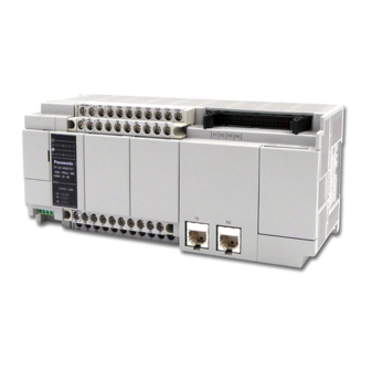
Panasonic FP-XH M8N16PD Manuals
Manuals and User Guides for Panasonic FP-XH M8N16PD. We have
1
Panasonic FP-XH M8N16PD manual available for free PDF download: User Manual
Panasonic FP-XH M8N16PD User Manual (556 pages)
Programmable controller
Brand:
Panasonic
| Category:
Control Unit
| Size: 11.99 MB
Table of Contents
Table of Contents
7
1 System Structure
23
Overview of System
24
Funcntions of Control Unit
24
Outline of Specifications
25
Unit List
26
FP-XH M8N Control Unit
26
FP-X Expansion Unit
26
FP-X Expansion FP0 Adapter
27
FP-X Add-On Cassette (Communication Cassette)
27
FP-X Add-On Cassette (Function Cassette)
27
Unit Type and Product Number
28
FP-XH M8N16PD Control Unit
28
FP-X Expansion Unit
28
FP-X Expansion FP0 Adapter
29
FP-X Add-On Cassette (Communication Cassette)
29
FP-X Add-On Cassette (Function Cassette)
29
Options
29
Repair Parts
30
Restrictions on Unit Combinations
31
Restrictions on FP-X Expansion Units
31
Restrictions on FP-X Expansion Adapter
33
Restrictions on Add-On Cassette Combination
34
Restrictions on Communication Function
36
Restrictions on Servo Amplifier
37
Restrictions on Parameter Settings
37
Combination of Parameters and Home Return Methods
38
2 Control Unit Specifications
39
Parts Name and Funcations
40
Control Unit
40
Status Indicator Leds
42
COM0 Port Specifications
43
Power Supply Specifications
44
Input / Output Specifications (General-Purpose Input/Output Part)
45
Input Specifications
45
Output Specifications
46
Input Specifications (Pulse Input Part)
47
3 I/O Allocation
49
Basic I/O Assignment
50
Counting Method of I/O Numbers
50
I/O Number Assignment Method
50
List of I/O Numbers for Units
52
FP-XH M8N Control Unit (General-Purpose I/O Part)
52
FP-XH M8N Control Unit (Motion Control Part)
53
FP-X Expansion Unit
55
FP-X Function Cassette
56
Assignment of FP0 Expansion Units
57
I/O Number Assignment Method
57
Types and I/O Numbers of FP0R Expansion Units
58
Types and I/O Numbers of FP0 Expansion Units
59
Detailed I/O Information of Motion Control Part
60
4 Installation
77
Installation
78
Installation Environment and Space
78
Backup Battery Installation
80
Add-On Cassette Installation
81
Precautions for Installing Add-On Cassettes
81
Communications Cassette Installation
81
Function Cassette Installation
82
Connecting FP-X Expansion Unit
83
Setup of Terminal Setting Switches
83
Confirmation of FP-X Expansion Cables
83
Connecting FP-X Expansion Unit
84
Connecting FP0 Expansion Unit
85
Connecting FP-X Expansion FP0 Adapter
86
Installation
87
Installation and Removal for DIN Rail
87
Mounting with Screws
88
5 Wiring of Power Supply and General-Purpose I/O Parts
89
Terminal Arrangement
90
Power Supply and General-Purpose I/O Parts
90
Wiring of Power Supply
91
General Precautions
91
Grounding
91
Power Supply of Control Unit / Expansion Unit
92
Power Supply of FP-X Expansion FP0 Adapter / FP0 Expansion Unit
94
Wiring of Input and Output
96
Precautions Regarding Input and Output Wirings
96
Input Wiring
97
Output Wiring
99
Wiring of Terminal Block
100
Suitable Wires
100
Terminal Block Cover
100
Installation and Removal of Terminal Block
101
Safety Measures
102
Momentary Power Failures
103
Watchdog Timer
103
6 Wiring of Motion I/O Parts
105
Terminal Layout Diagram
106
Settings on Servo Amplifier
107
Checking Rotary Switches
107
Connection of Limit Input and Near Home Input
108
Combination of Parameters and Home Return Methods
109
Connection of General-Purpose Monitor Input
110
Connection of RTEX Operation Output
110
Connection of Network
111
Wiring Method
111
Precautions on Wiring
111
Pulse Input Connection
112
Linear Driver Type
112
Transistor Open-Collector Type
112
Transistor Resistor Pulling up Type
112
Precautions on Wiring
114
Specifications of Scattered Cable Connectors
114
Usage of Scattered Cable Connector
115
7 Power On/Off and Check Items
117
Before Turning on the Power
118
Procedure for Turning on the Power
119
Procedure for Turning off the Power
119
Check with Power Turned on
120
Check Items after Turning Power on
120
Checking the Network Communication State
121
Checking the Safety Circuit Based on a Unit
122
Checking the Operation of Near Home Switch
123
Checking the Rotation, Movement Direction and Distance
123
8 Steps before Running
125
Before Turning on the Power
126
Check Items
126
Steps before Running
127
Offline Editing of the Program
128
Program Elements
128
Settings of the System Register
128
Setting of Position Control Parameters
129
Program Download and Run
130
Before Turning on the Power
130
Program Downloading and Mode Switching
131
Overall Program Check
135
Program Verify
135
Online Editing
137
Online Editing Summary
137
Online Editing of the Program
137
Online Editing of the System Register
139
Program Block
140
Program Block Summary
140
Change Sequence of Pbs
141
9 Setting of Position Control Parameters
144
Axis Allocation for Use
144
Settings in Configurator PM7
144
Parameter Settings
146
Parameter Settings in Configurator PM7
146
Parameter Setting Items
147
Synchronous Parameter / Cam Pattern Settings
150
Synchronization Parameter Settings
150
Cam Pattern Settings
151
Creating Positioning Data Table
152
Structure of the Position Control Data Table
152
Select Type of Position Control Data Setting Area
153
Data Table No. and Position Control Startup
154
Running Mode and Data Table
155
Saving and Managing Files
156
File Type
156
Saving Parameters as Part of Project File
156
Saving Parameters as Parameter File
157
Exporting Parameters to CSV Files
158
10 Transfer to Unit and Commissioning
159
Check on Settings
160
Data Check of Parameters
160
Comparison of Parameter Information
161
Transfer of Parameters
162
Download by FPWN GR7
162
Download by Configurator PM7
163
Monitoring on Configurator PM7
164
Status Monitor
164
Data Monitor
166
Tool Operation
168
Tool Operation Function
168
Servo ON/OFF with Tool Operation Function
169
JOG Operation with Tool Operation Function
170
Home Return by Tool Operation Function
172
Positioning by Tool Operation Function
174
Teaching by Tool Operation Function
177
Monitoring Current Value with Program
179
Current Value Area
179
Reading of the Current Value
179
11 Automatic Operation (Position Control)
181
Basic Operations
182
Position Control Method
182
Setting and Operation of E-Point Control
184
Setting and Operation of P-Point Control
185
Setting and Operation of C-Point Control
186
Setting and Operation of J-Point Control
187
Sample Program (E-Point, P-Point and C-Point Control)
189
Sample Program (J-Point Control)
190
Programming Precautions
191
Interpolation Control
192
Interpolation Control Types
192
Setting and Operation of 2-Axis Linear Interpolation
195
Setting and Operation of 2-Axis Circular Interpolation
197
Setting and Operation of 3-Axis Linear Interpolation
199
Setting and Operation of 3-Axis Spiral Interpolation
201
Positioning Repeat Function
204
Setting and Operation of Repeat Operation
207
12 Automatic Operation (Synchronous Control)
209
Synchronous Control
210
Outline of Synchronous Control
210
Settings for Master and Slave Axes
212
Selection for Master and Slave Axes
212
Selection of Slave Axes and Settings
213
Start and Cancel of Synchronous Control
214
Precautions When Canceling or Starting Synchronous Control
216
Electronic Gear Function
220
Outline of Electronic Gear Function
220
Types and Contents of Setting Parameters
221
Gear Ratio Changes While in Operation
222
Electronic Clutch Function
224
Types and Contents of Setting Parameters
225
Trigger Types for Electronic Clutch
226
Engagement Methods of Electronic Clutch
227
Phase Specification Clutch off Function
228
Electronic Cam Function
230
Outline of Electronic Cam Function
230
Types and Contents of Setting Parameters
232
Cam Pattern Setting Method
233
Rewriting Cam Patterns by Programs
240
Advance Angle Correction Function
247
13 Manual Operation (JOG Operation)
251
Setting and Operation of JOG Operation
252
Speed Change During Operation
254
14 Manual Operation (Home Return)
257
Type of Home Return
258
Setting and Operaion of Home Return
262
15 Pulse Input Function
265
Pulse Input
266
Pulse Input Application
266
Selection of Pulse Input Applications
267
Input Mode of Pulse Input
268
Monitoring of Pulse Input Values
270
Pulse Input Value Change Function
270
Setting and Operation of Pulsar
272
Overview
272
Settings for Pulsar Operation
273
Operation of Pulsar
274
Pulse Input / High-Speed Counter Function
276
Overview
276
Settings When Using High-Speed Counter
276
Count Disable/Enable Control
277
16 Stop Function
279
Types and Settings of Stop Function
280
Type of Stop Operations
280
Stop Tme Settings
281
Operation During Stop
282
Pause Function
283
Pause Settings
283
17 Auxiliary Function
285
Dwell Time
286
Software Limit
287
Auxiliary Output
288
Auxiliary Output Function
288
Auxiliary Output Settings
289
Monitoring of Auxiliary Output
290
Operation Upon Movement Change During Operation
290
Coordinate Origin
291
Current Value Update
293
Target Speed Change Function
295
Overview
295
Setting Procedures and Operations (Speed Direct Specification Method)17-12
296
Setting Procedures and Operations (Ratio Specification Method)
299
Movement Amount Change Function
301
Overview
301
Setting Procedures and Operations
302
Direct Input / Output
306
Direct Input / Output Function
306
Direct Input
308
Direct Output
309
Torque Limit
310
Monitor Error (Torque / Actual Speed Judgement)
313
Operation Done Signal
314
Operation Done Flag and Imposition Flag
314
Position Deviation Simple Monitor
315
AMP Parameter R/W Function
316
Overview
316
Reading Parameters from AMP
317
Writing Parameters to AMP
319
Saving AMP Parameters (Writing to EEPROM)
321
Resetting AMP (Restart)
323
AMP Monitoring Function
325
Overview
325
Monitoring Items
325
Monitoring Procedure
327
18 Instruction Reference
329
Motion Control Instructions
330
F384 PTBLR] Positioning Parameter Read Instruction
330
F385 PTBLW] Positioning Parameter Write Instruction
331
F386 PSET] Positioning Start Data Table Setting
332
F387 PSTRD] Axis Status Acquisition
333
F388 PERRD] Positioning Error /Warning Acquisition
335
F389 UCLR] Positioning Error / Warning Clearing
336
Direct Input Instruction
337
DST·DST/] Direct Start / Direct Start NOT
337
DAN·DAN/] Direct and /·Direct and NOT
340
DOR·DOR/] Direct or / Direct or NOT
343
Direct Output Instruction
346
DOT] Direct Output
346
DSET·DRST] Direct Set / Direct Reset
349
DKP] Direct Hold
354
19 Error/Warning Annunciation Function
357
Errors and Warnings
358
Check and Clearing with Configurator PM7
358
Check and Clearing with User Program
359
Error/Warning Log
360
Change of Error Recovery Processing
362
Outline
362
Table of Error Codes
363
AMP Errors (0001H 0- )
363
System Errors (1000H - )
370
AMP Communication Errors (2000H - )
371
Axis Operation Errors (3000H - )
372
Set Value Errors (4000H - )
374
Setting Value Errors of Synchronous Parameters (5000H - )
378
Table of Warning Codes
381
AMP Warnings (A000H - )
381
Unit Warning (B000H - )
382
20 Troubleshooting
387
Self-Diagnosis Function
388
Status Display LED of the Control Unit
388
Status Display LED of the FP-X Expansion FP0 Adapter
389
Operation Mode in Case of Exception
389
What to Do if an Error Occurs
390
ERR LED Blinking
390
When Not Switched to RUN Mode
392
When ERR.LED Lights up
392
If All Leds Are Not Lit
393
When Protection Error Message Shows
393
When the Output Is Not Normal
394
When Expansion Units Are Not Operated
395
In Case of Communication Error (RS-232C)
396
In Case of Communication Error (RS-422)
397
In Case of Communication Error (RS-484)
398
In Case of Communication Error (Ethernet)
399
What to Do if an Error Occurs
400
Cannot Communicate with AMP
400
Motor Does Not Rotate and Operate
401
21 Memory /Master Memory Cassette
403
Memory Backup
404
Program Memory Backup
404
Operation Memory Backup
404
Operation Memory Backup (When Battery Installed)
405
Alarm Battery Error / Setting of the Hold Area
406
RAM / ROM Transfer Function
408
Outline of Function
408
Operations Using Tool Software
408
Functions of Master Memory Cassette
409
Outline of Functions
409
Setting of Master Memory Unit
409
Master Memory Function
410
Outline of Function
410
Before Turning on the Power
411
Transferring Data to Master Memory Cassette
412
Transferring Data from Master Memory Cassette to Control Unit
414
Using Master Memory Cassette with Other Models
415
Clock/Calendar
416
Clock/Calendar Application Examples
417
22 Security Functions
419
Password Protection Function
420
Outline of Function
420
Tool Software Setting
420
Program Upload Protection Function
427
Outline of Function
427
Tool Software Setting
428
Security Function Applicability List
429
Control Unit
429
23 General-Purpose Input / High-Speed Counter Function
431
General-Purpose Input / High-Speed Counter Function Summary
432
High-Speed Counter Function Summary
432
Counting Range and Elapsed Value (Current Value) Area
432
When Using the High-Speed Counter Function
433
Type of Input Mode
434
Minimum Input Pulse Width
435
Settings of the System Registers
436
Settings of System Registers
436
General-Purpose Input / High-Speed Counter Related Instruction
438
F0 MV] High-Speed Counter Control Instruction
438
F1 DMV] Elapsed Value Read and Write Instruction
440
F166 HC1S] High-Speed Counter Target Value Consistent on Instruction
441
[F167 HC1R] High-Speed Counter Target Value Consistent off Instruction23-11
441
Interruption Program Startup When Target Value Has Consistent Control23-13
443
Sample Program
444
Running of the Position Control Which Has Used Inverter (1 Speed)
444
Running of the Position Control Which Has Used Inverter (2 Speed)
446
24 Other Functions
449
Analog Potentiometer
450
Outline of Function
450
Analog Potentiometer Application Examples
450
Input Time Constant Setting Function
451
Outline of Function
451
25 Maintenance and Inspection
453
Precautions for Using Backup Battery
454
Backup Battery Replacement
454
Backup Battery Lifetime and Replacement Time
455
Inspection
456
26 Specifications
457
Control Unit Specifications
458
General Specifications
458
Performance Specifications
459
Performance Specifications of Motion Control Part
461
Communication Specifications
464
Communication Specifications of Control Unit
464
Specifications of Communication Cassette
465
Operation Memory Areas
467
Positioning Memory
468
Entire Configuration of Positioning Memory
468
Common Area (Memory Area No.0)
472
Each Axis Information Area (Memory Area No. 1)
490
Each Axis Setting Area (Memory Area No. 2)
492
Cam Pattern Editing Area (Memory Area No. 3)
506
Synchronous Control Area (Memory Area No. 4)
510
Positioning Operation Change Setting Area (Memory Area No. 5)
513
AMP Parameter Control Area (Memory Area No. 6)
514
Table of System Registers
515
Table of Special Internal Relays
521
Table of Special Data Registers
534
Table of Error Codes
547
Table of Syntax Check Errors
547
Table of Self-Diagnostic Errors
548
Table of MEWTOCOL-COM Communication Errors
550
Dimensions
551
Installation Dimensions
551
Advertisement
Advertisement
Related Products
Panasonic M81X15G4Y
Panasonic M81X25G4L
Panasonic M8RX25GK4L
Panasonic M8MX25G4Y
Panasonic M81X15GV4Y
Panasonic M81X15GV4L
Panasonic M8MX25GB4Y
Panasonic M8RX25GV4Y
Panasonic M8RX25GBV4Y
Panasonic M81X25H4L
Panasonic Categories
Camcorder
Air Conditioner
TV
Digital Camera
Cordless Telephone
More Panasonic Manuals
Login
Sign In
OR
Sign in with Facebook
Sign in with Google
Upload manual
Upload from disk
Upload from URL