Sign In
Upload
Manuals
Brands
Cisco Manuals
Network Hardware
ONS 15454 SDH
Cisco ONS 15454 SDH Manuals
Manuals and User Guides for Cisco ONS 15454 SDH. We have
3
Cisco ONS 15454 SDH manuals available for free PDF download: Procedure Manual, Manual
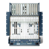
Cisco ONS 15454 SDH Procedure Manual (860 pages)
Brand:
Cisco
| Category:
Network Hardware
| Size: 16.74 MB
Table of Contents
Table of Contents
3
Cisco ONS 15454 SDH Procedure Guide
26
About this Guide
53
Appendix A CTC Information and Shortcut
54
Document Conventions
58
Related Documentation
58
CHAPTER 13 Convert Network Configurations
67
Before You Begin
67
Chapter 1 Install the Shelf and FMEC
68
Table 1-1 Cable Models and Model Numbers
69
User-Supplied Equipment
69
Tools Needed
70
NTP- D2 Install the Shelf Assembly
71
NTP- D3 Open and Remove the Front Door
72
NTP- D219 Open and Remove the FMEC Cover
73
Installing Fmecs on the ONS 15454 SDH
75
NTP- D6 Install the Power and Ground
76
NTP- D7 Install the Fan-Tray Assembly
77
Installing the Fan-Tray Assembly
78
NTP- D222 Install the E1-75/120 Conversion Panel
79
Figure 1-3 Mounting the E1-75/120 Conversion Panel in a Rack
80
NTP- D223 Attach Wires to Alarm, Timing, LAN, and Craft Pin Connections
81
NTP- D224 Install the Electrical Card Cables on the Fmecs
82
NTP- D226 Install and Close the FMEC Cover
83
NTP- D13 Perform the Shelf Installation Acceptance Test
84
Table 1-2 ONS 15454 SDH Shelf Installation Task Summary
85
Figure 2-1 Installing Cards in the ONS 15454 SDH
89
Table 2-1 ONS 15454 SDH Card and Slot Compatibility for the XC-VXL-2.5G Cards
89
Table 2-2 Slot Compatibility for the XC-VXL-10G or XC-VXC-10G Card
91
CHAPTER 2 Install Cards and Fiber-Optic Cable
94
NTP- D16 Install STM-N Cards and Connectors
94
Table 2-3 Maximum Bandwidth by Shelf Slot for the MRC-12 in Different Cross-Connect Configurations
95
NTP- D17 Install the Electrical Cards
96
NTP- D18 Install Ethernet Cards and Connectors
97
NTP- D286 Install the FC_MR-4 Cards
99
NTP- D348 Install the Filler Cards
101
NTP- D19 Install Fiber-Optic Cables on Optical Cards
103
NTP- D245 Route Fiber-Optic Cables
104
NTP- D227 Remove and Replace a Card
106
Figure 2-4 ONS 15454 SDH Front Door with Hinges and Ground Wire
108
NTP- D20 Replace the Front Door
108
Before You Begin
109
NTP- D278 Set up Computer for CTC
110
Table 3-1 CTC Computer Setup for Local Craft Connection to the ONS 15454 SDH
111
Chapter 3 Connect the PC and Log into the GUI
111
NTP- D261 Set up a Computer for a Corporate LAN Connection to the ONS 15454 SDH
113
NTP- D262 Set up a Remote Access Connection to the ONS 15454 SDH
114
Figure 17-11 Login Node Group
115
NTP- D23 Log into the ONS 15454 SDH GUI
115
Before You Begin
117
Chapter 4 Turn up a Node
118
Ntp-D30 Create Users and Assign Security
120
NTP- D30 Create Users and Assign Security
120
None
122
Purpose
122
NTP- D279 Set Power Monitor Thresholds
122
NTP- D169 Set up CTC Network Access
123
NTP- A360 Enable EMS Secure Access
124
Figure 4-2 CTC Computer and ONS 15454 SDH Nodes Residing Behind Firewalls
125
Prerequisite Procedures NTP-D24 Verify Card Installation
125
NTP- D28 Set up Timing
125
Complete the "DLP-D60 Log into CTC" Task
126
NTP-D24 Verify Card Installation
126
Onsite/Remote Onsite or Remote
126
Prerequisite Procedures
126
Purpose
126
Required/As Needed
126
Required/As Needed as Needed
126
Security Level
126
Step 1
126
Tools/Equipment None
126
Card Protection Types
127
Complete the "DLP-D60 Log into CTC" Task
128
Step 2
128
NTP- D34 Set up SNMP
128
Figure 4-3 Creating an SNMP Trap Destination
129
NTP- D326 Provision OSI
130
Chapter 5 Turn up a Network
132
Before You Begin
133
NTP- D124 Provision a Point-To-Point Network
134
Figure 5-1 Linear ADM Configuration
137
NTP- D38 Provision a Linear ADM Network
138
NTP- D340 Linear ADM Network Acceptance Test
139
Figure 5-2 Four-Node, Two-Fiber MS-Spring Fiber Connection Example
141
NTP- D40 Provision MS-Spring Nodes
141
Figure 5-3 Four-Node, Four-Fiber Ms-Spring Fiber Connection Example
142
NTP- D41 Create the MS-Spring
144
NTP- D341 Two-Fiber MS-Spring Acceptance Test
145
NTP- D342 Four-Fiber MS-Spring Acceptance Test
147
NTP- D304 Provision a Traditional MS-Spring Dual-Ring Interconnect
149
Figure 5-4 Traditional Two-Fiber MS-Spring DRI Fiber Connection Example
150
NTP- D305 Provision an Integrated MS-Spring Dual-Ring Interconnect
151
Figure 5-5 Integrated Two-Fiber MS-Spring DRI Example
152
Figure 5-6 SNCP Fiber Connection Example
153
NTP- D44 Provision SNCP Nodes
153
NTP- D343 SNCP Acceptance Test
155
Figure 5-7 SNCP DRI Fiber Connection Example
157
NTP- D217 Provision a Traditional SNCP Dual-Ring Interconnect
157
Figure
158
Slot Slot 5
159
NTP- D218 Provision an Integrated SNCP Dual-Ring Interconnect
159
Step 1
160
NTP- D306 Provision a Traditional MS-Spring/Sncp Dual-Ring Interconnect
161
Step 1
162
Figure 5-10 Integrated MS-Spring to SNCP DRI Example
163
NTP- D307 Provision an Integrated MS-Spring/Sncp Dual-Ring Interconnect
163
Figure 5-11 ONS 15454 SDH Open-Ended Sncps Fiber Connection Example
165
NTP- D258 Provision an Open-Ended SNCP
165
Repeat Steps
166
Step 5
166
DLP-D81 Provision a Proxy Tunnel" Task on Page
166
DLP-D90 Provision a Firewall Tunnel" Task on Page
166
NTP- D344 Open-Ended SNCP Acceptance Test
167
Figure 5-12 SNCP Subtended from an MS-Spring
169
NTP- D46 Subtend an SNCP from an MS-Spring
169
Ntp-D47 Subtend an Ms-Spring from an Sncp
170
NTP- D47 Subtend an MS-Spring from an SNCP
170
Figure 5-13 MS-Spring Subtended from an MS-Spring
171
Figure 5-14 View Subtended MS-Springs on the Network Map
172
Step 3
172
Step 9 Repeat Step
172
Stop. You Have Completed this Procedure
172
NTP- D48 Subtend an MS-Spring from an MS-Spring
172
As Needed
173
Step 1
173
Stop. You Have Completed this Procedure
173
NTP- D172 Create a Logical Network Map
174
CHAPTER 14 Add and Remove Nodes
175
Before You Begin
175
Table 6-1 ONS 15454 SDH Circuit Options
177
Table 6-2 CTC Circuit Source and Destination Options for Low-Order VC3 Circuits
177
C H a P T E R 6 Create Circuits and Low-Order Tunnels
177
Table 6-3 CTC Circuit Source and Destination Options for Low-Order VC12 or VC11 Circuits
178
Table 6-4 CTC Circuit Source and Destination Options for High-Order VC4 Circuits
178
Provisioning or Higher
179
Step 1
179
CHAPTER 6 Create Circuits and Low-Order Tunnels
179
NTP- D127 Verify Network Turn-Up
179
Figure 6-2 Setting Circuit Routing Preferences
184
NTP- D335 Create a Manually Routed Low-Order VC11 Circuit
186
NTP- D336 Create a Unidirectional Low-Order VC11 Circuit with Multiple Drops
189
NTP- D81 Create an Automatically Routed Low-Order VC12 Circuit
193
Figure 6-3 Setting Circuit Attributes for a Low-Order VC12 Circuit
195
Figure 6-4 Setting Circuit Routing Preferences
196
NTP- D82 Create a Manually Routed Low-Order VC12 Circuit
198
NTP- D83 Create a Unidirectional Low-Order VC12 Circuit with Multiple Drops
201
NTP- D54 Create an Automatically Routed Low-Order VC3 Circuit
205
Figure 6-5 Setting Circuit Attributes for a Low-Order VC3 Circuit
206
NTP- D55 Create a Manually Routed Low-Order VC3 Circuit
209
NTP- D56 Create a Unidirectional Low-Order VC3 Circuit with Multiple Drops
212
Figure 6-6 Setting Circuit Attributes for a Unidirectional Low-Order VC3 Circuit
214
NTP- D133 Create an Automatically Routed Low-Order Tunnel
216
Figure 6-7 Setting Attributes for a Low-Order Tunnel
218
NTP- D134 Create a Manually Routed Low-Order Tunnel
219
NTP- D216 Create a Low-Order Path Tunnel for Port Grouping
221
NTP- D187 Create a Low-Order Aggregation Point
224
Figure 6-8 Setting Attributes for a Low-Order Aggregation Point
225
NTP- D135 Test Low-Order Circuits
227
NTP- D323 Create an Automatically Routed High-Order Circuit
229
Figure 6-9 Setting Circuit Attributes for an High-Order Circuit
231
NTP- D324 Create a Manually Routed High-Order Circuit
234
NTP- D190 Create a Unidirectional High-Order Circuit with Multiple Drops
237
NTP- D62 Test High-Order Circuits
240
NTP- D139 Create a Half Circuit on an MS-Spring or 1+1 Node
242
NTP- D140 Create a Half Circuit on an SNCP Ring Node
244
NTP- D191 Create an E-Series Etherswitch Circuit (Multicard or Single-Card Mode)
246
NTP- D192 Create a Circuit for an E-Series Card in Port-Mapped Mode
249
NTP- D142 Create an E-Series Shared Packet Ring Ethernet Circuit
251
NTP- D143 Create an E-Series Hub-And-Spoke Ethernet Configuration
254
NTP- D144 Create an E-Series Single-Card Etherswitch Manual Cross-Connect
256
NTP- D145 Create an E-Series Multicard Etherswitch Manual Cross-Connect
259
NTP- D146 Test E-Series Circuits
263
NTP- D148 Create a Manual Cross-Connect for a G-Series or E-Series Card in Port-Mapped Mode
264
NTP- D241 Provision G-Series Ports for Transponder Mode
266
Figure 6-10 Two Port Bidirectional Transponder Mode
267
Figure 6-11 One Port Bidirectional Transponder Mode
268
Figure 6-12 Two-Port Unidirectional Transponder Mode
269
NTP- D149 Test G-Series Circuits
269
NTP- D194 Create Overhead Circuits
270
NTP- D283 Create an Automatically Routed VCAT Circuit
271
Figure 6-13 Setting VCAT Circuit Attributes
273
Figure 6-14 Automatically Routing a VCAT Circuit
273
NTP- D284 Create a Manually Routed VCAT Circuit
275
NTP- D325 Create an STM Test Circuit Around the Ring
277
NTP- D350 Create a Server Trail
280
Chapter 7 Manage Circuit
285
NTP- D287 Modify and Delete Circuits
286
NTP- D78 Create a Monitor Circuit
287
Figure
288
NTP- D79 Create a J1 or J2 Path Trace
290
NTP- D332 Bridge and Roll Traffic
291
Figure
292
NTP- D310 Merge Circuits
293
Before You Begin
295
CHAPTER 8 Monitor Performance 8-1
296
NTP- D257 Change the PM Display
296
NTP- D198 Monitor Ethernet Performance
298
NTP- D289 Create and Delete Ethernet RMON Thresholds
299
NTP- D301 Monitor FC_MR-4 Performance
300
Before You Begin
303
Chapter 9 Manage Alarm
304
Figure
306
NTP- D70 View Alarm Counts on the LCD for a Node, Slot, or Port
307
NTP- D71 Create, Download, and Assign Alarm Severity Profiles
308
NTP- D168 Enable, Modify, or Disable Alarm Severity Filtering
309
NTP- D247 Provision External Alarms and Controls on the Alarm Interface Controller–International
310
Figure 9-3 Provisioning External Alarms on the AIC-I Card
311
Before You Begin
313
NTP- D88 Modify Line Settings and PM Parameter Thresholds for Electrical Cards
314
Chapter 10 Change Card Setting
315
NTP- D91 Upgrade E1-N-14 and DS3 I-N-12 Protect Cards from 1:1 Protection to 1:N Protection
316
NTP- D311 Modify Port Settings and PM Parameter Thresholds for SAN Cards
317
NTP- D331 Manage Pluggable Port Modules
318
Before You Begin
321
Chapter 11 Change Node Setting
322
NTP- D327 Modify OSI Provisioning
323
NTP- D202 Customize the CTC Network View
324
NTP- D203 Modify or Delete Card Protection Settings
325
NTP- D85 Change Node Timing
326
NTP- D205 Modify Users and Change Security
327
Before You Begin
329
NTP- D234 Upgrade the XC-VXL-2.5G Card to the XC-VXL-10G or XC-VXC-10G Card
330
Chapter 12 Upgrade Card and Span
331
NTP- D333 Upgrade the XC-VXL-10G Card to the XC-VXC-10G Card
332
NTP- D314 Upgrade the TCC2 Card to the TCC2P Card
333
NTP- D94 Upgrade STM-N Cards and Spans Automatically
335
Figure 12-1 Span Upgrade Shortcut Menu
337
Figure 12-2 Span Upgrade Wizard
338
NTP- D95 Upgrade Optical Spans Manually
338
NTP- D374 Upgrade STM-N Cards Manually
340
Port Migration Information
341
C H a P T E R 13 Convert Network Configurations
344
Figure
345
NTP- D154 Convert a Point-To-Point to a Linear ADM Manually
347
Automatically
349
Figure
351
NTP- D351 Convert a Point-To-Point or Linear ADM to an SNCP Automatically
352
NTP- D156 Convert a Point-To-Point or Linear ADM to an SNCP Manually
353
NTP- D320 Convert an SNCP to a Two-Fiber MS-Spring Automatically
355
NTP- D210 Convert an SNCP to a Two-Fiber MS-Spring Manually
357
NTP- D211 Convert a Two-Fiber MS-Spring to a Four-Fiber MS-Spring Automatically
359
NTP- D159 Modify an MS-Spring
361
Before You Begin
363
Figure
364
Figure 14-1 Three-Node, Two-Fiber MS-Spring before a Fourth Node Is Added
365
NTP- D353 Add an MS-Spring Node
365
Figure 14-2 Three-Node, Four-Fiber MS-Spring before a Fourth Node Is Added
366
Figure
368
NTP- D213 Remove an MS-Spring Node
370
NTP- D105 Add an SNCP Node
373
NTP- D106 Remove an SNCP Node
375
NTP- D280 Add a Node to a Linear ADM Manually
376
NTP- D337 Add a Node to a Linear ADM Using the Wizard
378
Figure 14-4 Selecting Protection Group Ports
379
Figure 14-5 Refibering the Protect Path
379
NTP- D322 Remove an In-Service Node from a Linear ADM
381
Before You Begin
383
NTP- D107 Inspect and Maintain the Air Filter
384
Figure 15-1 Reusable Fan-Tray Air Filter in an External Filter Bracket (Front Door Removed)
385
Chapter 15 Maintain the Node
385
NTP- D108 Back up the Database
387
NTP- D109 Restore the Database
388
Figure 15-2 Restoring the TCC2/TCC2P Database
389
NTP- D328 View and Manage OSI Information
390
NTP- D163 Restore the Node to Factory Configuration
391
NTP- D312 Viewing the Audit Trail Records
392
Figure 15-4 Viewing the Audit Trail Records
393
Table 15-1 Audit Trail Column Definitions
393
NTP- D214 Off-Load the Audit Trail Record
394
NTP- D313 Off-Load the Diagnostics File
395
NTP- D231 Initiate or Clear an External Switching Command
396
NTP- D112 Clean Fiber Connectors
397
NTP- D153 Reset a Card Using CTC
398
NTP- D266 View E-Series Ethernet Maintenance Information
399
NTP- D233 Change the Node Timing Reference
400
Table 15-2 ONS 15454 SDH Timing Report
401
NTP- D229 Replace an In-Service Cross-Connect Card
403
NTP- D230 Replace the Fan-Tray Assembly
404
Table 15-3 Incompatibility Alarms
405
Figure 15-5 Removing or Replacing the Fan-Tray Assembly (Front Door Removed)
406
NTP- D345 Edit Network Element Defaults
407
NTP- D346 Import Network Element Defaults
408
NTP- D347 Export Network Element Defaults
409
Chapter 16 Power down the Node
412
CHAPTER 17 Dlps D1 to D99 17-1
415
DLP- D1 Unpack and Verify the Shelf Assembly
415
DLP- D2 Inspect the Shelf Assembly
416
DLP- D4 Create an IP-Encapsulated Tunnel
417
DLP- D5 Mount the Shelf Assembly in a Rack (One Person)
418
Figure 17-1 Mounting an ONS 15454 SDH in a Rack
419
DLP- D6 Mount the Shelf Assembly in a Rack (Two People)
420
DLP- D7 Mount Multiple Shelf Assemblies in a Rack
421
DLP- D8 Open the Front Cabinet Compartment (Door)
423
DLP- D9 Remove the Front Door
424
DLP- D14 Create a Four-Fiber MS-Spring Using the MS-Spring Wizard
425
Table
427
Figure 17-5 Grounding the ONS 15454 SDH
428
DLP- D17 Connect Office Power to the ONS 15454 SDH Shelf
429
DLP- D18 Turn on and Verify Office Power
430
DLP- D22 Install Fiber-Optic Cables in a 1+1 Configuration
431
Figure 17-6 Installing Fiber-Optic Cables
432
DLP- D23 View Spanning Tree Information
433
DLP- D25 Configure the CTC Alerts Dialog Box for Automatic Popup
434
DLP- D27 Delete Circuits
435
DLP- D28 Create a Four-Fiber MS-Spring Manually
436
DLP- D29 Change Tunnel Type
438
DLP- D30 Repair an IP Tunnel
439
DLP- D32 Inspect the Shelf Installation and Connections
440
DLP- D34 Delete Vlans
441
DLP- D36 Provision a VCAT Circuit Source and Destination
442
DLP- D37 Reset a TCC2/TCC2P Card Using CTC
443
DLP- D38 Reset a Traffic Card in CTC
444
DLP- D40 Create a Provisionable Patchcord
445
DLP- D41 Delete a Provisionable Patchcord
447
DLP- D43 Initiate an Optical Protection Switch
448
DLP- D44 Initiate an Electrical Protection Switch
449
Using Static IP Addresses
451
DLP- D51 Set up a Windows PC for Craft Connection to an ONS 15454 SDH Using Dynamic Host Configuration Protocol
453
DLP- D52 Set up a Windows PC for Craft Connection to an ONS 15454 SDH Using Automatic Host Detection
456
DLP- D53 Set up a Solaris Workstation for a Craft Connection to an ONS 15454 SDH
459
DLP- D54 Delete a Node from a Specified Login Node Group
461
DLP- D57 Disable Proxy Service Using Netscape (Windows and UNIX)
462
DLP- D60 Log into CTC
463
Logging into CTC
464
DLP- D61 Create Login Node Groups
465
DLP- D62 Add a Node to the Current Session or Login Group
467
Selecting the IP Address Option
468
Selecting the Save Configuration Option
469
DLP- D65 Create a Static Route
470
DLP- D67 Provision the IIOP Listener Port on the ONS 15454 SDH
471
DLP- D69 Set up External or Line Timing
472
DLP- D70 Set up Internal Timing
475
DLP- D71 Create a 1:1 Protection Group
476
DLP- D72 Create a 1:N Protection Group
477
DLP- D73 Create a 1+1 Protection Group
478
DLP- D74 Create a New User on a Single Node
479
DLP- D75 Create a New User on Multiple Nodes
480
DLP- D76 Add a Member to a VCAT Circuit
481
DLP- D77 Delete a Member from a VCAT Circuit
483
DLP- D78 Install the TL1 Craft Interface on the MIC-C/T/P
484
DLP- D79 Remove Pass-Through Connections
485
DLP- D80 Change a VCAT Member Service State
486
DLP- D81 Provision a Proxy Tunnel
487
DLP- D82 View Alarms
488
Alarm Column Descriptions
489
DLP- D83 Provision Orderwire
490
DLP- D84 Enable Node Security Mode
491
DLP- D85 Lock Node Security
493
DLP- D87 Disable Node Security Mode
494
DLP- D88 Optical 1+1 Protection Test
495
DLP- D89 Remap the K3 Byte
497
DLP- D91 MS-Spring Switch Test
498
DLP- D92 Four-Fiber MS-Spring Exercise Span Test
502
DLP- D93 Four-Fiber MS-Spring Span Switching Test
503
DLP- D94 SNCP Protection Switching Test
505
DLP- D95 Provision a Low-Order VC12 Circuit Source and Destination
507
DLP- D96 Provision a Low-Order VC3 Circuit Route
508
DLP- D97 Provision a High-Order Circuit Source and Destination
509
DLP- D98 Provision a High-Order Circuit Route
510
Manually Routing an STM-N Circuit
511
DLP- D99 Determine Available Vlans
512
CHAPTER 18 Dlps D100 to D199 18-1
513
DLP- D100 Delete a Proxy Tunnel
513
DLP- D102 Hard-Reset a CE-100T-8 Card Using CTC
514
DLP- D103 Soft-Reset a CE100T-8 Card Using CTC
515
Figure
516
DLP- D105 Configure the Node for RADIUS Authentication
517
Figure 18-2 RADIUS Server Tab
518
Figure 18-3 Create RADIUS Server Entry Window
518
DLP- D106 View and Terminate Active Logins
519
Table 18-1 STM-N Card Line Settings
521
DLP- D109 Change Optics Thresholds Settings for STM-64 and MRC-12 Cards
524
DLP- D111 Changing the Maximum Number of Session Entries for Alarm History
526
DLP- D112 Display Alarms and Conditions Using Time Zone
527
DLP- D114 View Conditions
528
DLP- D117 Apply Alarm Profiles to Cards and Nodes
530
DLP- D121 Enable Pointer Justification Count Performance Monitoring
531
Figure 18-7 Enabling or Disabling Pointer Justification Count Parameters
532
Table 18-3 Traffic Cards that Terminate the Line (Ltes)
532
DLP- D122 Enable Intermediate Path Performance Monitoring
533
VC4 Tab for Enabling or Disabling IPPM
534
DLP- D124 Refresh PM Counts at 15-Minute Intervals
535
DLP- D126 View Near-End PM Counts
536
DLP- D127 View Far-End PM Counts
537
DLP- D131 Search for Circuits
538
DLP- D132 Provision a Multirate PPM on the MRC-12 Card
539
DLP- D134 Change the Optical Line Rate on the MRC-12 Card
540
DLP- D135 Delete a PPM from the MRC-12 or STM64-XFP Card
541
DLP- D136 Provision CE-100T-8 Ethernet Ports
542
DLP- D137 Provision a J1 Path Trace on STM-N Ports
543
DLP- D140 Change the Node Name, Date, Time, and Contact Information
544
DLP- D141 Provision CE-100T-8 and CE-1000-4 POS Ports
545
DLP- D142 Modify a Static Route
546
DLP- D143 Delete a Static Route
547
DLP- D144 Disable OSPF
548
DLP- D146 Print CTC Data
549
DLP- D147 Export CTC Data
550
Figure 18-10 Selecting CTC Data for Export
551
DLP- D148 Create Domain Icons
552
DLP- D149 Manage Domain Icons
553
DLP- D150 Modify a 1:1 Protection Group
554
DLP-D151 Set up SNMP for a GNE
555
Table 18-5 Managing Domains
554
DLP- D152 Modify a 1:N Protection Group
556
DLP- D153 Set up SNMP for an ENE
557
DLP- D154 Modify a 1+1 Protection Group
558
DLP- D155 Delete a Protection Group
559
DLP- D157 Change the Node Timing Source
560
DLP- D158 Change User Password and Security Level on a Single Node
561
DLP- D159 Delete a User on a Single Node
562
DLP- D161 Delete a User on Multiple Nodes
563
DLP- D162 Format and Enter NMS Community String for SNMP Command or Operation
564
DLP- D163 Delete SNMP Trap Destination
565
DLP- D166 Provision or Modify TARP Operating Parameters
567
DLP- D167 Add a Static TID to NSAP Entry to the TARP Data Cache
569
DLP- D169 Add a TARP Manual Adjacency Table Entry
570
DLP- D171 Provision OSI Routers
571
DLP- D172 Provision Additional Manual Area Addresses
572
DLP- D174 Create an IP-Over-CLNS Tunnel
574
DLP- D175 Remove a TARP Manual Adjacency Table Entry
575
DLP- D177 Convert Ds3I-N-12 Cards from 1:1 to 1:N Protection
577
DLP- D178 Change the OSI Routing Mode
578
DLP- D179 Edit the OSI Router Configuration
579
DLP- D180 Edit the OSI Subnetwork Point of Attachment
580
DLP- D181 Edit an IP-Over-CLNS Tunnel
581
DLP- D182 Delete an IP-Over-CLNS Tunnel
582
DLP- D184 View ES-IS Routing Information Base
583
DLP- D185 Manage the TARP Data Cache
584
DLP- D186 Provision a Low-Order VC11 Circuit Source and Destination
585
DLP- D187 Provision a Low-Order VC11 Circuit Route
586
DLP- D188 View CE-Series Ethernet and POS Ports Statistics PM Parameters
587
Ether Ports Statistics on the Card View Performance Window
588
DLP- D189 Verify that a 1+1 Working Slot Is Active
589
DLP- D190 View CE-Series Ethernet and POS Ports Utilization PM Parameters
590
DLP- D191 Delete a Card
591
DLP- D192 View CE-Series Ethernet and POS Ports History PM Parameters
592
DLP- D193 Grant Superuser Privileges to a Provisioning User
593
DLP- D194 Clear an MS-Spring Force Ring Switch
594
DLP- D196 Delete an MS-Spring from a Single Node
595
DLP- D197 Initiate an SNCP Force Switch
596
DLP- D198 Clear an SNCP Force Switch
597
CHAPTER 19 Dlps D200 to D299 19-1
599
DLP- D201 Apply a Lock-On
599
DLP- D202 Apply a Lockout
600
DLP- D203 Clear a Lock-On or Lockout
601
DLP- D205 Clean Fiber Connectors with CLETOP
602
DLP- D207 Delete a Server Trail
603
DLP- D209 Change External Controls Using the AIC-I Card
604
DLP- D210 Change AIC-I Card Orderwire Settings
605
Table
606
DLP- D212 Create a User Data Channel Circuit
607
DLP- D214 Change the Service State for a Port
608
DLP- D215 Consolidate Links in Network View
609
Figure 19-1 Unconsolidated Links in Network View
610
Figure 19-2 Consolidated Links in Network View
610
Figure 19-3 Network View with Local Link Consolidation
611
Table 19-1 Link Classes by Network Scope
611
Figure 19-4 Protection Operation on a Three-Node MS-Spring
614
DLP- D218 Provision SNCP Ring Selectors During Circuit Creation
615
DLP- D219 Provision a Low-Order Tunnel Route
616
DLP- D221 Provision E-Series Ethernet Ports for VLAN Membership
617
Table
618
DLP- D222 Provision G-Series Ethernet Ports
619
DLP- D223 Download an Alarm Severity Profile
620
DLP- D224 Adjust the Java Virtual Memory Heap Size
621
DLP- D225 Enable Alarm Filtering
622
DLP- D227 Disable Alarm Filtering
623
DLP- D230 Change a Circuit State
624
DLP- D231 Edit a Circuit Name
625
DLP- D232 Change Active and Standby Span Color
626
DLP- D233 Edit SNCP Circuit Path Selectors
627
DLP- D234 Roll the Source or Destination of One Optical Circuit
628
Selecting Single Roll Attributes
629
Figure 19-7 Selecting a New Endpoint
630
DLP- D235 Roll One Cross-Connect from an Optical Circuit to a Second Optical Circuit
631
Figure 19-9 Selecting Roll Attributes for a Single Roll Onto a Second Circuit
632
DLP- D236 Roll Two Cross-Connects on One Optical Circuit Using Automatic Routing
633
Figure 19-10 Selecting Dual Roll Attributes
634
Figure 19-11 Setting Roll Routing Preferences
635
DLP- D237 Roll Two Cross-Connects on One Optical Circuit Using Manual Routing
637
DLP- D238 Roll Two Cross-Connects from One Optical Circuit to a Second Optical Circuit
639
DLP- D239 Delete a Roll
641
DLP- D241 Clear an MS-Spring Manual Ring Switch
642
DLP- D242 Create an MS-Spring on a Single Node
643
DLP- D243 Create a VLAN
644
Figure 19-12 Reinitialization Tool
645
DLP- D245 Use the Reinitialization Tool to Clear the Database and Upload Software (UNIX)
647
DLP- D246 Provision E-Series Ethernet Card Mode
648
DLP- D247 Change an STM-N Card
649
DLP- D248 Delete Vlans
650
Table
652
Table
653
DLP- D250 Set up or Change Open Shortest Path First Protocol
654
Table
655
DLP- D251 Set up or Change Routing Information Protocol
656
DLP- D254 TCC2/TCC2P Card Active/Standby Switch Test
657
DLP- D255 Cross-Connect Card Side Switch Test
658
DLP- D256 View Ethernet Statistics PM Parameters
659
DLP- D257 View Ethernet Utilization PM Parameters
660
DLP- D258 View Ethernet History PM Parameters
661
DLP- D260 Set Auto-Refresh Interval for Displayed PM Counts
662
DLP- D261 Refresh PM Counts for a Different Port
663
DLP- D263 Edit SNCP Dual-Ring Interconnect Circuit Hold-Off Timer
665
DLP- D264 Provision a J1 Path Trace on Circuit Source and Destination Ports
666
DLP- D265 Change the Login Legal Disclaimer
669
DLP- D266 Change IP Settings
670
DLP- D268 Apply a Custom Network View Background Map
671
DLP- D269 Enable Dialog Box Do-Not-Display Option
672
DLP- D272 Change Node Security Policy on Multiple Nodes
674
DLP- D273 Modify SNMP Trap Destination
675
DLP- D293 Perform a Manual Span Upgrade on a Two-Fiber MS-Spring
676
DLP- D294 Perform a Manual Span Upgrade on a Four-Fiber MS-Spring
677
DLP- D295 Perform a Manual Span Upgrade on an SNCP
678
DLP- D296 Perform a Manual Span Upgrade on a 1+1 Protection Group
679
DLP- D297 Perform a Manual Span Upgrade on an Unprotected Span
680
DLP- D298 Check the Network for Alarms and Conditions
681
DLP- D299 Initiate an MS-Spring Span Lockout
682
CHAPTER 20 Dlps D300 to D399 20-1
685
DLP- D300 Clear an MS-Spring Span Lockout
685
DLP- D301 Initiate an MS-Spring Manual Ring Switch
686
DLP- D309 View Ethernet MAC Address Table
688
DLP- D310 View Ethernet Trunk Utilization
689
DLP- D312 Provision a Half Circuit Source and Destination on an SNCP Ring
690
DLP- D314 Assign a Name to a Port
691
DLP- D316 Log out a User on Multiple Nodes
692
Table 20-1 Alarm Pin Assignments
697
DLP- D325 Install Timing Cables on the MIC-C/T/P
699
DLP- D326 Install LAN Wires on the MIC-C/T/P
700
DLP- D328 Install 75-Ohm E-1, E-3, or STM-1 Coaxial Cables
701
DLP- D329 Install 120-Ohm E-1 Cables with DB-37 Connectors to the Fmecs
702
DLP- D330 Install 120-Ohm E-1 Cables with Molex 96-Pin LFH Connectors
704
Table 20-6 Pinout for E-1 Interfaces on Ports 1 to
705
Table 20-7 Pinout for E-1 Interfaces on Ports 22 to
705
DLP- D332 Install the TCC2/TCC2P Cards
706
DLP- D333 Install the XC-VXL-10G, XC-VXL-2.5G, or XC-VXC-10G Cards
709
DLP- D334 Install the Alarm Interface Controller–International Card
710
DLP- D335 Install GBIC or SFP/XFP Devices
712
Figure 20-5 GBIC Installation (with Clips)
715
DLP- D336 Remove GBIC or SFP/XFP Device
716
Figure 20-6 Connecting Fiber to a Four-Node SNCP
718
Figure 20-7 Connecting Fiber to an Eight-Node SNCP DRI
719
Figure 20-8 Connecting Fiber to a Six-Node Integrated SNCP DRI
720
DLP- D338 Install Fiber-Optic Cables for MS-Spring Configurations
721
Figure 20-9 Connecting Fiber to a Four-Node, Two-Fiber MS-Spring
722
DLP- D365 Change Line and Threshold Settings for E1-N-14 or E1-42 Cards
723
Table 20-10 Line Options for E1-N-14 and E1-42 Cards
724
Table 20-11 Line Thresholds Options for E1-N-14 and E1-42 Cards
725
Table 20-12 Electrical Path Threshold Options for E1-N-14 and E1-42 Cards
726
Table 20-13 SDH Threshold Options for E1-N-14 and E1-42 Cards
726
DLP- D340 Change Line and Threshold Settings for the E3-12 Cards
727
Table 20-14 Line Options for E3-12 Cards
728
Table 20-15 Line Threshold Options for E3-12 Cards
729
Table 20-16 Electrical Path Threshold Options for E3-12 Cards
730
Table 20-17 SDH Threshold Options for E3-12 Cards
730
DLP- D341 Change Line and Threshold Settings for the Ds3I-N-12 Cards
731
Table 20-18 Line Options for the Ds3I-N-12 Cards
732
Table 20-19 Line Threshold Options for the Ds3I-N-12 Cards
733
Table 20-20 Electrical Path Options for the Ds3I-N-12 Cards
734
Table 20-21 SDH Threshold Options for Ds3I-N-12 Cards
734
DLP- D342 Change Line and Threshold Settings for the STM1E-12 Card
735
Table 20-22 Line Options for the STM1E-12 Card
736
Table 20-23 Port Options for the STM1E-12 Card
736
Threshold Options for the STM1E-12 Card
737
DLP- D343 Change SDH Threshold Settings for STM-N Cards
738
Table 20-26 STM-N Threshold Options
739
DLP- D348 View ML-Series Ether Ports PM Parameters
740
DLP- D349 View ML-Series POS Ports PM Parameters
741
DLP- D353 Provision G-Series Flow Control Watermarks
742
DLP- D354 Change General Port Settings for the FC_MR-4 Card
743
Table 20-27 FC_MR-4 Card General Port Settings
744
DLP- D355 Change Distance Extension Port Settings for the FC_MR-4 Card
745
Table 20-28 FC_MR-4 Card Distance Extension Port Settings
746
DLP- D356 Change Enhanced FC/FICON Port Settings for the FC_MR-4 Card
747
DLP- D357 Verify Pass-Through Circuits
748
DLP- D358 Change a Multiplex-Section DCC Termination
749
DLP- D360 Delete a Regenerator-Section DCC Termination
750
DLP- D362 Delete a Multiplex-Section DCC Termination
752
DLP- D364 Provision Multiplex-Section DCC Terminations
755
DLP- D367 Provision a J2 Path Trace on Circuit Source and Destination Ports
756
Table 20-30 ONS 15454 SDH Cards Capable of J2 Path Trace
757
DLP- D368 Manual or Force Switch the Node Timing Reference
759
DLP- D369 Clear a Manual or Force Switched Node Timing Reference
760
Table 20-31 Circuit Protection Types
761
Cisco ONS 15454 SDH Circuit Status
762
DLP- D371 View the MS-Spring Squelch Table
764
DLP- D372 Import a Cisco Metroplanner Configuration File
765
DLP- D393 Switch between TDM and DWDM Network Views
766
CHAPTER 21 Dlps D400 to D499 21-1
767
DLP- D420 Install the Public-Key Security Certificate
767
DLP- D422 Change the JRE Version
770
DLP- D425 Create a New or Cloned Alarm Severity Profile
772
Figure 21-2 Network View Alarm Profiles Window
773
Figure 21-3 Store Profile(S) Dialog Box
774
DLP- D426 Apply Alarm Profiles to Ports
775
Figure 21-4 Port Alarm Profile for an OC3 IR/STM1 SH 1310-8 Card
776
DLP- D427 Delete Alarm Severity Profiles
777
DLP- D428 Modify Alarm, Condition, and History Filtering Parameters
778
Alarm Filter Dialog Box General Tab
779
Figure 21-7 Alarm Filter Dialog Box Conditions Tab
780
DLP- D430 Suppress Alarm Reporting
781
DLP- D431 Discontinue Alarm Suppression
782
DLP- D432 View Port Status on the LCD
783
DLP- D433 Run the CTC Installation Wizard for Windows
784
DLP- D434 Run the CTC Installation Wizard for UNIX
787
DLP- D435 Change the Default Network View Background Map
790
DLP- D436 Delete Ethernet RMON Alarm Thresholds
791
DLP- D438 Change Port Settings for the FC_MR-4 Card
792
DLP- D441 Create Ethernet RMON Alarm Thresholds
794
DLP- D442 Preprovision a Slot
799
DLP- D458 Monitor PM Counts for a Selected Signal
800
Figure 21-10 Line Drop-Down List for an STM-16 Card
801
DLP- D459 Clear Selected PM Counts
802
DLP- D460 View FC_MR-4 Statistics PM Parameters
803
DLP- D461 View FC_MR-4 Utilization PM Parameters
804
DLP- D462 View FC_MR-4 History PM Parameters
805
DLP- D463 Refresh FC_MR-4 PM Counts at a Different Time Interval
806
Table
807
Table
808
DLP- D466 Delete FC_MR-4 RMON Alarm Thresholds
810
DLP- D469 Create a Two-Fiber MS-Spring Manually
812
DLP- D470 Manually Route an SNCP Circuit for a Topology Upgrade
813
DLP- D471 Automatically Route an SNCP Circuit for a Topology Upgrade
814
DLP- D493 Provision the Ethernet Port of the ML-Series Card
815
DLP- D494 Provision the POS Port of the ML-Series Card
816
Display Node, Card, and Network Views
819
Table A-1 Change CTC Views
820
Node Icons on the Network View Map
820
Table A-2 Description of Node Icons on Network View Map
821
Manage the CTC Window
822
Table A-3 CTC Menu and Toolbar Options
823
CTC Mouse Options
826
Table A-4 CTC Window Mouse Shortcuts
827
Table A-5 Performing Node View Card Shortcuts
828
Table Display Options
829
Equipment Inventory
830
Advertisement
Cisco ONS 15454 SDH Manual (146 pages)
Brand:
Cisco
| Category:
Server
| Size: 1.77 MB
Cisco ONS 15454 SDH Procedure Manual (22 pages)
Install Cards and Fiber-Optic Cable
Brand:
Cisco
| Category:
Network Hardware
| Size: 0.82 MB
Table of Contents
Before You Begin
1
Table of Contents
10
Step 4
11
Step 8 Continue with the Stop. You Have Completed this Procedure.
11
Purpose
11
Tools/Equipment
11
Prerequisite Procedures
11
Required/As Needed
11
Onsite/Remote
11
Security Level
11
Warning
11
Touch the Backplane with Your Hand or any Metal Tool, or You Could Shock Yourself. Statement
11
Step 1 if You Installed XC-VXL-2.5G Cards, Review
12
Card/Slot Compatibility
12
Step 1
12
Note
12
NTP-D15 Install the Common Control Cards
12
As Needed Onsite None
12
If You Install the Wrong Card in a Slot, Complete the Procedure on Page
13
DLP-D335 Install GBIC or SFP/XFP Devices" Task on
17
Table
17
Table
18
Advertisement
Advertisement
Related Products
Cisco ONS 15454 SDH E1-75
cisco ONS 15454
Cisco ONS 15454 M2
Cisco ONS 15454 M6
Cisco ONS 15454 M12
Cisco ONS 15600 Series
Cisco ONS 15200 Series
Cisco ONS 15252
Cisco ONS 15201
Cisco ONS 15540 ESP
Cisco Categories
Switch
IP Phone
Network Router
Wireless Access Point
Conference System
More Cisco Manuals
Login
Sign In
OR
Sign in with Facebook
Sign in with Google
Upload manual
Upload from disk
Upload from URL