
Related Manuals for Honeywell 4909 CPVC


Summary of Contents for Honeywell 4909 CPVC
- Page 1 4909 CPVC Conductivity Cell Insertion/Removal Assembly Operations Manual 70-82-25-19 Rev. 1 7/99...
- Page 2 In no event is Honeywell liable to anyone for any indirect, special or consequential damages. The information and specifications in this document are subject to change without notice.
-
Page 3: About This Document
Abstract The purpose of this document is to support the installation operation and maintenance of the 4909 CPVC Conductivity Cell Removal/Insertion Assembly. Revision Notes The following list provides notes concerning all revisions of this document. Rev. ID Date 11/96 6/99... - Page 4 Organization Telephone Address Honeywell TAC 1-800-243-9883 Voice 1100 Virginia Drive Fort Washington, PA 19034 4909 CPVC Conductivity Cell Insertion/Removal Assembly– Operations Manual 7/99...
-
Page 5: Table Of Contents
Model Selection Guide ...8 ...8 INSTALLATION ...11 Requirements ...11 Location and Position ...11 Considerations ...11 Prepare Assembly ...12 Initial Prep ...12 Mounting into the Process ...12 Insertion ...13 Removal ...14 Electrical Connections ...14 7/99 4909 CPVC Conductivity Cell Insertion/Removal Assembly– Operations Manual Contents... - Page 6 MAINTENANCE AND REPLACEMENT PARTS ...17 To Clean The Cell...17 Replacing Removal Device Parts...17 Ball Valve ...17 Nipples...17 Bushing And Washer...17 Replacement Parts...18 PLATINIZATION AND PLATINUM BLACK ...19 4909 CPVC Conductivity Cell Insertion/Removal Assembly– Operations Manual 7/99...
- Page 7 Table 4-2 Voltage and Time Limits for Platinizing Cells ____________________________________ 18 Figure 1-1 Temperature/Pressure* Range__________________________________________________ 2 Figure 1-2 4909 CPVC Conductivity Cell Insertion/Removal Assembly with Conductivity Cell Installed3 Figure 1-3 4909 CPVC Conductivity Cell Insertion/Removal Assembly with Universal Head_________ 3...
-
Page 9: Introduction
Electrodes are three discs on the 1 constant cell, parallel plates on the 0.1 constant cell, and a pair of concentric wires wound on the cell body on the 0.01 constant cell. 7/99 4909 CPVC Conductivity Cell Insertion/Removal Assembly– Operations Manual 1. Introduction are intended for making measurements in highly... -
Page 10: 31074357 Removal Device
4909 CPVC Conductivity Cell Insertion/Removal Assembly Operations Manual 1.3 31074357 Removal Device This device consists of a ball valve which is connected to the closed system by a 1-1/2 inch CPVC schedule 80 mounting nipple and to a housing by a 6 inch long schedule 80 CPVC nipple into which the support tube for the cell mounting is inserted. -
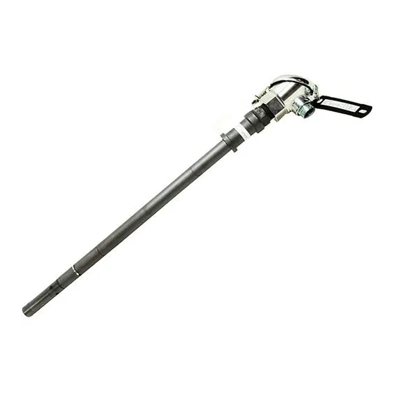
Page 11: Figure 1-3 4909 Cpvc Conductivity Cell Insertion/Removal Assembly With Universal Head
Conductivity Cell 1-1/2" NPT Nipple Adapter (Contains Automatic Temperature Compensator when Specified) Figure 1-2 4909 CPVC Conductivity Cell Insertion/Removal Assembly Figure 1-3 4909 CPVC Conductivity Cell Insertion/Removal Assembly with Universal Head 7/99 4909 CPVC Conductivity Cell Insertion/Removal Assembly– Operations Manual Valve Purge Port 6"... -
Page 12: Figure 1-4 4908 Conductivity Cell
4909 CPVC Conductivity Cell Insertion/Removal Assembly Operations Manual Adapter * * Automatic Temperature Compensator, when specified by catalog number, is mounted inside adapter. Apply teflon tape to both ends of support tube. Tighten all pipe thread fittings two turns beyond hand tight. -
Page 13: Figure 1-6 Universal Head
Set Screw Base Nipple (3/4" NPT) #6-32 Screw 7/99 4909 CPVC Conductivity Cell Insertion/Removal Assembly– Operations Manual Binding Head Gasket #6-32 Screw Chain Wire Figure 1-6 Universal Head Introduction #6-32 Terminal Screw & Board Washer Assembly View of Base with Cap Removed... - Page 14 4909 CPVC Conductivity Cell Insertion/Removal Assembly Operations Manual 4909 CPVC Conductivity Cell Insertion/Removal Assembly– Operations Manual 7/99...
-
Page 15: Specifications And Model Selection Guide
Three leads with integral automatic temp. compensator. Two leads without integral automatic temp. compensator. Four leads with integral automatic temp. compensator)Table III = 333). 7/99 4909 CPVC Conductivity Cell Insertion/Removal Assembly– Operations Manual Specifications and Model Selection Guide Polyethersulfone (PES). -
Page 16: Integral Automatic Temperature Compensation
4909 CPVC Conductivity Cell Insertion/Removal Assembly Operations Manual Integral Automatic Temperature Compensation Refer to Section 2.2 – Model Selection Guide Leadwire Tefzel covered, 18-gage cable (7 feet, 20 feet, or Universal Head, as specified). Weight Approximately 3.5 lb (1.6 Kg) (including cell). - Page 17 Table V Option = 02 Extended Length CPVC Support tube. Only available for Table V Option = 03 7/99 4909 CPVC Conductivity Cell Insertion/Removal Assembly– Operations Manual Specifications and Model Selection Guide ’7 ft. Leadwire 20 ft. Leadwire Junction Head (Aluminum)
- Page 18 4909 CPVC Conductivity Cell Insertion/Removal Assembly Operations Manual TABLE VII - OPTIONS Tagging Certificate of Calibration Notes: 1. Replacement cells only, caution look at Restrictions for insertion depth dimensions based on valve assembly type. 2. When converting from 4806 to 4909, order 4908 directly.
-
Page 19: Installation
Allow for insertion depth from the outside wall of the mounting surface as indicated by the dimensions in Fig. 3-1 or 3-2. 7/99 4909 CPVC Conductivity Cell Insertion/Removal Assembly– Operations Manual 3. Installation Installation... -
Page 20: Prepare Assembly
4909 CPVC Conductivity Cell Insertion/Removal Assembly Operations Manual Allow at least 1/2 inch clearance beyond the end of the cell and 1/8 to 3/16 inch radius clearance surrounding the cell to permit circulation of the solution. Avoid locations where excessive temperature changes may occur. -
Page 21: Insertion
If X1 is selected in Table IV of the Model Selection Guide, then the 4908 Conductivity Cell has been pre- mounted by Honeywell onto the support tube. Also cable wiring to the universal head terminal board has been completed. The valve assembly can then be mounted to the process by following steps under “Mounting into the Process”... -
Page 22: Removal
4909 CPVC Conductivity Cell Insertion/Removal Assembly Operations Manual 3.5 Removal REDUCE PROCESS PRESSURE TO 50 PSIG OR LESS. Shut off purge line, if used. Disconnect wiring connections if X1 is selected for Table IV in the MSG. DO NOT STAND BEHIND THE TUBE WHEN PERFORMING THIS STEP. While holding the compression handle from turning, turn the support grip two turns counterclockwise. -
Page 23: Figure 3-1 Outline And Dimension Drawing For 4909-X-X-X-X-03-X-X Conductivity Cell, Insertion Type With Cpvc Removal Device
Comp. WHITE Cell BLACK Linear Micromho, Resistivity, or Concentration Ranges Figure 3-1 Outline and dimension drawing for 4909-X-X-X-X-03-X-X Conductivity Cell, 7/99 4909 CPVC Conductivity Cell Insertion/Removal Assembly– Operations Manual Approx 19.7" max. (502mm) Approx 12.5" (317mm) 2.5" (64mm) Shunt Comp. -
Page 24: Figure 3-2 Outline And Dimension Drawing For 4909-X-X-X-X1-03-X-X Conductivity Cell, Insertion Type With Cpvc Removal Device And Universal Head
4909 CPVC Conductivity Cell Insertion/Removal Assembly Operations Manual X " See Below * Standard Insertion Depth Suffix A X" Approx. Approx 4.1" (105mm) * Add 6" (152 mm) to Dimensions if 074344 Support Tube is Used. 0.940" 1-1/2" NPT (24mm) Schedule 80 Nipple Temp. -
Page 25: Maintenance And Replacement Parts
Note that the support grip must be removed from the support tube before replacing the bushing and/or washer. Orient the bushing so that the tapered surface faces away from the compression handle, Fig. 1-5. 7/99 4909 CPVC Conductivity Cell Insertion/Removal Assembly– Operations Manual Maintenance and Replacement Parts... -
Page 26: Replacement Parts
4909 CPVC Conductivity Cell Insertion/Removal Assembly Operations Manual 4.3 Replacement Parts Complete Assembly Cell Assembly Complete CPVC Removal Device Universal Head Parts Platinizing Solution (3 oz. bottle) Cell Guard Tube (0.01, 0.1, and 1.0 Constants Only) Support Tube, 1/2” NPT Sch. 80, CPVC (12” Immersion) Support Tube, 1/2”... -
Page 27: Platinization And Platinum Black
Then disconnect the battery and remove the cell. Rinse the cell thoroughly in tap water and then rinse in distilled water. Pour the platinizing solution back into its container as it may be used a number of times. 7/99 4909 CPVC Conductivity Cell Insertion/Removal Assembly– Operations Manual Platinization and Platinum Black... -
Page 28: Figure 5-1 Installation Diagram-Cat. 4909 Cells With Junction Box Head Connected To 7082
4909 CPVC Conductivity Cell Insertion/Removal Assembly Operations Manual Temp. Comp. GREEN WHITE Cell BLACK Internal Cell Assembly Configuration View of Junction Box Head 4905 4973 4974 4908 4909 NOTES: 1. For pure water samples in non-conductive (plastic, glass, etc.) piping, ground the black cell electrode lead near the cell. Alternatively, connect to the 7082 ground screw as shown dotted. -
Page 29: Figure 5-2 Installation Diagram-Cat. 4909 Cells With Junction Box Head Connected To 9782
5. If 2 Cells are to be appplied, the same wiring guidelines are applied to Cell 2 as are followed for Cell 1. Figure 5-2 Installation Diagram-Cat. 4909 Cells with Junction Box Head Connected to 9782 Conductivity/Resistivity Analyzer 7/99 4909 CPVC Conductivity Cell Insertion/Removal Assembly– Operations Manual Five Point Terminal Board. Each Terminal Will Accept #16 Gage Max. Wire... -
Page 30: Conductivity/Resistivity Analyzer
4909 CPVC Conductivity Cell Insertion/Removal Assembly Operations Manual Temp. Comp. GREEN WHITE Cell BLACK Ce l l A s s e mb l y Co n n e ct i o n s V VI 4905 333 - X1 4973... -
Page 31: Figure 5-4 Installation Diagram-Cat. 4909 Cells With 7 Or 20 Foot Leads Connected To 9782
5. If 2 Cells are to be applied, the same guidelines are applied to Cell 2 as wereused for Cell 1. Figure 5-4 Installation Diagram-Cat. 4909 Cells with 7 or 20 Foot Leads Connected to 9782 Conductivity/Resistivity Analyzer 7/99 4909 CPVC Conductivity Cell Insertion/Removal Assembly– Operations Manual Five Point Terminal Board. Each Terminal Will Accept #16 Gage Max. Wire Cell cable is approx. - Page 34 Industrial Automation and Control Honeywell, Inc. 1100 Virginia Drive Fort Washington, Pennsylvania 19034...