Table of Contents
Advertisement
Quick Links
Download this manual
See also:
User Manual
Advertisement
Table of Contents

Related Manuals for Tripp Lite 0SU52091


Summary of Contents for Tripp Lite 0SU52091
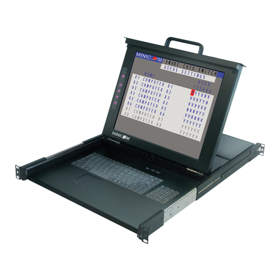
- Page 1 SmartRack 116 - Quick Start Guide 1111 W. 35th Street, Chicago, IL 60609 USA www.tripplite.com/support Copyright ©2012 Tripp Lite. All rights reserved.
- Page 2 SMARTRACK 116 SWITCH 1 . I nt r od u c t i on To take advantage of the full range of features, we recommend you read the softcopy User Guide after performing the Quick Start procedure. It’s in PDF format on the supplied CD or on our website www.minicom.com in the Support section.
-
Page 3: Hardware Kit Contents
USER GUIDE 2.1 Hardware kit contents Rail with front and rear bracket x 2, for rack depth of 614 ~ 800 mm. Right and left sides are different. Long bracket x 2. (For increased rack depth of 905 ~ 990mm) Medium bracket x 2. -
Page 4: Pre-Installation Guidelines
SMARTRACK 116 SWITCH Screws x4 Keys x 2. 2.2 Pre-installation guidelines Switch off all computers Place cables away from fluorescent lights, air conditioners, and machines that are likely to generate electrical noise Ensure that the maximum distance between each computer and the SmartRack 116 does not exceed 30m/100ft 2.3 Connecting to a rack Note! For increased rack depth of between 800 ~ 990mm, first change the... - Page 5 USER GUIDE 3. Adjust the rear bracket to fit your cabinet, see below. Figure 3 Adjusting the bracket 4. Install the front and rear bracket onto the cabinet, see figure below. Figure 4 Installing front and rear bracket on cabinet 5.
- Page 6 SMARTRACK 116 SWITCH 7. Slide the SmartRack console between the rails as shown below. Figure 6 Sliding the SmartRack between the rails 8. Unlock and pull both left and right rail–lock switches together – see below – and push the console all the way into the rack. Figure 7 Rail–lock switch 9.
-
Page 7: Using The Medium Or Longer Bracket
USER GUIDE The console now sits snugly in the rack, see Figure 9. Figure 9 Console in the rack 2.4 Using the medium or longer bracket For a rack depth of 800 ~ 905mm, use the medium bracket. For a rack depth of 905 ~ 990mm, use the longer bracket. -
Page 8: Connecting The Kvm Switch 116
SMARTRACK 116 SWITCH 2. Take the rear bracket out, see below. Figure 12 Taking the rear bracket out 3. Insert the medium/long bracket into the rail then adjust the bracket to fit your cabinet. 4. Tighten at least 2~3 screws along the length you need. Note! For medium bracket use the round screws , and for the long bracket use the flat screws . - Page 9 USER GUIDE 2. Slide the Switch 116 into the rail and into the back of the SmartRack console until you hear a click. See the figure below. Figure 15 Slide switch into back of SmartRack 3. Secure the Switch 116 to the rail by inserting the thumbscrews through the bracket and into the rail and tightening them, see Figure 16.
-
Page 10: The Kvm Switch 116
SMARTRACK 116 SWITCH 3 . T h e S m a r t Ra c k 11 6 s ys t e m c on f i g ur a t i o n You connect servers to the SmartRack 116 via ROCs. Figure 17 illustrates the basic configuration of the 116 Switch. -
Page 11: Connecting Rocs To Servers
USER GUIDE 3.2 Connecting ROCs to servers Each computer/server is directly connected to the Switch 116 via the appropriate ROC using CAT5 cable in a star configuration. No external power is needed at the remote ROCs. The ROCs draw their power from the computer’s keyboard port (ROC PS/2) or from the USB port (ROC USB). -
Page 12: The Keyboard Hotkeys
SMARTRACK 116 SWITCH 4 . O pe r a t i n g t he S m a r t Ra c k 11 6 s ys t e m Switch between the connected computers by either Keyboard hotkeys ... -
Page 13: Navigating The Osd
USER GUIDE 4.2.1 Navigating the OSD To navigate up and down use the Up and Down arrow keys. To jump from one column to the next (when relevant) use the Tab key. To exit the OSD or return to a previous window within the OSD press Esc. 4.2.2 Selecting a computer To select a computer: 1. - Page 14 SMARTRACK 116 SWITCH 4.2.4 Tuning – F5 You can tune the image of any remote computer screen from the Select Computer window. To adjust the screen image: 1. Navigate to the remote computer you wish to adjust. 2. Press F5. The screen image of the selected computer appears, together with the Image Tuning label.