Advertisement
Quick Links
Download this manual
See also:
User Manual
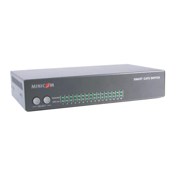
Smart CAT5 Switch - 108 and 116
1. Introduction
To take advantage of the full range of features, we recommend you read the softcopy
To take advantage of the full range of features, we recommend you read the softcopy
User Guide after performing the Quick Start procedure. It's in PDF format on the
User Guide after performing the Quick Start procedure. It's in PDF format on the
supplied CD or on our website www.minicom.com in the Support section.
Access and control multiple multi-platform computers from one Keyboard Video
Mouse (KVM) console with the Smart CAT5 Switch (Smart CAT5) system. The Smart
Mouse (KVM) console with the Smart CAT5 Switch (Smart CAT5) system. The Smart
CAT5 comes in 108 and 116 models. Connect up to 8 computers to the 108 model, and
CAT5 comes in 108 and 116 models. Connect up to 8 computers to the 108 model, and
up to 16 to the 116 model.
2. System components
The Smart CAT5 system consists of:
Smart CAT5 Switch 108 or 116
RICC on Cable (ROCS) - PS/2, USB
CAT5 cables (1.5m provided)
RS232 Serial cable
Rack mounts for the Smart CAT5
Quick Start Guide
platform computers from one Keyboard Video
and 116
upport section.
1111 W. 35th Street, Chicago, IL 60609 USA
1111 W. 35th Street, Chicago, IL 60609 USA
www.tripplite.com/support
www.tripplite.com/support
Copyright ©2012 Tripp Lite. All rights reserved.
©2012 Tripp Lite. All rights reserved.
Advertisement

Related Manuals for Tripp Lite 108


Summary of Contents for Tripp Lite 108
-
Page 1: Quick Start Guide
RS232 Serial cable Rack mounts for the Smart CAT5 1111 W. 35th Street, Chicago, IL 60609 USA 1111 W. 35th Street, Chicago, IL 60609 USA www.tripplite.com/support www.tripplite.com/support Copyright ©2012 Tripp Lite. All rights reserved. ©2012 Tripp Lite. All rights reserved. -
Page 2: The Smart Cat5 System Configuration
SMART CAT5 SWITCH – 108/116 3. The Smart CAT5 system configuration Figure 1 illustrates the basic configuration of the Smart CAT5 system. Workstation SMART CAT5 SWITCH 116 www.minicom.com COMPUTER POWER 100-240 VAC 50/60 Hz To servers RoC/RICCs to servers Figure 1 Smart CAT5 system configuration 4. -
Page 3: Connecting The Smart Cat5 System
QUICK START GUIDE 6. Connecting the Smart CAT5 system Each computer / server is directly connected to the Smart CAT5 via the appropriate ROC using CAT5 cable in a star configuration. No external power is needed at the remote ROCs. The ROCs draw their power from the computer’s keyboard port (ROC PS/2) or from the USB port (ROC USB). -
Page 4: The Osd
SMART CAT5 SWITCH – 108/116 Switch between the connected computers by either The front panel Select buttons Keyboard hotkeys - To switch to the next computer forwards press Shift then, +. Release Shift, before pressing +. To switch to the next computer backwards press Shift then, -.