
Related Manuals for Tripp Lite B021-02R-17


Summary of Contents for Tripp Lite B021-02R-17
-
Page 1: Table Of Contents
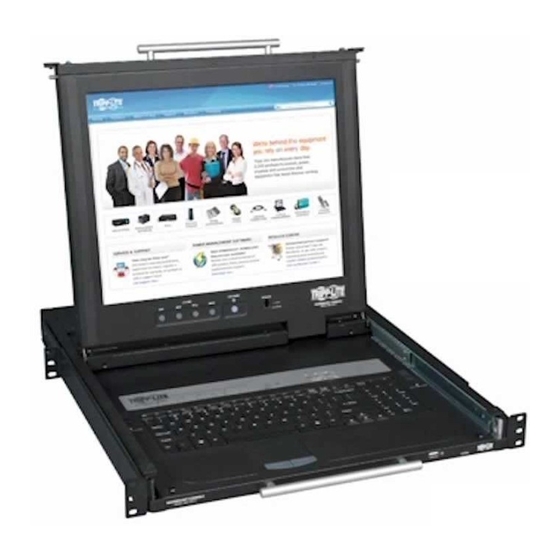
Owner’s Manual 17-in. USB/ PS2 Dual Rail Console Model: B021-02R-17 Package Contents Features System Requirements Components Hardware Setup Operation Firmware Upgrade Appendix Specifications 1111 W. 35th Street, Chicago, IL 60609 USA www.tripplite.com/support Copyright © 2010 Tripp Lite. All rights reserved. -
Page 2: Package Contents
Package Contents: • B021-02R-17 17-in. USB/PS2 Dual Rail Console • Rackmount Hardware • USB/PS2 Console Cable Kit • RJ11 to DB9 Firmware Upgrade Cable • C13 to 5-15P Power Cord • Grounding Wire • Owner’s Manual CD Features • I ntegrated 17-in. LCD display, 99-key keyboard and touchpad in a 1U rackmountable housing. -
Page 3: Components
Components Front View LCD Module Handle – Pull to slide the LCD Keyboard Release Catch – When fully module out, push to slide the LCD module in. extended, the keyboard module locks into place. Pulling the release catches on both LCD Module – See LCD Module on page 5 sides of the keyboard panel will allow you to for details. slide the module back into the rack. Keyboard Module – See Keyboard Module on LCD Release Catch – When fully extended, page 4 for details. the LCD module locks into place. Pulling the release catches on both sides of the console Keyboard Module Handle – Pull to slide the will allow you to slide the module back into keyboard module out, push to slide the the rack. - Page 4 Components continued Keyboard Module Keyboard Release Catch – When fully extended, the keyboard module locks into place. Pulling the release catches on both sides of the keyboard panel will allow you to slide the module back into the rack. Reset Button – Pressing the reset button will perform a system reset. Note: The reset button is semi-recessed and should be pushed with a thin object, such as a paper clip. Lock LEDs – The [Num Lock], [Scroll Lock] and [Caps Lock] keyboard LEDs are located here. Keyboard Touchpad External Mouse Port – A USB port is provided for convenient connection of an external mouse.
- Page 5 Power Switch – This is a standard power switch that turns the console off and on. External Console Ports – A HD15 Female, MiniDin6 Female (x2) and USB A Female (x2) ports are available for connection of an external console. Note: An additional USB A Female port is located on the front of the keyboard module for convenient connection of an external mouse. Computer Port – The included USB/PS2 combo KVM cable kit connects to the console here. Grounding Terminal – The included grounding wire connects to the console here. CONSOLE PS/2- USB RACKMOUNT CONSOLE MODEL: B021-02R-17 100- 240V~ ,1A,50/ 60H z...
-
Page 6: Hardware Setup
Hardware Setup General Safety Instructions • R ead all of these instructions. Save them for future reference. • F ollow all warnings and instructions marked on the device. • T his equipment is not recommended for use in life support applications where equipment failure can reasonably be expected to cause failure in life support equipment or to significantly affect its safety or effectiveness. Do not use this equipment in the presence of a flammable anesthetic mixture with air, oxygen or nitrous oxide. • T his device is designed for IT power distribution systems with up to 230V phase-to-phase voltage. • D o not place the device on any unstable surface (cart, stand, table, etc.). If the device falls, serious damage will result. • D o not use the device near water. • D o not place the device near or above radiators or heat registers. - Page 7 Hardware Setup continued • I f any of the following conditions occur, unplug the device from the wall outlet and bring it to qualified service personnel for repair. The power cord or plug has become damaged or frayed. Liquid has been spilled into the device. The device has been exposed to rain or water. The device has been dropped or the cabinet has been damaged. The device exhibits a distinct change in performance, indicating a need for service. The device does not operate normally when the operating instructions are followed. • A djust only those controls that are covered in the operating instructions. Improper adjustment of other controls may result in damage that will require extensive repair work by a qualified technician. • D o not connect the RJ11 connector marked “UPGRADE” to a public telecommunications network Rackmounting Safety Instructions • B efore working on the rack, make sure that the stabilizers are secured to the rack, extended to the floor, and that the full weight of the rack rests on the floor. Install front and side stabilizers on a single rack or front stabilizers for joined multiple racks before working on the rack.
- Page 8 Hardware Setup continued Rackmounting The B021-02R-17 is designed for mounting in a 1U rack system. The various mounting options are explained in the sections that follow. Standard 4-Post Rackmounting The standard rackmounting brackets that come attached to the B021-02R-17 allow the unit to be installed in standard 1U racks by a single individual. Slide out the rear mounting brackets from the console and mount both brackets (separate from the console) to the inside rear of a standard 1U rack system using user-supplied screws. Take the console and gently slide it into the two rear-mounted brackets in the rack and secure the console in place by inserting user-supplied screws. 2-Post Rackmounting The B021-02R-17 can also be mounted in a 2-post rack using the optional 2-Post Rackmount Kit (Model: B019-000). The mounting hardware allows for the console to be opened with the drawer in any position. The kit provides added stability and prevents the console frame from twisting. See the B019-000 Owner's Manual for detailed mounting instructions. Installation Turn off the power to all devices that are being connected. You must unplug the power cord of any computer that has the Keyboard Power On function. Connect the Yellow HD18 connector on the included KVM cable kit to the computer port on the back of the unit. Connect the Blue HD15 connector on the included KVM cable kit to the HD15 port on your computer or KVM. Connect the USB connector or PS/2 connectors on the included KVM cable kit to a USB port or the PS/2 ports on your computer or KVM. If you are installing an external console, connect your external VGA monitor and USB or PS/2 keyboard and mouse to the external console ports on the unit. Connect the included power cord from the console to a Tripp Lite Surge Suppressor, Power Distribution Unit (PDU) or Uninterruptible Power Supply (UPS).
-
Page 9: Operation
Operation This section covers the operation of the console; opening/closing the LCD and Keyboard modules, hot plugging, hotkeys, etc. Opening and Closing the Console Modules The B021-02R-17 features dual rail technology, which allows the LCD module to slide independently of the keyboard module, letting you slide the keyboard module back into the rack while leaving the LCD module open for monitoring the connected computer or KVM. This section describes how to open and close each module. Note: The maximum load bearing capacity of the keyboard module is 66 lbs. (30 kg.). Do not lean your body weight on the keyboard module, or place heavy objects on it. Opening the Console Modules The console modules can be opened together or separately. To open the console modules, simply slide the console release tabs inward, and then slide the modules out of the rack until they lock into place. Release Catch The LCD module extends further than the keyboard module, so if you open both at the same time, pull them until the keyboard module locks into place, and then pull the LCD module separately until it locks into place. When the LCD module is locked into place, rotate it all the way back so that the LCD is displayed. - Page 10 Operation continued Closing the Console Modules To close the keyboard module, slide the release catches on both sides of the unit forward and push the keyboard module into the rack. You can let go of the release catches once the unit has been pushed forward, and slide the unit the rest of the way into the rack. To close the LCD module, rotate the display all the way down, and then pull the release catches on each side of the unit forward. Push the module all the way into the rack.
- Page 11 Operation continued Hot-Swapping The B021-02R-17 supports hot-swapping, allowing components to be connected and disconnected without having to shut down the console. Hotkey Commands The hotkey commands in the table below are available for controlling the console. Each key in the hotkey command must be pressed one at a time. Hotkey Description [Ctrl], [Alt], [Shift], [p], [c], This is the default computer setting for the console. It should be selected [Enter] when connecting anything other than a Sun computer.
-
Page 12: Firmware Upgrade
Firmware Upgrade As firmware upgrade files become available, they can be found at www.tripplite.com/support. A single upgrade file contains both the Windows-based Firmware Upgrade Utility and the Firmware Upgrade file. To upgrade the firmware of your console, follow the steps below: From a computer that is not connected to your console, go to www.tripplite.com/support to obtain the firmware upgrade file, and save it to your computer. Using the firmware upgrade cable that came with the unit, connect the cable from the RJ11 firmware upgrade port on the LCD panel of the console to a DB9 Serial port on the computer you saved the firmware to. Invoke Firmware Upgrade Mode using the hotkey command mentioned in the table on page 11. ([Ctrl], [Alt], [Shift], [u], [p], [g], [r], [a], [d], [e], [Enter]) The firmware upgrade recovery switch (see page 5 for details) must be in the Normal position to use this hotkey command. You can also enter firmware upgrade mode using the steps outlined in the Firmware Upgrade Recovery section on page 13. When in firmware upgrade mode, the screen will be black and the [Num Lock], [Caps Lock] and [Scroll Lock] LEDs will flash on and off. On the computer the firmware upgrade file is saved to, run the Firmware Upgrade Utility file by double-clicking on it or by opening up a command line and typing in the path to it. After reading the license agreement, click on the I Agree option and click Next. The Firmware Upgrade Utility main screen appears and the utility searches for and displays all upgradeable devices. I f you want the Firmware Upgrade Utility to check the firmware version to see if it is older/newer than the firmware upgrade file, check the Check Firmware Version box in the lower-left corner of the screen. If you want the Firmware Upgrade... -
Page 13: Appendix
Firmware Upgrade continued Firmware Upgrade Failed In the event of an upgrade failure, the Status Messages panel will display a message that says the upgrade failed, and a dialog box will appear asking if you wish to retry the firmware upgrade. Click Yes to retry the firmware upgrade, or No to cancel and proceed to a firmware upgrade recovery. Firmware Upgrade Recovery If you are unable to successfully upgrade your firmware, you may not be able to operate the console. If this is the case, follow the procedure below to recover from a firmware upgrade failure. Slide the firmware upgrade recovery switch on the LCD panel of the unit to the Recover position. Power off and restart the KVM switch. Connect the included firmware upgrade cable from the RJ11 firmware upgrade port on the LCD panel of the switch to a DB9 Serial port on the computer you saved the firmware to. Proceed with the firmware upgrade starting with step 4 in the Firmware Upgrade section. (See page 12 for details.) When the upgrade is complete, power off the console. Slide the firmware upgrade recovery switch to the Normal position and then power on the console. Appendix Sun Keyboard Emulation The PC compatible keyboard can emulate the functions of the Sun keyboard using the PC keystrokes in the table below. Note: When more than one key is required on the PC Keyboard to emulate the Sun keyboard, press and release the first key, and then press and release the second key. PC Keyboard Sun Keyboard [Ctrl], [T] [Stop] [Ctrl], [F2]... -
Page 14: Specifications
Specifications Feature Specification Form Factor 1U Rackmount HD15 Female, USB A Female (x2), Console Port MiniDIN6 Female (x2) Computer/KVM Monitor Connection HD15 Male (via included KVM cable kit) USB A Male (x1), Computer/KVM Keyboard and Mouse Connectors MiniDIN6 Male (x2) (via included KVM cable kit) Power Jack IEC-320-C14 I/P Rating... -
Page 15: Limited Warranty
For the purpose of regulatory compliance certifications and identification, your Tripp Lite product has been assigned a unique series number. The series number can be found on the product nameplate label, along with all required approval markings and information. When requesting compliance information for this product, always refer to the series number. The series number should not be confused with the marking name or model number of the product. WEEE Compliance Information for Tripp Lite Customers and Recyclers (European Union) Under the Waste Electrical and Electronic Equipment (WEEE) Directive and implementing regulations, when customers buy new electrical and electronic equipment from Tripp Lite they are entitled to: • S end old equipment for recycling on a one-for-one, like-for-like basis (this varies depending on the country)