Tripp Lite 116 User Manual
Hide thumbs
Also See for 116:
- Quick start manual (4 pages) ,
- Quick start manual (15 pages) ,
- User manual (38 pages)

Related Manuals for Tripp Lite 116


Summary of Contents for Tripp Lite 116
-
Page 1: Smart Cat5 Switch
Smart CAT5 Switch 108 and 116 User Guide 1111 W. 35th Street, Chicago, IL 60609 USA www.tripplite.com/support Copyright ©2012 Tripp Lite. All rights reserved. -
Page 2: Table Of Contents
SMART CAT5 SWITCH – 108/116 Table of Contents 1. Welcome ..........................4 2. Introduction........................... 5 2.1 Features............................. 5 2.2 System components ......................... 5 2.3 Compatibility ............................. 6 2.4 The Smart CAT5 system configuration.................... 6 2.5 The Smart CAT5 models........................7 2.6 Pre-installation guidelines........................ - Page 3 USER GUIDE 4.2.9 Security ............................22 4.2.10 The OSD HELP window – F1..................... 23 4.2.11 Scanning computers– F4 ......................24 4.2.12 Tuning – F5 ..........................24 4.2.13 Moving the label – F6......................... 24 4.2.14 Sending monitor emulation information to ROC/RICCs – F10 ............ 24 4.2.14.1 Updating the DDC information ....................
- Page 4 SMART CAT5 SWITCH – 108/116 6.7.2 Getting the current status......................38 6.7.3 Communication Error message....................38 6.7.4 Electricity failure........................... 39 7. RICC SUN keyboard emulation...................40 8. USB / SUN Combo keys ......................41 9. Technical specifications .....................42 9.1 Safety............................... 43 9.2 WEEE compliance........................... 43...
-
Page 5: Welcome
USER GUIDE 1 . We l c om e Thank you for buying the Smart CAT5 Switch system. This system is produced by Minicom Advanced Systems Limited. Technical precautions This equipment generates radio frequency energy and if not installed in accordance with the manufacturer’s instructions, may cause radio frequency interference. -
Page 6: Introduction
Access and control multiple multi-platform computers from one Keyboard Video Mouse (KVM) console with the Smart CAT5 Switch (Smart CAT5) system. The Smart CAT5 comes in 108 and 116 models. Connect up to 8 computers to the 108 model, and up to 16 to the 116 model. -
Page 7: Compatibility
DOS, Windows, LINUX, UNIX, MAC and all other major operating systems 2.4 The Smart CAT5 system configuration Figure 1 illustrates the basic configuration of the Smart CAT5 system. Workstation SMART CAT5 SWITCH 116 www.minicom.com COMPUTER POWER 100-240 VAC 50/60 Hz... -
Page 8: The Smart Cat5 Models
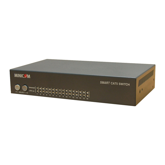
SMART CAT5 SWITCH – 108/116 2.5 The Smart CAT5 models Figure 2 illustrates the front panel of the Smart CAT5 116 model. The 108 model is the same but with only 8 columns of LEDs. MINICOM SMART CAT5 SWITCH Selected... -
Page 9: Connecting The Smart Cat5 System
USER GUIDE 3 . C o n ne c t i n g t he S m a r t C AT 5 s ys t e m Each computer/ server is directly connected to the Smart CAT5 via the appropriate ROC or RICC using CAT5 cable in a star configuration. -
Page 10: Connecting A Roc/Ricc Usb
SMART CAT5 SWITCH – 108/116 NetServer tc2100 To Keyboard port To Mouse port RICC PS/2 To Video port SCSI CAT5 cable to Smart PCI 33Mx32b CAT5 Computer port PCI 33Mx32b PCI 33Mx32b PCI 33Mx32b Figure 6 RICC PS/2 connections 3.2 Connecting a ROC/RICC USB The ROC/RICC USB supports Windows 98 SE and later, MAC, SUN, SGI and all modern Linux distributions. -
Page 11: Connecting A Ricc Sun
USER GUIDE 3.3 Connecting a RICC SUN Figure 8 illustrates the RICC SUN and its connections. To connect the RICC SUN: 1. Connect the Screen connector to the computer’s Video port. 2. Connect the Keyboard connector to the computer’s Keyboard port. To Keyboard To Video port Port... -
Page 12: Avoiding General Rack Mounting Problems
SMART CAT5 SWITCH – 108/116 3.6.1 Avoiding general rack mounting problems Elevated operating ambient temperature The operating ambient temperature of the rack environment may be greater than the room ambient when installing into a closed or multi-unit rack assembly. So install the equipment in an environment compatible with the maximum rated ambient temperature. -
Page 13: Rack Mounting The Riccs
USER GUIDE Screw the bracket into the side of the unit Screw to the rack here Figure 10 Connecting the L-shaped bracket 3.6.3 Rack mounting the RICCs You can attach the RICCs to a server rack or computer using the Velcro strips provided. - Page 14 SMART CAT5 SWITCH – 108/116 With the Smart CAT5 116 model, connect up to up to 256 computers through cascading. A lower level Switch must have a different hotkey to display its OSD than a higher level switch. Changing the OSD display hotkey is explained on page 18 below.
-
Page 15: Operating The Smart Cat5 System
USER GUIDE 4 . O pe r a t i n g t he S m a r t C AT 5 s ys t e m Switch between the connected computers by either The front panel Select buttons ... -
Page 16: Navigating The Osd
SMART CAT5 SWITCH – 108/116 Port number appears here C=Computer Instruction keys Figure 13 OSD Main window 4.2.1 Navigating the OSD To navigate up and down use the Up and Down arrow keys. To jump from one column to the next (when relevant) use the Tab key. -
Page 17: The General Settings
USER GUIDE Figure 14 Settings window Note! When the OSD is password protected (explained below) only the Administrator has access to the F2 settings window. 4.2.4 The General settings With the GENERAL line highlighted, press Enter. The General settings window appears see Figure 15. -
Page 18: Administrator (Status A)
SMART CAT5 SWITCH – 108/116 4.2.4.2 Administrator (Status A) The Administrator can: Set and modify all Passwords and security profiles Fully access any computer Use all OSD functions 4.2.4.3 Supervisor (Status S) The Supervisor can: Fully access any computer ... -
Page 19: Displaying The Osd Of Cascaded Switches
USER GUIDE 4.2.4.6 Displaying the OSD of cascaded switches When you have cascaded Smart CAT5 switches, a lower level Switch must have a different OSD display hotkey than a higher level switch. (See page 12.) The hotkeys can be any of the following: ... -
Page 20: Changing The Keyboard Language
SMART CAT5 SWITCH – 108/116 To change the Serial port setting: 1. Navigate to the Serial port line. 2. Toggle between the options using the Spacebar. 4.2.4.9 Changing the Keyboard language In the OSD the names of the computers can be written in 3 different languages –... -
Page 21: Editing The Computer Name
USER GUIDE 4.2.6.1 Editing the computer name In this window you can edit the computer names with up to 15 characters. When you have a cascaded CAT5 KVM Switch connected to a Computer port give the switch a distinct name. See Figure 16. To erase a character: Select it and press the Spacebar. -
Page 22: Scan (Scn) - Label (Lbl) - Time Out (T/O)
SMART CAT5 SWITCH – 108/116 Figure 17 Time settings window 4.2.7.1 Scan (SCN) - Label (LBL) - Time out (T/O) SCN - In the SCN column, change the scan period. LBL - In the LBL column, change the display period of the OSD label showing which computer is currently accessed. -
Page 23: Security
USER GUIDE Figure 18 Users settings window There are 3 different access levels. These are: Y – Full access to a particular computer. Plus access to the F4, F5 and F6 OSD functions V –Viewing access only, to a particular computer (No keyboard/mouse functionality) ... -
Page 24: The Osd Help Window - F1
SMART CAT5 SWITCH – 108/116 Figure 19 Security settings window The ‘T’ column on the right hand side stands for Type of password. There can only be 1 Administrator password, 1 Supervisor password, and 6 User passwords. To change a user name or password: 1. -
Page 25: Scanning Computers- F4
USER GUIDE 4.2.11 Scanning computers– F4 Where necessary adjust the scan time in the Time Settings window, see above. To activate scanning: 1. Press Shift twice to open the OSD. 2. Press F4. Your screen displays each active computer sequentially, with the Scan label appearing in the top left corner. -
Page 26: Updating The Ddc Information
SMART CAT5 SWITCH – 108/116 Input the DDC information of the monitor connected to the Smart CAT5 switch into the memories of all connected ROC/RICCs when first installing system. To input the DDC information: 1. Disconnect the Video cable of all ROC/RICCs from the computers. -
Page 27: Using The Control Software
Free Serial port 5.2 Connecting the RS232 Serial cable To run the software, connect the RS232 Serial cable to the computer containing the software, and to the Smart CAT5. See the figure below. SMART CAT5 SWITCH 116 www.minicom.com COMPUTER POWER... -
Page 28: Installing And Running The Control Software
SMART CAT5 SWITCH – 108/116 5.3 Installing and running the Control software Note! The system must be fully connected BEFORE running the Control software. Failure to first connect the system will lead to the software working in demo mode. 1. Download the software from www.minicom.com... -
Page 29: Computer Icons
USER GUIDE 5.3.2 Computer icons Icon Meaning Computer is connected and switched on Computer is switched off or unconnected Computer that you are presently connected to Connected and switched on computer with a Local Workstation attached and presently being used locally. After remaining idle for the Timeout period, it changes to yellow. -
Page 30: Selecting A Computer
SMART CAT5 SWITCH – 108/116 5.3.5 Selecting a computer To select a computer: Click on the computers icon. The system switches to that computer. The connected icon appears with a red background . Control and monitor the selected computer from the keyboard and mouse connected to the Smart Switch. -
Page 31: The Edit Menu
USER GUIDE 5.3.11 The Edit menu You can edit all OSD fields. Edit the following from the Edit menu. Logo Passwords Settings 5.3.12 Logo and Passwords You can edit the logo that appears at the top of the OSD window. You can also edit the names and passwords for the Administrator, Supervisor and 6 Users. -
Page 32: Single Computer Settings
SMART CAT5 SWITCH – 108/116 Here you can edit all the data that can be edited in the OSD. This includes: Scan times, Timeout, Confirmation label display time, Keyboard type/mode, User access, Password mode, Autoskip mode, and Switch/System hotkey. These features are explained in the OSD section of this Appendix. -
Page 33: Password Protection
USER GUIDE 5.4 Password protection When the Smart CAT5 system is password protected, the Control software behaves in exactly the same way as the OSD. You must type in the required password to access the Control software. The access you gain depends on the security status – exactly as with the OSD. -
Page 34: Upgrading The Smart Cat5 Firmware
SMART CAT5 SWITCH – 108/116 6 . U p gr a di n g t he S m a r t C AT 5 f i r mw a r e With the Smart CAT5 Update software program you can upgrade the firmware for the: ... -
Page 35: Installing The Software
USER GUIDE 6.4 Installing the software Download the Update software and install it on your computer. 6.4.1 Connecting the RS232 Serial cable To run the software, connect the RS232 Serial cable to the computer containing the Update software, and to the Smart CAT5 Switch. See page 26. 6.5 Starting and configuring the Smart CAT5 Update 1. -
Page 36: Verifying The Version Numbers
SMART CAT5 SWITCH – 108/116 Button or Box Function Cancels selected function System time Displays device status Name of Update file 2. To change the Com Port from the Options menu choose Com Port. The Com Port Dialog box appears. See Figure 29. -
Page 37: Smart Cat5 Manager Version Number
USER GUIDE 6.5.1.2 Smart CAT5 Manager version number To verify the Smart CAT5 version number: In the Switch Unit box, check the Smart CAT5 Manager option. Click . The firmware version number appears in the Switch Unit box. Click . The hardware version number appears in the Switch Unit box. -
Page 38: Restoring Factory Settings
SMART CAT5 SWITCH – 108/116 Figure 30 Open box Open the file. Click Start. The Smart CAT5 Switch Update flashes the firmware. On completion the firmware version number appears. Check that the updated version number is correct by pressing 6.6 Restoring factory settings You can restore the OSD to the factory settings from the Update software. -
Page 39: Resetting The Units
USER GUIDE 6.7.1 Resetting the units Resetting can be done from the Update software or from the Smart CAT5 switch. Resetting through the Update software Reset the software for the Smart CAT5 Manager or ROC/RICCs when for example the unit hangs or when the mouse fails to work properly. Resetting is done via the Serial port, and avoids the need to shut down the computer. -
Page 40: Electricity Failure
SMART CAT5 SWITCH – 108/116 6.7.4 Electricity failure When the electricity fails while updating the Smart CAT5 firmware, do the following: If the electricity fails during the firmware update of the Switch, a Communication Error message appears. Simply resume the firmware update by opening the folder that contains the firmware update file and continue from there. -
Page 41: Ricc Sun Keyboard Emulation
USER GUIDE 7 . R I C C S U N k e yb o a r d e m ul a t i on By default the RICC SUN supports US English keyboard emulation. It also supports German and Swiss German keyboard emulation. You can download the appropriate keyboard emulation firmware from our website www.minicom.com in the Support... -
Page 42: Usb / Sun Combo Keys
SMART CAT5 SWITCH – 108/116 8 . U S B / S UN C om b o k e ys The connected PS/2 keyboard does not have a special SUN keypad to perform special functions in the SUN Operating System environment. So when a ROC/RICC USB or SUN is connected to a SUN computer, the ROC/RICC emulates these SUN keys using a set of key combinations called Combo keys. -
Page 43: Technical Specifications
215.0 x 122.0 x 41.5mm / 8.46 x 4.80 x 1.63in port Weight – 108/116 Product – 920g / 2lbs Shipping – 1.87Kg / 4.1lbs Power supply – 108/116 Internal switching 85-260 VAC 50 / 60 Hz Connections System RJ45... -
Page 44: Safety
SMART CAT5 SWITCH – 108/116 9.1 Safety The device must only be opened by an authorized Minicom technician. Disconnect device from AC mains before service operation! 9.2 WEEE compliance WEEE Information for Minicom Customers and Recyclers Under the Waste Electrical and Electronic Equipment (WEEE) Directive and... - Page 45 USER GUIDE 201204196 • 933193...