Table of Contents
Advertisement
Quick Links
Owner's Manual
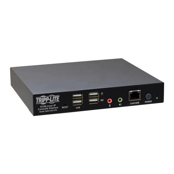
HDMI KVM over IP Remote
User Console Station
WARRANTY REGISTRATION
Register your product today and be
automatically entered to win an ISOBAR
surge protector in our monthly drawing!
tripplite.com/warranty
Model: B064-000-STN
1111 W. 35th Street, Chicago, IL 60609 USA • tripplite.com/support
Copyright © 2020 Tripp Lite. All rights reserved.
®
1
Advertisement
Table of Contents

Related Manuals for Tripp Lite B064-000-STN


Summary of Contents for Tripp Lite B064-000-STN
- Page 1 WARRANTY REGISTRATION Register your product today and be automatically entered to win an ISOBAR ® surge protector in our monthly drawing! tripplite.com/warranty 1111 W. 35th Street, Chicago, IL 60609 USA • tripplite.com/support Copyright © 2020 Tripp Lite. All rights reserved.
-
Page 2: Table Of Contents
Table of Contents 1. Overview 5. System Configuration 1.1 Features 5.1 User Management 5.1.1 Users and Groups 1.2 Package Contents 5.1.1.1 Add User 1.3 Optional Accessories 5.1.1.2 Copy User 1.4 System Requirements 5.1.1.3 Modify User 1.5 Introduction 5.1.1.4 Delete User 2. - Page 3 Table of Contents 5.3 Maintenance 6.4 Further Configuration 5.3.1 Upgrade Main Firmware 6.4.1 Virtual Media 5.3.2 Firmware Upgrade 6.4.2 Message Board Recovery 6.4.2.1 Buttons 5.3.3 Backup/Restore 6.4.2.2 Message Display 5.3.3.1 Backup Panel 5.3.3.2 Restore 6.4.2.3 Compose Panel 5.3.4 Push/Pull Configuration 6.4.2.4 User List Panel 5.3.4.1 Pull Configuration 6.4.3 Mouse Sync Mode...
-
Page 4: Overview
• External Power Supply (100V-240V) with C13 to NEMA 5-15P Power Cord 1.3 Optional Accessories • P569-Series High Speed HDMI Cables 1.4 System Requirements • Tripp Lite’s B064-IPG-Series KVM over IP with Firmware Version of V1.1.102 or Above • USB Mouse/Keyboard & HDMI Monitor... -
Page 5: Introduction
1. Overview 1.5 Introduction Front Panel: Reset Switch Cascade Port USB 2.0 Peripheral Ports Power Button (Press once to enter Standby Mode, press again to power on the unit) USB Keyboard/Mouse Ports Power LED (Power ON: Blue; Standby: Orange) Microphone and Speaker Ports Rear Panel: Ground Terminal COM (RS-232) Port... -
Page 6: Setup
2. Setup 2.1 Mounting Instructions The B064-000-STN can be rack mounted or wall mounted. The following section will guide you through the proper steps. Rack Mounting The KVM over IP Console Station is designed to be mounted at the rear of a rack, where it occupies 0U to save space. - Page 7 2. Setup Wall Mounting 1. Remove two bottom screws on the unit. Use the screws to secure the mounting plate to the bottom of the unit. M3 x L5 (Countersunk Head) Figure 3: Secure Mounting Plate to Unit 2. With a user-supplied screw, use the mounting plate’s center screw hole to mount the unit to a wall. Figure 4: Mounting the Unit to a Wall...
-
Page 8: Installation
4. (Optional) Plug USB flash drives or devices into the peripheral USB ports on the front of the unit. 5. (Optional) To cascade an additional B064-000-STN unit, plug one end of a user-supplied Cat5e/6 Ethernet cable into the port labeled CASCADE on the first stage unit, then plug the other end of the Ethernet cable into the LAN port of a second stage B064-000-STN unit. -
Page 9: Operation
3.1 Logging In The B064-000-STN is a central control station used to monitor several or all of the B064-IPG-Series KVM switches in your network. A valid user name and password are required to log in (Figure 6). The default user name and password are administrator and password, respectively. -
Page 10: Dashboard
3. Operation 3.2 Dashboard Once you have successfully logged in, the HDMI KVM over IP Remote User Console Station interface dashboard appears. Note: The screenshot below depicts an administrator’s page. Depending on the user type and permissions, not all elements will appear. 1 2 3 4 5 No. -
Page 11: Dashboard Operation
3. Operation No. Name Description Available KVM over IP Switch Monitor Available KVM over IP Switch Monitor displays the available KVM over IP switch at a glance. Each monitor will consecutively rotate through the device’s connected ports. Tab Name Displays the tab name. Clicking the tab name will bring out an option “Reconnect All Devices”. - Page 12 3. Operation Monitor Unit Option Click the Menu icon to display the available options: Primary Display To display a port on the primary display: 1. Move the mouse over Primary Display and click to select the port. The selected port should now be on the primary display. Your keyboard and mouse can now also control the server connected to that port.
-
Page 13: Tab/Panel Array Display And Management
3. Operation If you wish to use the KVM over IP switch’s GUI, click “Open GUI”. Refer to the B064 KVM switch’s Owner’s Manual for GUI operation instructions. Disconnect Click “Disconnect” to disconnect from this KVM switch device. Reconnect Click “Reconnect” to reconnect to an offline KVM switch device. 3.4 Tab/Panel Array Display and Management Tab management allows users to separate KVM over IP switches currently being monitored into different groups or select which tab group is to be displayed on the dashboard. -
Page 14: Panel Array Options
3. Operation Tab Display Following is an example showing the KVM of IP switches in a tab displayed on the dashboard (tab1 selected): 3.4.2 Panel Array Options Click the Panel Array icon to display the panel array options: Option Description Panel Array Management This option allows you to add, delete or modify panel array (groups). - Page 15 3. Operation Panel Array Display Following is an example showing the ports of connected KVM over IP switches in a panel array displayed (array1 selected): Press the + icon to display more device ports (up to 64 ports) on a smaller scale. Press the - icon to display fewer device ports on a larger scale.
-
Page 16: Tab/Panel Array Management
3. Operation 3.4.3 Tab/Panel Array Management Click the Tab or Panel Array icon to show their corresponding options. Due to their similarity, tab management is used as the example below. Click “Tab Management” (or “Panel Array Management”) for the following page: This page allows you to add/edit/delete tabs. -
Page 17: Adding A Tab
3. Operation 3.4.4 Adding a Tab 1. To add a tab, click the + icon. A new window (Tab Device Configuration) will be displayed. 2. Enter a name for the new tab. 3. Click on the devices you wish to be in this tab group and click the >> button. -
Page 18: Adding Another Tab
3. Operation 4. Click the “OK” button when done. The tab will be shown: 3.4.5 Adding Another Tab To add another tab, click the + icon again and follow the steps outlined in section 3.4.4 Adding a Tab. 3.4.6 Editing a Tab To edit a tab, click the pen icon beside Tab Name. -
Page 19: Device Management
Device management enables users with administrative access/authority to add devices to or remove devices from the B064-000-STN. The KVM over IP Remote User Console Station can manage up to 256 KVM over IP switches and is able to display snapshots of up to 16 devices. -
Page 20: Search
4. Device Management 4.1.1 Search The rectangular field at the top is the search function. Enter the IP address of the device you want to search for to find that device. 4.1.2 Removing a Device To remove a device from the list, hover your mouse over the device. An X icon will be displayed. Click the X icon to remove the device. -
Page 21: Changing Connection Information
4. Device Management Hover your mouse over the search button (magnifying glass). A list of KVM control unit device(s) on the same local area network (LAN) will be shown: Select the desired device or enter an IP address of a known device; enter a user name and password, and click “Save” to add the device to the system. -
Page 22: System Configuration
5. System Configuration System configuration enables users with administrative authority to manage users or groups, display device information, configure network, advanced network management (ANMS) or security settings, or manage firmware upgrades, system backup/restore, push/pull configurations to or from other devices, access terminal, or reset the system to factory default settings. -
Page 23: Add User
5. System Configuration The KVM over IP Console Station supports two privilege categories determined by “User Types”. User types are selected during user creation. The descriptions are shown in the following table: User Types Role Administrator Access and manage devices. Manage users and groups. Configure the overall installation. Configure personal working environment. - Page 24 5. System Configuration 2. Enter the required information in the appropriate fields. A description of the required user fields is given in the following table: Field Description Username 1 to 32 characters are allowed depending on the Account Policy settings (refer to section 5.2.4.2 Account Policy).
-
Page 25: Copy User
5. System Configuration Click Back on the top right-hand corner of the configuration body or click Users in the left-hand side menu to return to the User Management page. The newly added user will appear in the configuration body. • The information/configuration body shows the user name, the description that was given when the account was created, whether the account is currently active or has been disabled and gives the option to modify or delete the user. -
Page 26: Managing (Assigning)
5. System Configuration 5.1.2 Managing (Assigning) Users and Groups There are two ways to assign users to groups: from the Users configuration page and from the Group configuration page. Note: Before you can assign users to groups, you must first create them. See Add User for details. 5.1.2.1 Using User Configuration Page Follow the steps below to go to the User’s configuration page: 1. -
Page 27: Using Group Configuration Page
5. System Configuration 5.1.2.2 Using Group Configuration Page Follow the steps below to go to the Group’s configuration page: 1. Click “Groups” under “User Management” in the left-hand side menu to bring up the configuration page. 2. Click the pen icon under the “Modify” column. 3. -
Page 28: Device Assignment
5. System Configuration 5.1.3 Device Assignment This function assigns access rights to users or groups and can be achieved from Device configuration page. Administrators can assign users to a particular user’s privileges of an added KVM over IP Switch and access ports. 5.1.3.1 Using Device Configuration Page Follow the steps below to go to the User’s configuration page: 1. - Page 29 5. System Configuration Device Group Config • After selecting a device, the Available column (left column) lists the available groups (of the device). • The Selected column (right column) shows the selected groups (of the device). • Click the >> or << icon buttons to shift between Available and Selected. •...
-
Page 30: Device Management
5. System Configuration 5.2 Device Management This screen shows device information and allows you to configure network, ANMS and security settings. Note: Whenever a new setting is saved, the system will reboot. 5.2.1 Device Information Click “Device” under “Device Management” in the left-hand menu to bring up the information page. The Device Information page displays the name of the selected device, its firmware version, the FPGA (Field-Programmable- Gate-Array) and information about its network configuration. -
Page 31: Network
5. System Configuration 5.2.2 Network The Network page is used to specify the network environment. Click “Network” under “Device Management” in the left-hand menu to bring up the information page. Each of the elements on this page is described below. -
Page 32: Ip Installer
5. System Configuration 5.2.2.1 IP Installer The IP Installer is an external Windows-based utility for assigning IP addresses to the KVM over IP switch. Click one of the radio buttons to select Enable, View Only, or Disabled for the IP Installer utility. Notes: 1. -
Page 33: Advanced Network
5. System Configuration 5.2.3 ANMS (Advanced Network Management Settings) The ANMS page is used to set up login authentication and authorization management from external sources. Click “ANMS” under “Device Management” in the left-hand menu to bring up the information page. -
Page 34: Radius Settings
• For LDAP , the default port number is 389. Timeout Consult the AD/LDAP administrator to ascertain the appropriate entry for this field. For example, the entry might look like this: Admin DN ou=B064-008-01-IPG,dc=Tripp Lite,dc=com Admin Name Key in the administrator user name. Password Key in the administrator password. -
Page 35: Finishing Up
5. System Configuration LDAP attribute is required for complete setup. LDAP attribute can be retrieved from the GET command using the Terminal interface. Refer to section 5.3.5 Terminal for more details. On the AD/LDAP server, users can be authenticated with any of the following methods: •... -
Page 36: Login Failures
5. System Configuration 5.2.4.1 Login Failures For increased security, the Login Failures section allows administrators to set policies governing what happens when a user fails to log in successfully. To set the Login Failures policy, check the Enable checkbox (the default for Login Failures is enabled). -
Page 37: Maintenance
5. System Configuration 5.3 Maintenance The Maintenance function is used to upgrade firmware, backup and restore configuration and account information, push/pull configurations, send terminal commands, ping network devices and restore default values. 5.3.1 Upgrade Main Firmware As new versions of the firmware become available, they can be downloaded from tripplite.com/support. Click “Upgrade Main Firmware”... -
Page 38: Firmware Upgrade Recovery
5. System Configuration 5. Navigate to the directory that the new firmware file is in, click to select the file and click “Open”. 6. Click Upgrade Main Firmware to start the upgrade procedure. • If you enabled Check Main Firmware Version, the current firmware level is compared with that of the upgrade file. If the current version is equal to or higher than the upgrade version, a popup message appears to inform you of the situation and stops the upgrade procedure. -
Page 39: Backup
5. System Configuration 5.3.3.1 Backup To back up the device’s settings: Note: A USB flash drive is required to be connected to the console station to store the backup file. 1. (Optional) In the Password field, key in a password for the file. Notes: •... -
Page 40: Restore
5. System Configuration 5.3.3.2 Restore To restore previously saved settings: Note: A USB flash drive with the previously backed-up file is required to be connected to the console station for backup file retrieval. 1. Click the “Choose File” button for the file management window: 2. -
Page 41: Push/Pull Configuration
5. System Configuration 5.3.4 Push/Pull Configuration Push/Pull Configuration gives you the ability to deploy or retrieve your settings to or from other console stations. Click “Push cfg./Pull cfg.” under “Maintenance” in the left-hand side menu to bring out the information page. -
Page 42: Pull Configuration
5. System Configuration 5.3.4.1 Pull Configuration To pull (retrieve) a configuration to your console station: 1. Enter the device’s IP address or IPv6 Address you wish to retrieve the configuration from. Alternatively, you can hover your mouse over the magnifying glass to find a list of the devices on the same LAN and click the device’s IP or IPv6 address: 2. -
Page 43: Terminal
5. System Configuration 4. Click “Push” to deploy the information. The console station(s) will restart after successfully receiving the deployment information. 5.3.5 Terminal Terminal provides a command line to execute options using a terminal interface. Type a command in the window and hit [Enter] to execute it. -
Page 44: System Operation
5. System Configuration 5.3.6 System Operation The System Operation page lets you restore certain configuration changes that were made to the KVM over IP Console Station back to their original factory default values. 5.3.6.1 Reset Default Values Clicking this button undoes all Customization page changes that have been made to the KVM over IP Console Station and returns the parameters to the original factory default settings. -
Page 45: Quick User Configuration
5. System Configuration If you clear the check mark before exiting the page, the changes to the IP settings will be ignored and the original IP address settings will remain in effect. Note: Even though the changed IP settings are ignored, they still remain in the network settings fields. That means that the next time you open this page the Reset on Exit checkbox will automatically be enabled, and when the console station resets, the new IP settings that you thought you discarded will become the ones used by the console station. -
Page 46: Toolbar Interface
6. Toolbar Interface The KVM over IP Console Station’s interface provides a toolbar to help you with the remote control operations on the captured port. The toolbar is usually hidden. To bring up the toolbar, locate a down arrow symbol as shown: Hover your mouse over the down arrow symbol to bring up the toolbar. -
Page 47: Exit Remote Location
6. Toolbar Interface The meanings of the toolbar icons are explained in the following table: Option Description Video icon Brings up the video settings. See section 6.2 Video Settings for more details. Macros icon Provides access to three functions found in the Macros dialog box: Hotkeys, User Macros and System macros. See section 6.3 Macros for more details. -
Page 48: Video Settings
6. Toolbar Interface 6.2 Video Settings Click the Video icon on the toolbar to bring up the Video Settings dialog box. The options in the basic dialog box allow you to adjust the Screen Position, set Auto Sync, adjust Performance bar setting, Enhanced Text Mode, adjust Video Quality bar, and Set to Grayscale. -
Page 49: Macros
6. Toolbar Interface Option Description/Operation Enhanced Text Mode Check to enhance color and video quality, especially for text. Video Quality Drag the slider bar to adjust the overall Video Quality. The larger the value, the clearer the picture and the more video data goes through the network. Depending on the network bandwidth, a high value may adversely affect response time. -
Page 50: Hotkeys
6. Toolbar Interface 6.3.1 Hotkeys Various actions related to manipulating the remote server can be accomplished with hotkeys. The Hotkey Setup utility (accessed by clicking this icon) lets you configure which hotkeys perform the actions. Each action in the Actions column corresponds to the hotkeys in the HotKey column on the same row. Check the checkbox in the Enable column on the same row to enable its hotkey. -
Page 51: User Macros
6. Toolbar Interface To reset all the hotkeys to their default values, click “Reset”. An explanation of the Hotkey actions is given in the following table: Action Explanation Exit Remote Location Breaks the connection to the KVM over IP Console Station and returns you to console station operation. - Page 52 6. Toolbar Interface 2. Select User Macros and click the + symbol. 3. In the dialog box, you can choose to replace the “New Macro” text with a name of your choice for the macro. 4. Click “Set Macro” followed by “Record”. The dialog box disappears as a small panel appears at the top left of the screen: 5.
- Page 53 6. Toolbar Interface 6. When finished, click “Stop”. You will return to the Macros dialog box with your macro key presses displayed in the Macro column:...
- Page 54 6. Toolbar Interface 7. If you want to change any of the keystrokes, select the macro, click “Set Macro” followed by “Edit”. This brings up a dialog box. You can change the content of your keystrokes, change their order, etc. 8.
-
Page 55: Import/Export Macros
6. Toolbar Interface If you run the macro from this dialog box, you have the option of specifying how the macro runs. Click the down arrow symbol to select your option. • No Wait: The macro runs the key presses one after another with no time delay between them. •... -
Page 56: Search Macros
6. Toolbar Interface 6.3.5 Search Macros The search function (at the top right-hand side of the dialog box) lets you filter the list of macros that appear in the list. Click the drop-down arrow (next to the magnifying glass icon) to choose search by name or by key; enter a string in the search field for the search;... -
Page 57: Further Configuration
6. Toolbar Interface 6.4 Further Configuration More configuration options are available when clicking the configuration icon: Options Description Video Auto-Sync Click to perform a video and mouse auto-sync operation. It is the same as clicking the Auto Sync button in the Video Options dialog box (see section 6.2 Video Settings). Virtual Media Click to bring up the Virtual Media dialog box. -
Page 58: Virtual Media
6. Toolbar Interface 6.4.1 Virtual Media The Virtual Media feature allows a removable USB drive on a user’s system to appear and act as if it were installed on the remote server. To mount a virtual media device: 1. Click the Virtual Media icon to bring up the Virtual Media dialog box:... - Page 59 6. Toolbar Interface 2. Click the + symbol and select the media source. 3. If your device only supports full speed USB, check the Disable High Speed USB Operation Mode checkbox. 4. To add additional media sources, click the + symbol and select the source as many times as you require. Up to two virtual media choices can be mounted.
-
Page 60: Message Board
6. Toolbar Interface 6.4.2 Message Board The KVM over IP Console Station supports multiple user logins, which may cause access conflicts. To alleviate the problem, a message board has been provided to allow users to communicate with each other. 6.4.2.1 Buttons The buttons in the dialogue box toggles actions and are described in the following table: Button Action... -
Page 61: Message Display Panel
6. Toolbar Interface 6.4.2.2 Message Display Panel Messages that users post to the board - as well as system messages - display in this panel. If you disable Chat, however, messages that get posted to the board will not appear. 6.4.2.3 Compose Panel Key in the messages that you want to post to the board in this panel. -
Page 62: Mouse Sync Mode
6. Toolbar Interface 6.4.3 Mouse Sync Mode Synchronization of the local and remote mouse pointers is accomplished either automatically or manually. 6.4.3.1 Automatic Mouse Synchronization This provides automatic locked-in syncing of the remote and local mouse pointers – eliminating the need to constantly resync the two movements. - Page 63 7. Specifications Model B064-000-STN Video HDMI (Female) RS-232 DB-9 (Male) Audio (x2) 3.5 mm (Female) RJ45 (Female) Keyboard/Mouse (x2) USB 2.0 Type-A (Female) USB Hub Ports (x2) USB 2.0 Type-A (Female) Cascade Port RJ45 (Female) LEDs Power (Blue) Max Supported Video Resolution...
- Page 64 EXCEPT AS PROVIDED ABOVE, IN NO EVENT WILL Tripp Lite BE LIABLE FOR DIRECT, INDIRECT, SPECIAL, INCIDENTAL OR CONSEQUENTIAL DAMAGES ARISING OUT OF THE USE OF THIS PRODUCT, EVEN IF ADVISED OF THE POSSIBILITY OF SUCH DAMAGE. Specifically, Tripp Lite is not liable for any costs, such as lost profits or revenue, loss of equipment, loss of use of equipment, loss of software, loss of data, costs of substitutes, claims by third parties, or otherwise.