Table of Contents
Advertisement
Advertisement
Table of Contents

Related Manuals for Tripp Lite B020-008-17-IP


Summary of Contents for Tripp Lite B020-008-17-IP
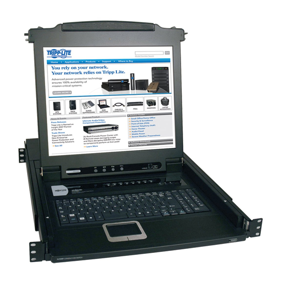
- Page 1 Console KVM Switch with IP Access B020-008-17-IP User Manual www.tripplite.com...
-
Page 2: Fcc Information
B020-008-17-IP User Manual FCC Information This is an FCC Class A product. In a domestic environment this product may cause radio interference in which case the user may be required to take adequate measures. This equipment has been tested and found to comply with the limits for a Class A digital device, pursuant to Part 15 of the FCC Rules. -
Page 3: User Information
Chapter 1. User Information User Notice All information, documentation, and specifications contained in this manual are subject to change without prior notification by the manufacturer. The manufacturer makes no representations or warranties, either expressed or implied, with respect to the contents hereof and specifically disclaims any warranties as to merchantability or fitness for any particular purpose. -
Page 4: Package Contents
Copyright © 2007 Tripp Lite. All rights reserved. All trademarks are the property of their respective owners. The policy of Tripp Lite is one of continuous improvement. Specifications are subject to change without notice. -
Page 5: Table Of Contents
Contents FCC Information ..........2 User Information . - Page 6 B020-008-17-IP User Manual Manual Port Switching ........39 Hot Plugging .
- Page 7 The OSD Toolbar ........91 Recalling the OSD.
- Page 8 B020-008-17-IP User Manual Help..........116 The Log Server Main Screen .
- Page 9 Chapter 1. Limited Warranty ......... . . 150...
-
Page 10: About This Manual
17-IP system. It covers all aspects of installation, configuration and operation. An overview of the information found in the manual is provided below. Overview Chapter 1, Introduction, introduces you to the B020-008-17-IP System. Its purpose, features and benefits are presented, and its front and back panel components are described. -
Page 11: Conventions
For information about all Tripp Lite products and how they can help you connect without limits, visit Tripp Lite on the Web or contact an Tripp Lite Authorized Reseller. Visit Tripp Lite on the Web for a list of locations and telephone numbers International –... - Page 12 B020-008-17-IP User Manual This Page Intentionally Left Blank...
-
Page 13: Chapter 1. Introduction
Chapter 1 Introduction Overview The B020-008-17-IP Console KVM Switch with IP Access is a control unit that allows secure access to multiple computers from a single KVM (keyboard, video, and mouse) console. A single B020-008-17-IP can control up to 8 computers. - Page 14 Remote operators can exchange keyboard, video and mouse signals with the computers attached to the B020-008-17-IP just as if they were present locally and working on the equipment directly. Enhanced features include a Panel Array Mode that displays the video output of up to 8 computers at the same time, and a Message Board that allows logged in users to conveniently and instantly communicate with one other –...
-
Page 15: Features
With its advanced security features, the B020-008-17-IP is the fastest, most reliable, most cost effective way to remotely access and manage widely distributed multiple computer installations. Features 8 port remote access KVM switch in a sliding dual rail housing with top and bottom clearance for smooth operation in a 1U high rack Integrated KVM console with 17"... - Page 16 B020-008-17-IP User Manual Three user account types: Administrator, User, and Select Advanced security features include password protection and advanced encryption technologies: 1024-bit RSA, 256-bit AES, 56-bit DES, and 128-bit SSL Supports RADIUS server authentication Supports CC1000 management Flash firmware upgradable over a network connection...
-
Page 17: Requirements
If you don't already have it, DirectX is available for free download from Microsoft's Website: http://www.microsoft.com/downloads. Users who want to access the B020-008-17-IP with the Java Client must have Sun's Java 2 (1.4.2 or higher) runtime environment installed. Java is available for free download from the Sun Java Website: http://java.sun.com. -
Page 18: Cables
Substandard cables may degrade system performance or damage your installation. For optimum signal integrity and reliability, we strongly recommend that you use Tripp Lite's high-quality, custom cable sets. To purchase cable sets contact your dealer. Lengths and part numbers are provided... -
Page 19: Operating Systems
Operating Systems Supported operating systems are shown in the table, below: Windows Linux RedHat SuSE Mandriva (Mandrake) UNIX FreeBSD Novell Netware OS/2 Chapter 1. Introduction Version 2000 and higher 6.0 and higher 8.2 and higher 9.0 and higher 4.3 and higher 3.51 and higher Solaris 8 and higher 5.0 and higher... -
Page 20: Components
B020-008-17-IP User Manual Components Front View Component Upper Handle Pull to slide the LCD module out; push to slide the module in. See Opening the Console, page 31, for details on sliding the console in and out. LCD Module See LCD Module, page 22. -
Page 21: Keyboard Module
Standard mouse touchpad Reset Switch Pressing and holding this switch in while powering on the unit causes the B020-008-17-IP to revert to the original factory installed firmware version – allowing you to recover from a failed firmware upgrade. Pressing and holding this switch in for more than three seconds performs a system reset. -
Page 22: Lcd Module
B020-008-17-IP User Manual (Continued from previous page.) Component Connection The LINK LED flashes when a remote client connects to LEDs the KVM switch. The 10/100 Mbps LED lights orange to indicate 10 Mbps data transmission speed. It lights green for 100 Mbps. -
Page 23: Rear View
KVM console. A custom console cable set is provided to attach the external console’s monitor, keyboard, and mouse. LAN Port The cable that connects the B020-008-17-IP to a LAN, WAN, or Internet plugs in here. KVM Ports The cables that link to the computers plug in here. - Page 24 B020-008-17-IP User Manual This Page Intentionally Left Blank...
-
Page 25: Chapter 2. Hardware Setup
Before You Begin 1. Important safety information regarding the placement of this device is provided on page 129. Please review it before proceeding. 2. Make sure that power to all the devices you will be connecting up has been turned off. You must unplug the power cords of any computers that have the Keyboard Power On function. -
Page 26: Standard Rack Mounting
B020-008-17-IP User Manual Standard Rack Mounting A standard rack mounting kit is provided with your B020-008-17-IP. The kit enables the switch to be mounted in a rack with a depth of 17”–30”. Note: It takes two people to mount the switch: one to hold it in place, the other to screw it in. - Page 27 2. While the first person still holds the switch in place, the second person slides the L brackets into the switch's side mounting brackets, from the rear until the bracket flanges contact the rack, then – using the screws provided with the rack mounting kit – screws the L brackets to the rack. 3.
-
Page 28: Single-Stage Installation
3. At the other end of the cable, plug the keyboard, video (blue), and mouse connectors into their respective ports on the computer. 4. Plug the cable from the LAN into the LAN port on the B020-008-17-IP’s rear panel. 5. Connect the power cord provided with this package to an AC source and the B020-008-17-IP’s power socket. - Page 29 Chapter 2. Hardware Setup Single-Stage Installation Diagram...
-
Page 30: Two Stage Installation
B020-008-17-IP’s KVM ports. As many as 64 computers can be controlled in a complete two stage installation. In a two stage installation, the B020-008-17-IP is considered the first stage unit; the cascaded switches are considered second stage units. -
Page 31: Chapter 3. Basic Operation
Opening the Console The B020-008-17-IP's console consists of two modules: an LCD display module located under the top cover; and a keyboard/touchpad module below the LCD module. The modules can either slide together, or independently. This allows you to have the LCD display available for viewing while the keyboard/touchpad module is conveniently out of the way when not in use. - Page 32 B020-008-17-IP User Manual (Continued from previous page.) 2. Pull the top panel all the way out until it clicks into place. 3. Rotate the top panel all the way back to expose the LCD screen.
-
Page 33: Opening Together
4. Reach underneath and pull the keyboard module all the way out until it clicks into place. Opening Together Refer to the diagrams in the Opening Separately section as you do the following: 1. Pull the release catches and pull the top and bottom panels out until the keyboard module clicks into place. -
Page 34: Operating Precautions
B020-008-17-IP User Manual Operating Precautions The maximum load bearing capacity of the keyboard module is 65lbs. Failure to heed the information below can result in damage to the keyboard module. RIGHT Rest your hands and arms lightly on the keyboard module as you work. -
Page 35: Closing The Console
Closing the Console 1. Pull the release catches located on either side of the keyboard toward you to release the keyboard module, then slide the module slightly in. 2. Let go of the catches. Using the front handle, push the keyboard module all the way in. - Page 36 B020-008-17-IP User Manual 3. Rotate the LCD module all the way down, then pull the rear catches to release the LCD module. 4. Using the front handle, push the module all the way in.
-
Page 37: Lcd Osd Configuration
LCD OSD Configuration The LCD Buttons The LCD OSD allows you to set up and configure the LCD display. Four buttons (see LCD Controls, page 22), are used to perform the configuration, as described in the table below: Button MENU EXIT Chapter 3. -
Page 38: The Adjustment Settings
B020-008-17-IP User Manual The Adjustment Settings An explanation of the LCD OSD adjustment settings is given in the table below: Setting Brightness Adjusts the background black level of the screen image. Contrast Adjusts the foreground white level of the screen image. -
Page 39: Port Selection
Powering Off and Restarting If it becomes necessary to power off the B020-008-17-IP, or if the switch loses power and needs to be restarted, wait 10 seconds before powering it back on. The computers should not be affected by this, but if any of them should fail, simply restart the affected computers. - Page 40 B020-008-17-IP User Manual This Page Intentionally Left Blank...
-
Page 41: Chapter 4. Administration
(grayed out) for users who do not have administration permission. The Local Console Once the B020-008-17-IP has been installed, the next step that the Administrator needs to perform is to set up the unit for user operation. The most convenient way to do this for the first time is from the local console. -
Page 42: The Main Page
B020-008-17-IP User Manual After you successfully log in, the Local Console OSD appears: The OSD consists of four pages, each with a specific set of functions: Main, Configuration, Administration, and Log. Each of page is discussed in the sections that follow. -
Page 43: Quick View Ports
Selecting certain ports as Quick View ports is a way of limiting which ports are included when the B020-008-17-IP is in Auto Scan mode. If the B020-008-17- IP is configured to only auto scan ports that have Quick View status (see Scan Select, page 50), designating a port as a Quick View port in this dialog box means that it will be included when auto scanning is in effect. -
Page 44: The List Function
B020-008-17-IP User Manual The List Function The List Function lets you broaden or narrow the scope of which ports the OSD displays (lists) in the Main Screen. To invoke the List Function, click the arrow at the upper right corner of the screen, or press [F3]:... - Page 45 The drop down list on the left offers four fixed choices as shown in the table, below: Choice Powered On Quick View Quick View + Powered On The text input box on the right allows you to key in a port name so that only port names that match what you key in show up in the list.
-
Page 46: Port Names
B020-008-17-IP User Manual Port Names To help remember which computer is attached to a particular port, every port can be given a name. This field allows the Administrator to create, modify, or delete port names. To configure a port name: 1. - Page 47 After a second or two, the bar changes to provide you with a text input box: 2. Key in the new Port Name, or modify/delete the old one. The maximum number of characters allowed for a Port Name is 19. You can use all letters, numbers, and symbols on the typewriter keys of keyboards with PC US English layout.
-
Page 48: Port Operation
B020-008-17-IP User Manual Port Operation Because the methods used to access the target device(s) are the same for the local console as for the Windows Client, the procedures are discussed in Windows Client Port Operation and Java Client Port Operation Chapters on pages 91 and 107, respectively. -
Page 49: The Configuration Page
The Configuration Page The OSD Configuration page allows users to set up their own, individual, working environments. The B020-008-17-IP stores a separate configuration record for each user profile, and sets up the working configuration according to the Username that is used to log in. - Page 50 Logout Timeout If there is no Operator input for the amount of time set with this function, the Operator is automatically logged out. A login is necessary before the B020-008-17-IP can be accessed again. Enter a value from 0 - 180 minutes. The default is 30 minutes. 0 disables the function.
-
Page 51: The Administration Page
MAC Address This item displays the B020-008-17-IP's MAC address. Firmware Ver This item displays the current firmware version number. You can reference it to see if there are newer versions available on the Tripp Lite Website. -
Page 52: User Management
B020-008-17-IP User Manual User Management The User Management dialog box is used to create and manage user profiles. Up to 64 user profiles can be established. To delete a user profile, select it in the list box, and Click Remove. - Page 53 2. Checking Windows Client allows a user to access the B020- 008-17-IP via the Windows Client software. By default, all users may access the B020-008-17-IP via the Windows Cli- ent software. 3. Checking Log allows a User to view and query the log file.
- Page 54 B020-008-17-IP User Manual (Continued from previous page.) Heading Port Access This function allows the Administrator or a User with Administration permission to define the selected User's access to the computers on a Port-by-Port basis. For each User profile, select a port and click it to cycle...
-
Page 55: Service Configuration
As a security measure, if a firewall is being used, the Administrator can specify the port numbers that the firewall will allow, and set the firewall accordingly. Users must specify the port number when they log in to the B020-008-17-IP. If an invalid port number (or no port number) is specified, the B020-008-17-IP will not be found. -
Page 56: Network
The Network dialog is used to specify the B020-008-17-IP's network environment. Network Transfer Rate Set the rate at which the B020-008-17-IP transfers data to remote computers. The range is from 8 to 99999 Kilobytes per second (KBps). IP Address The B020-008-17-IP can either have its IP address assigned dynamically (DHCP), or it can be given a fixed IP address. - Page 57 Chapter 4. Administration DNS Server For automatic DNS Server address assignment, select the Obtain DNS Server address automatically, radio button. To specify the DNS Server address manually, select the Use the following DNS Server radio button, and fill in the addresses for the Primary and Alternate DNS servers.
-
Page 58: Anms
2. Fill in the IP addresses and Service Ports for the Primary and Alternate RADIUS servers. 3. Set the time in seconds that the B020-008-17-IP waits for a RADIUS server reply before it times out in the Timeout field. 4. Set the number of RADIUS retries allowed in the Retries field. -
Page 59: Radius Server Access Rights Table
RADIUS Server Access Rights Table: Character Grants the user administrator privileges, allowing the user to configure the system. Allows the user to access the system via the Windows Client program. Allows the user to access the system via the Java Client program. Allows the user to access log information via the user’s browser. - Page 60 CC Management Settings To allow authorization for the B020-008-17-IP through a CC (Control Center) server, check Enable CC Management and fill in the CC Server’s IP address and the port that it listens on in the appropriate fields.
-
Page 61: Security
If any filters have been configured, they appear in the IP Filter and/or MAC Filter list boxes. IP and MAC Filters control access to the B020-008-17-IP based on the IP and/or MAC addresses of the computers attempting to connect. A maximum of 100 IP filters and 100 MAC filters are allowed. - Page 62 The Default web page name entry field lets the Administrator specify a login string (in addition to the IP address) that the user must include when accessing the B020-008-17-IP with a browser. For example: 192.168.0.126/abcdefg The user must include the forward slash and the string along with the IP address.
-
Page 63: Customization
Customization The Customization dialog box is arranged in four major sections: Login Failures; Working Mode; I/O; and untitled miscellaneous functions at the bottom. The functions of each of the Customization items are described in the sections that follow: Login Failures Allowed: sets the number of consecutive failed login attempts that are permitted from a remote computer. - Page 64 Working Mode If Stealth Mode is enabled, the B020-008-17-IP cannot be pinged. To permit browser access to the B020-008-17-IP, click to put a check mark in the Enable Browser checkbox. If browser access is not enabled, users will not be able to log into the unit via their browsers.
- Page 65 (Continued from previous page.) To set a port’s Share mode, double click it to bring up the I/O attributes dialog box: Set the port’s Share mode according to the information in the following table:: Attribute Exclusive: The first user to occupy the port has exclusive control over it. No other user can view or access it.
- Page 66 Parameter Reset on exit Place a check here to have the B020-008-17-IP reset itself and implement all the new settings when you log out. Following the reset, wait one to two minutes before logging back in.
-
Page 67: Date/Time
If your country or region employs Daylight Saving Time (Summer Time), check the corresponding box. To establish the time zone that the B020-008-17-IP is located in, drop down the Time Zone list and choose the city that most closely corresponds to where it is at. -
Page 68: The Log Page
B020-008-17-IP User Manual The Log Page Clicking the Log tab brings up the contents of the log file. The log file is discussed in Chapter 8. -
Page 69: Upgrading The Firmware
1. Download the new firmware file to a computer that is not part of your B020-008-17-IP installation. 2. From that computer, open your browser and log in to the B020-008-17-IP (see Logging In, page 71). 3. Click the Firmware icon (see Webpage Icons, page 73) to open the Firmware configuration dialog box: 4. - Page 70 B020-008-17-IP User Manual This Page Intentionally Left Blank...
-
Page 71: Chapter 5. Browser Operation
To log in from an Internet browser: 1. Open the browser and specify the IP address and Default Webpage name (if one has been specified) for the B020-008-17-IP in the URL bar. Note: If you don't know the IP address and Default Webpage name, get it from the B020-008-17-IP administrator. - Page 72 B020-008-17-IP User Manual 3. Provide a valid Username and Password (set up by the B020-008-17-IP administrator), then Click Login to continue. Note: 1. If you supply an invalid login, the authentication routine will return a message stating, Invalid Username or Password. Please try again.
-
Page 73: Webpage Layout
Click this icon to display the General dialog box. See The General Dialog Box, page 74, for an explanation of the dialog box fields. Click this icon to synchronize the B020-008-17-IP's time with your computer's time. If both are in the same time zone, the device's time is changed to match the computer's time. -
Page 74: The General Dialog Box
Last IP from DHCP Displays the current IP address of the B020-008-17-IP. server Note: New versions of the B020-008-17-IP's firmware can be downloaded from our Website as they become available. See page 69 for details. Purpose... -
Page 75: Webpage Buttons
Clicking this button allows the administrator to download and install the Log Server application. See Chapter 9 for Log Server details. All the events that take place on the B020-008-17-IP are recorded in a log file. Clicking this icon displays the contents of the log file. - Page 76 B020-008-17-IP User Manual This Page Intentionally Left Blank...
-
Page 77: Windows Client Port Operation
3. If a second security warning dialog box appears, click Run again. Note: 1. If the browser cannot run the file, save it to disk, instead. Then, with your browser still open to the B020-008-17-IP Webpage, run the file from your disk. - Page 78 B020-008-17-IP User Manual (Continued from previous page.) 4. When a connection to the B020-008-17-IP has been established a screen similar to the one below appears: 5. Click on Connect and the B020-008-17-IP Window Client login screen appears: 6. Provide a valid Username and Password (set up by the B020-008-17-IP administrator), then Click Login to continue.
- Page 79 7. After you have successfully logged in, the Windows Client Main screen reappears with the Message List indicating the server is ready and the Switch to Remote View and Change Password buttons activated: 8. Click on Switch to remote View to bring up the OSD. Chapter 6.
-
Page 80: The Windows Client Osd
B020-008-17-IP User Manual The Windows Client OSD After you switch to the B020-008-17-IP the OSD comes up with the Main page and Windows Client Control Panel displayed: The OSD consists of three pages – Main, Configuration, and Administration. The Configuration and Administration pages are discussed in Chapter 4. -
Page 81: Windows Client Control Panel
Windows Client Control Panel The control panel consists of an icon bar at the top, with two text bars below it. Initially, the text bars display the video resolution and IP address of the device at the remote location. As the mouse pointer moves over the icons in the icon bar, however, the text bar information changes to describe the icon's function. -
Page 82: Hotkey Setup
B020-008-17-IP User Manual Hotkey Setup Various configuration actions related to the keyboard, video, and mouse can be performed via hotkey combinations. The Hotkey setup utility is accessed by clicking the Keyboard icon on the Control Panel. The actions performed by the Hotkeys are listed in the left panel;... - Page 83 Substitute Alt key Although all other keyboard input is captured and sent to the B020-008-17-IP, [Alt + Tab] and [Ctrl + Alt + Del] work on your local computer. In order to implement their effects on the remote system, another key may be substituted for the Alt key.
-
Page 84: Video Adjustment
B020-008-17-IP User Manual Video Adjustment You can adjust the placement and the picture quality of the remote screen (as displayed on your local monitor) with the Video Options function. To do so, either click on the Hammer icon on the Control Panel, or use the Adjust Video hotkeys (see Hotkey Setup, page 82). - Page 85 Enable Refresh The B020-008-17-IP can redraw the screen every 1 to 99 seconds, eliminating unwanted artifacts from the screen. Select Enable Refresh and enter a number from 1 through 99. The B020-008-17-IP will redraw the screen at the interval you specify.
- Page 86 B020-008-17-IP User Manual Gamma Adjustment If it is necessary to correct the gamma level for the remote video display, use the Gamma function of the Video Adjustment dialog box. Under Basic configuration, there are ten preset and four user-defined levels to choose from. Drop down the list box and choose the most suitable one.
-
Page 87: The Message Board
Chapter 6. Windows Client Port Operation The Message Board The B020-008-17-IP supports multiple user logins, which can possibly give rise to access conflicts. To alleviate this problem, a message board feature has been provided, allowing users to communicate with each other. -
Page 88: The Button Bar
B020-008-17-IP User Manual The Button Bar The buttons on the Button Bar are toggles. Their actions are described in the table below: Button Enable/Disable Chat. When disabled, messages posted to the board are not displayed. The button is shadowed when Chat is disabled. The icon displays next to the user's name in the User List panel when the user has disabled Chat. - Page 89 User List Panel The names of all the logged in users are listed in this panel. Your name appears in blue; other users' names appear in black. By default, messages are posted to all users. To post a message to one individual user, select the user's name before sending your message.
-
Page 90: The Main Page
B020-008-17-IP User Manual The Main Page The Main Page (see page 80), lists all of the B020-008-17-IP's ports and governs port access. Selecting a port and double clicking it switches you to the device on that port. Note: The administrator selects which ports are accessible to each user with the User Management function (see page 52 for details). -
Page 91: Port Operation
The OSD Toolbar The OSD provides a toolbar to help you control the B020-008-17-IP from within the captured port. To bring up the toolbar, tap the OSD Hotkey (Scroll Lock or Ctrl) twice. The toolbar appears in the upper left corner of the screen: Depending on the settings that were selected under ID Display (see page 50), the Port Number and/or the Port Name display at the right of the toolbar. -
Page 92: Osd Hotkey Summary Table
Click to skip to the first accessible port previous to the current one without having to invoke the OSD. Click to begin Auto Scan Mode. The B020-008-17-IP automatically switches among the ports that were selected for Auto Scanning under the Configuration Scan Select function (see page 50). -
Page 93: Multiuser Operation
Multiuser Operation The B020-008-17-IP supports multiuser operation. Up to 32 users can log in at the same time. When multiple users simultaneously access the B020-008-17- IP switch from remote computers, the rules of precedence that apply are shown in the following table:... -
Page 94: Keyboard Hotkey Operation
B020-008-17-IP User Manual Keyboard Hotkey Operation Keyboard hotkey combinations allow you to provide KVM focus to a port directly from the keyboard. The B020-008-17-IP provides the following hotkey features: Auto Scanning Skip Mode Switching The hotkeys are: A and P for Auto Scanning; and the Arrow Keys for Skip Mode. -
Page 95: Pausing Auto Scan
Pausing Auto Scan While you are in Auto Scan Mode, you can pause the scanning in order to keep the focus on a particular computer by pressing P. During the time that Auto Scanning is paused, the S in front of the Port ID blinks On and Off. Pausing when you want to keep the focus on a particular computer is more convenient than Exiting Auto Scan Mode because when you Resume scanning, you start from where you left off. -
Page 96: Keyboard And Mouse Considerations
Note: 1. While any key may be used as a Substitute key, you must not use one that is being used as the first position Hotkey for another action. 2. When the B020-008-17-IP is being accessed with Win 98 under Full Screen Mode, if you mistakenly press Ctrl + Alt + Del, you will have... -
Page 97: Mouse Synchronization
Mouse Synchronization Until you close the B020-008-17-IP connection, mouse movements have no effect on your local system, but instead are captured and sent to the remote system. From time to time, especially if you change video resolution, the local mouse movement may no longer be synchronized with the remote system's mouse pointer. - Page 98 B020-008-17-IP User Manual This Page Intentionally Left Blank...
-
Page 99: Java Client Port Operation
Open. Note: 1. If the browser cannot run the file, save it to the hard drive. Then, with your browser still open to the B020-008-17-IP Webpage, run the file from your disk. 2. If you use the save to disk method, for security purposes, you cannot simply run a previously downloaded version of the program. -
Page 100: The Java Client Osd
B020-008-17-IP User Manual The Java Client OSD When you bring up the OSD, the Main Screen comes up in the center of your monitor. The OSD consists of three pages – Main, Configuration, and Administration. The Configuration and Administration pages are discussed in Chapter 4. -
Page 101: The Java Client Control Panel
The Java Client Control Panel Instead of a control panel like the one that the Windows Client uses, the Java Client has a hidden control panel, located at the bottom center of the screen. The panel becomes visible when the mouse pointer is moved over it. The Java Client Control Panel icons and their functions are described in the sections that follow. -
Page 102: Keypad
B020-008-17-IP User Manual Keypad Some keyboard combinations cannot be captured and sent to the B020-008-17-IP. In order to implement their effects on the remote system, this function provides a one-click implementation of some common window control combinations. Mouse Synchronization At times the local mouse movement may lose sync with the remote mouse movement. -
Page 103: Message Board
Message Board The B020-008-17-IP supports multiple user logins, which can possibly give rise to access conflicts. To alleviate this problem, a message board feature, similar to an Internet chat program, allows users to communicate with each other. When you click the Message Board icon on the Java Client Control Panel (see page 101), a screen similar to the one below appears: Chapter 7. -
Page 104: The Message Board Button Bar
B020-008-17-IP User Manual (Continued from previous page.) The Message Board Button Bar The buttons on the Button Bar are toggles. Their actions are described in the table below: Button Enable/Disable Chat. When disabled, messages posted to the board are not displayed. The button is shadowed when Chat is disabled. - Page 105 (Continued from previous page.) Messages that users post to the board - as well as system messages - display in the Message Display panel. If you disable Chat, however, messages that get posted to the board won't appear. Key in the messages that you want to post to the board in the Compose panel.
-
Page 106: Lock Key Leds And Resolution
B020-008-17-IP User Manual Lock Key LEDs and Resolution These LEDs show the Num Lock, Caps Lock, and Scroll Lock status of the remote computer. They turn Green when the Lock status is On. Click on the icon to toggle the status. -
Page 107: Port Operation
Chapter 7. Java Client Port Operation Port Operation Java Client port operation is the same as for the Windows Client. See Port Operation, page 91, for details. Keyboard Hotkey Operation Keyboard hotkey operation is the same as for the Windows Client. See Keyboard Hotkey Operation, page 94, for details. - Page 108 B020-008-17-IP User Manual This Page Intentionally Left Blank...
-
Page 109: Chapter 8 The Log File
The Main Screen The B020-008-17-IP logs all the events that take place on it. To view the contents of the log file, click the Log icon at the left of the Webpage. A screen similar to the one below appears: A maximum of 512 events are stored in the log file. - Page 110 B020-008-17-IP User Manual This Page Intentionally Left Blank...
-
Page 111: Chapter 9. The Log Server
The Windows-based Log Server is an administrative utility that records all the events that take place on selected B020-008-17-IP units and writes them to a searchable database. This chapter describes how to install and configure the Log Server. Installation 1. From the computer that you want to use as the Log Server, open your browser and log into the B020-008-17-IP (see page 71). -
Page 112: Starting Up
The screen is divided into three components: A Menu Bar at the top A panel that will contain a list of B020-008-17-IP units in the middle (see The Log Server Main Screen, page 117, for details). A panel that will contain an Events List at the bottom... -
Page 113: The Menu Bar
Options Help These are discussed in the sections that follow. Note: If the Menu Bar appears to be disabled, click in the B020-008-17-IP List window to enable it. Configure The Configure menu contains three items: Add, Edit, and Delete. They are used... -
Page 114: Events
A description of the fields is given in the table, below: Field Address This can either be the IP address of the B020-008-17-IP or its DNS name (if the network administrator has assigned it a DNS name). Port The port number that was assigned to the Log Server in the B020-008- 17-IP OSD (see Log Server, page 56). - Page 115 Server List B020-008-17-IP units are listed according to their IP address. Select the unit that you want to perform the search on from this list. You can select more than one unit for the search. If no units are selected, the search is performed on all of them.
-
Page 116: Options
B020-008-17-IP User Manual Options Network Retry allows you to set the number of seconds that the Log Server should wait before attempting to connect if the previous attempt to connect failed. When you click this item, a dialog box, similar to the one below appears: Key in the number of seconds, then click OK to finish. -
Page 117: The Log Server Main Screen
Log Server to track (see Configure, page 113). The lower (Event) panel displays the log events for the currently selected B020-008-17-IP (the highlighted one - if there are more than one). To select a B020-008-17-IP unit in the list, simply click on it. -
Page 118: The List Panel
Recording Determines whether the Log Server records log events for this B020-008-17-IP or not. If the Recording check box is checked, the field displays Recording, and log events are recorded. If the Recording check box is not checked, the field displays Paused, and log events are not recorded. -
Page 119: Chapter 10. Ap Operation
Overview In some cases, the Administrator may not want the B020-008-17-IP to be available via browser access. AP versions of the Windows Client and the Java Client are provided to enable direct access of the B020-008-17-IP without having to go through a browser. -
Page 120: Starting Up
B020-008-17-IP User Manual Starting Up To connect to the B020-008-17-IP, go to the location on your hard disk that you saved the Windows Client program to, and double-click its icon (WinClient.exe) to bring up the Windows Client Connection Screen: Note: You must have DirectX 7.0 or higher installed on your computer. If not, the Client program will not load. - Page 121 Lists status messages regarding the connection to the B020- 008-17-IP. Switch to Remote View Once contact with a B020-008-17-IP has been established, this button becomes active. Click it to switch and take over console control of the unit that is attached to the B020-008- 17-IP.
-
Page 122: The File Menu
B020-008-17-IP User Manual The File Menu The File Menu allows the operator to Create, Save, and Open user created Work files. A Work File consists of all the information specified in a Client session. This includes the Server List and Server IP list items, as well as the Hotkey settings. - Page 123 Config When you select Config, a screen similar to the one below appears: If Full Screen Mode is enabled (there is a checkmark in the box), the remote display fills the entire screen of your local monitor. If Full Screen Mode is not enabled (there is no checkmark in the box), the remote display appears as a window on your desktop.
-
Page 124: Connecting
While it does so, you can check the Message List window for status messages regarding the operation's progress. 3. Once contact with the B020-008-17-IP has been established, the Switch to Remote View button becomes active. Click it to connect to the B020-008-... -
Page 125: Operation
The look and feel of the AP Windows client operation is the same as for the browser version of the Windows client. Refer back to page 77 for details. Ending the Session After you log out of the B020-008-17-IP, you return to the Connection dialog box. Click Disconnect to end the session. -
Page 126: The Java Client
Installation To install the Java Client on your computer, do the following: 1. Log into the B020-008-17-IP with your browser, and click the second Java Client button (the one with the arrow). A screen similar to the one below appears: 2. - Page 127 (Continued from previous page.) The Address Input dialog box appears: 3. Key in the IP address for the unit you want to connect to - including a forward slash followed by the login string. Note: For security purposes, the login string (set by the administrator), must be specified correctly as part of the IP address.
-
Page 128: Operation
B020-008-17-IP User Manual Operation The look and feel of the AP Java client operation is the same as for the browser version of the Java client. Refer back to Chapter 7, Java Client Port Operation for details. -
Page 129: Appendix
Safety Instructions General Read all of these instructions. Save them for future reference. Follow all warnings and instructions marked on the device. Do not place the device on any unstable surface (cart, stand, table, etc.). If the device falls, serious damage will result. Do not use the device near water. - Page 130 B020-008-17-IP User Manual To help protect your system from sudden, transient increases and decreases in electrical power, use a Tripp Lite surge suppressor, line conditioner, or uninterruptible power supply (UPS). Position system cables and power cables carefully; Be sure that nothing rests on any cables.
-
Page 131: Rack Mounting
Appendix Rack Mounting Before working on the rack, make sure that the stabilizers are secured to the rack, extended to the floor, and that the full weight of the rack rests on the floor. Install front and side stabilizers on a single rack or front stabilizers for joined multiple racks before working on the rack. -
Page 132: Specifications
B020-008-17-IP User Manual Specifications Function Computer Direct Connections Max. Console Local Connections Remote Port Selection Connectors Console Keyboard 1 x 6-pin Mini-DIN Female (Purple) Port Video Mouse KVM Port Power External Mouse Switches Reset Power Port Selection LCD Power LCM Adjustment... -
Page 133: Osd Factory Default Settings
Port ID Display Duration Scan / Skip Mode Scan Duration Screen Blanker Beeper Accessible Ports B020-008-17-IP PS/2 1280 x 1024 @ 75 Hz; DDC2B 1600 x 1200 @ 60 Hz; DDC2B 1–255 Seconds 100–240V AC, 50/60 Hz, 1A 120V/31W; 230V/39W 0–50°... -
Page 134: Trusted Certificates
B020-008-17-IP User Manual Trusted Certificates Overview When you try to login to the B020-008-17-IP from your Web browser, a Security Alert message appears to inform you that the device’s certificate is not trusted, and asks if you want to proceed. -
Page 135: Installing The Certificate
Installing the Certificate To install the certificate: 1. In the Security Alert dialog box, click View Certificate. The Certificate dialog box appears. Note: There is a red and white X logo over the certificate to indicate that it is not trusted. 2. -
Page 136: Certificate Trusted
B020-008-17-IP User Manual 5. Click Finish to complete the installation. 6. Click OK to close the dialog box. Certificate Trusted The certificate is now trusted: When you click View Certificate, you can see that the red and white X logo is... -
Page 137: Troubleshooting
B020- displaying cached 008-17-IP still Webpages and has not appears to be using fetched new versions of the old firmware the B020-008-17-IP version. Webpages. After making changes You are using Windows and checking Reset 2000 Professional and IE 5... -
Page 138: General Operation
B020-008-17-IP User Manual General Operation Problem Erratic operation Mouse and/or keyboard not responding Sudden loss of network connection When logging in from a browser, the following message appears: 404 Object Not Found. Two pointers appear when I login from a remote computer. - Page 139 1280 x 1024. Note: Although the LCD monitor only supports video resolutions of up to 1280 x 1024, the B020-008-17-IP, itself can support video resolutions up to 1600 x 1200 @ 60 Hz. If you wish to set the screen resolutions of the...
-
Page 140: The Java Client
2. Make sure to include the forward slash and login string (see Default Webpage Name, page 62) when you specify the B020-008-17-IP's IP address. 3. Close the Java Client, reopen it, and try again. Java doesn't support the Windows Menu key. -
Page 141: Panel Array Mode
The Windows Client Problem The Windows Client won't connect to the B020-008-17-IP. The remote computer’s pointer is out of sync. Part of the remote window is off my monitor. -
Page 142: Sun Systems
B020-008-17-IP User Manual Sun Systems Problem Video display problems with HDB-15 interface systems (e.g. Sun Blade 1000 servers). Video display problems with 13W3 interface systems (e.g. Sun Ultra servers).* * These solutions work for most common Sun VGA cards. If using them fails to resolve the problem, consult the Sun VGA card's manual. -
Page 143: Screen Resolutions Higher Than 1280 X 1024
1600 x 1200 @ 60 Hz to the B020-008-17-IP’s external console ports. 1. From a remote computer, log into the B020-008-17-IP and access the computer whose screen resolution you wish to change. 2. Open the computer’s Control Panel and double-click Display. The Display Properties dialog box appears. - Page 144 B020-008-17-IP User Manual 10. If the Monitor Settings dialog box appears requesting you to confirm the settings change, click Yes. 11. After the Monitor Settings dialog box closes, click OK. 12. In the Display Properties dialog box, click OK. This completes the procedure. Repeat these steps for any other computer whose...
-
Page 145: Additional Mouse Synchronization Procedures
Note: 1. These procedures are to be performed on the computers attached to the B020-008-17-IP's ports - not on the computer you are using to access the B020-008-17-IP. 2. In order for the local and remote mice to synchronize, you must use the generic mouse driver supplied with the Windows operating system. - Page 146 B020-008-17-IP User Manual Windows XP / Windows Server 2003: Set the mouse speed to the middle position; disable Enhance Pointer Precision (Control Panel → Printers and Other Hardware → Mouse → Pointer Options): Windows ME / Windows 95: Set the mouse speed to the middle position; disable mouse acceleration (click Advanced to get the dialog box for this).
-
Page 147: Administrator Login Failure
Note: Performing this procedure also returns all settings to their defaults. To clear the login information (and return all settings to their defaults), do the following: 1. Power off the B020-008-17-IP and remove the power cord from the power socket. 2. Remove the cover from the B020-008-17-IP. -
Page 148: Dedicated Invocation Keys
The KVM OSD Key invokes the OSD See The Local Console, page 41, for details. The KVM Hotkey Key opens the OSD Toolbar, which allows you to control the B020-008-17-IP from within the captured port. See The OSD Toolbar, page 91, for details. -
Page 149: About Sphd Connectors
The following is a list of supported KVM switches that can be cascaded from the B020-008-17-IP. B007-008 Note: The B020-008-17-IP OSD port list does not display ports on cascaded KVM switches. After accessing a cascaded switch, invoke its OSD to manage its ports. -
Page 150: Limited Warranty
B020-008-17-IP User Manual Limited Warranty TRIPP LITE warrants its products to be free from defects in materials and workmanship for a period of one (1) year from the date of initial purchase. TRIPP LITE’s obligation under this warranty is limited to repairing or replacing (at its sole option) any such defective products. To obtain service under this warranty, you must obtain a Returned Material Authorization (RMA) number from TRIPP LITE or an authorized TRIPP LITE service center. - Page 151 Windows Client, 119 Auto Scanning, 94 Invoking Auto Scan, 94 Multiuser Operation, 93 Pausing Auto Scan, 95 Scan Duration, 50 Setting the Scan Interval, 94 B020-008-17-IP Front View, 20 Rear View, 23 Basic Operation, 31 Beeper, 50 Browser General Dialog Box, 74...
- Page 152 B020-008-17-IP User Manual keyboard, 94, 107 Hotkey setup, 82 Hotkeys Windows Client, 82, 122 Installation Cascading, 30 Single Stage, 28 Invalid login, 72, 78 IP Address, 74 Configuring, 56 Java Client, 14, 126 Activating the OSD, 99 AP Installation, 126...
- Page 153 Opening the Console, 31 Operating Precautions, 34 Operation AP, 119 Activating in Windows, 77 Administration Page, 51 Configuration Page, 49 Factory Default Settings, 133 Hotkey, 50 Java, 99 Java client, 100 Log Page, 68 Main Page, 42, 90 Toolbar, 91 Windows client, 80 Overview, 13 Panel Array Mode...
- Page 154 B020-008-17-IP User Manual OSD, 91 Troubleshooting Administration, 137 General operation, 138 Java Client, 140 Log Server, 140 Login Failure, 147 Panel Array Mode, 141 Sun Systems, 142 Windows Client, 141 Trusted Certificates, 134 Upgrading the Firmware, 69 User Management, 52...
- Page 155 Port Selection ..........39 B020-008-17-IP User Manual...
- Page 156 B020-008-17-IP User Manual Manual Port Switching ........39 Hot Plugging .
- Page 157 Options ..........116 B020-008-17-IP User Manual...
- Page 158 B020-008-17-IP User Manual Help..........116 The Log Server Main Screen .
- Page 159 B020-008-17-IP User Manual Limited Warranty ......... . . 150...
- Page 160 B020-008-17-IP User Manual...