Table of Contents
Advertisement
Quick Links
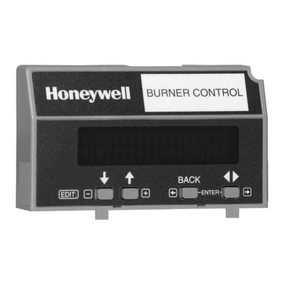
7800 SERIES S7800A1167
Keyboard Display Module
APPLICATION
The S7800A1167 Keyboard Display Module (KDM) provides
current system status along with first-out annunciation and
system diagnosis using a two-row by twenty-column readout.
The KDM provides local or remote annunciation of operation
and fault information, remote reset, report generation, burner
control data and diagnostic information. The KDM is part of
the 7800 SERIES of microprocessor-based burner controls for
gas, oil, coal or combination fuel single burner applications.
The 7800 SERIES is programmed to provide a level of safety,
functional capabilities and features beyond the capacity of
conventional controls.
The S7800A1167 is required to program the Valve Proving
feature of select 7800 Series devices.
Application ........................................................................
Features ...........................................................................
Specifications ...................................................................
Ordering Information ........................................................
Air cleaner Installation ......................................................
Wiring ...............................................................................
Troubleshooting ................................................................ 12
Hold and Fault Message Summary .................................. 16
Appendix A: Display Setup ............................................... 25
Display Setup-CLONE ............................... 25
The S7800A1167 KDM offers the following technical
advancements to the 7800 SERIES devices:
• Compatible with installed Honeywell 7800 SERIES
systems.
• When used with the new 7800 SERIES with Valve Proving
Feature, the KDM allows for programming the Valve
Proving Control feature and timing (Pass Code protected
feature).
• Allows for naming the S7830 Expanded Annunciator
terminals to match your system drawings. (Displayed
message only.)(Pass Code protected feature.)
• A three screen two-row by twenty-column readout set of
"Call Service" (Business Card) alpha/numeric directions
can be displayed instead of the standard lockout display
message. (Pass Code protected feature). This "business
card" can be cloned to other displays to save setup time.
• Enable ModBus Communication feature.
The Business Card (Call Service) and Expanded Annunciator
can be made up using:
• Capital letters (A through Z).
• Lower case letters (a through z).
• Numbers (1 through 0).
• Symbols (!, @, #, $,%, etc.).
• Spanish symbols.
Programming can be done with the S7800 KDM mounted on a
7800 SERIES Relay Module or with a 13 Vdc power source
connected to the KDM through the 203541 5-wire connector.
Since your Business Card (Call Service) S7800A1167 will be
left at the job site, programming your personal three-number
password and personal lockout message can be set up ahead
of time without being connected to a 7800 SERIES device. A
clone function allows you to make multiple Business Cards
from the original display.
1
Appendix A: Display Setup-Clear All .............................. 27
2
Display Setup-CEA Assign ......................... 29
2
Display Setup-CS ON/OFF ........................ 30
2
Display Setup-CS EDIT .............................. 32
3
Appendix B: Valve Proving System ................................... 33
4
Setup of Valve Proving Function .................. 34
Appendix C: Setup of Post Purge ..................................... 35
Appendix D: Expanded Annunciator Tables ..................... 37
Appendix E: ModBus Function ......................................... 38
PRODUCT DATA
Contents
65-0311-02
Advertisement
Chapters
Table of Contents

Related Manuals for Honeywell S7800A1167


Summary of Contents for Honeywell S7800A1167
-
Page 1: Table Of Contents
KDM through the 203541 5-wire connector. the 7800 SERIES of microprocessor-based burner controls for Since your Business Card (Call Service) S7800A1167 will be gas, oil, coal or combination fuel single burner applications. left at the job site, programming your personal three-number... -
Page 2: Features
If you have additional questions, need further information, or would like to comment on our products or services, please write or phone: 1. Your local Honeywell Automation and Control Products Sales Office (check white pages of your phone directory). 2. Honeywell Customer Care... -
Page 3: Air Cleaner Installation
1. Read these instructions carefully. Failure to follow them ule for the ModBus option. could damage the product or cause a hazardous condi- B. The S7800A1167 KDM is also used to program the Valve tion. Proving and Post-purge feature of Select RM7800 SERIES 2. -
Page 4: Wiring
7800 SERIES S7800A1167 KEYBOARD DISPLAY MODULE Mounting KDM on 7800 SERIES Relay 3. Use the KDM or Data ControlBus Module™ as a template (Fig. 19) and mark the two screw locations, interlocking Module. ear locations and the two plug-in connector locations. - Page 5 7800 SERIES S7800A1167 KEYBOARD DISPLAY MODULE 1. Refer to Fig. 5, 6, and 7 for proper wiring. 5. For KDM: The KDM is powered from a low voltage, 2. Make sure all wiring complies with all applicable energy-limited source. It can be mounted outside of a electrical codes, ordinances and regulations.
- Page 6 7800 SERIES S7800A1167 KEYBOARD DISPLAY MODULE Annunciator). When the arrow and two-letter code are displayed, it indicates the second line is showing a selectable S7800 KEYBOARD DISPLAY MODULE message submenu. The second line will display selectable or (MOUNTED ON 7800 SERIES RELAY MODULE) preemptive messages.
- Page 7 7800 SERIES S7800A1167 KEYBOARD DISPLAY MODULE MOMENTARY PC/PLC PUSHBUTTON RS-485 SWITCH RM78xx SERIES DEVICE WITH S7800 SERIES 5 OR GREATER DISPLAY. MOMENTARY PUSHBUTTON SWITCH RM78xx SERIES DEVICE WITH S7800 SERIES 5 OR GREATER DISPLAY. MULTI-DROP RS-485 COMMUNICATION BUS. UP TO 31 S7800 SERIES 5 OR GREATER DISPLAYS CAN BE CONNECTED TO A SINGLE BUS WITHOUT AN RS-485 REPEATER.
- Page 8 7800 SERIES S7800A1167 KEYBOARD DISPLAY MODULE 1. Down-up arrow push-buttons. See Fig. 10. The down-up arrow push-buttons are used to scroll through the selectable messages. The double-headed arrow ( ), which is located in the lower left position of the second line of the display, represents the down-up push-buttons.
- Page 9 7800 SERIES S7800A1167 KEYBOARD DISPLAY MODULE M22873 Fig. 12. BACK push-button function. 4. SAVE function, see Fig. 13, 14, and 15. a. Enables users to identify the selectable 2nd line message they want to view upon power restoration. (See “Total Cycles” instead of “Flame Signal” for example.) The second line selectable message is...
-
Page 10: Opercontrol
7800 SERIES S7800A1167 KEYBOARD DISPLAY MODULE Table 3. Selectable Messages (Continued). Selectable Possible States/ Range Message/Display Description (Terminals) Comments Number that identifies the 0 - 999 — Fault Code reason for lockout. Indicates cause of lockout. — — *Fault Message* Indicates where in the —... - Page 11 7800 SERIES S7800A1167 KEYBOARD DISPLAY MODULE Table 3. Selectable Messages (Continued). Selectable Possible States/ Range Message/Display Description (Terminals) Comments Pilot Valve. INTACT/CLIPPED Display shows state of Pilot Jumper 2 Valve (terminal no. 21). If jumper is intact, RM7800G has Intermittent Pilot Valve. If...
-
Page 12: Troubleshooting
7800 SERIES S7800A1167 KEYBOARD DISPLAY MODULE Table 4. Expanded Annunciator. Selectable Message (Second Line) Display Value (Second Line) First Line Message Low water Cutoff (LWCO) T9 = 1 or 0< High Limit (High Limit) T10 = 1 or 0< Auxiliary Limit (AuxLimit 3) T11 = 1 or 0<... - Page 13 7800 SERIES S7800A1167 KEYBOARD DISPLAY MODULE Table 5. Keyboard Display Module Sequence and Status Hold Messages . Sequence Status INITIATE mm:ss The Keyboard Display Module (KDM) indicates the burner status, INITIATE, a stabilization period for the relay module to check for any fluctuations in ac line voltage inputs or control inputs on power up or during normal operation.
- Page 14 7800 SERIES S7800A1167 KEYBOARD DISPLAY MODULE Table 5. Keyboard Display Module Sequence and Status Hold Messages (Continued). Sequence Status PURGE HOLD: T18 The KDM indicates the burner status and that the Low Fire Switch is not closed. The firing rate motor is (Low Fire Switch) driving to its Low Fire position in preparation for Ignition Trials.
- Page 15 7800 SERIES S7800A1167 KEYBOARD DISPLAY MODULE Table 6. Accessing Historical and Diagnostic Selectable Messages. Step Operation Press Display Comments Press keys to access Diagnostic STANDBY Use the Down/Up SCROLL keys to access the Information. Diagnostic Info> selectable message. The second line will display Diagnostic Information.
-
Page 16: Hold And Fault Message Summary
7800 SERIES S7800A1167 KEYBOARD DISPLAY MODULE 4. State 4: In the fourth state, both lines are blanked for NOTE: For further explanation of Lockout Messages, one-half second, then the display sequences to the first Troubleshooting and Checkout, refer to form 65-0229. - Page 17 7800 SERIES S7800A1167 KEYBOARD DISPLAY MODULE Table 7. Hold and Fault Message Summary. (Continued) Fault Code System Failure Recommended Troubleshooting Fault 11 Running Interlock powered at 1. Check wiring to make sure that interlocks are connected *Running ILK On* improper sequence point.
- Page 18 7800 SERIES S7800A1167 KEYBOARD DISPLAY MODULE Table 7. Hold and Fault Message Summary. (Continued) Fault Code System Failure Recommended Troubleshooting Fault 19 Flame was lost during MFEP or 1. Inspect the main fuel valve(s) and connection(s). *Main Flame Ign.* the first 10 seconds of the RUN 2.
- Page 19 7800 SERIES S7800A1167 KEYBOARD DISPLAY MODULE Table 7. Hold and Fault Message Summary. (Continued) Fault Code System Failure Recommended Troubleshooting Fault 29 Lockout Interlock fault. 1. Check wiring and correct any errors. *Lockout ILK* 2. Inspect the fan; make sure that there is no blockage of the air intake and that it is supplying air.
- Page 20 7800 SERIES S7800A1167 KEYBOARD DISPLAY MODULE Table 7. Hold and Fault Message Summary. (Continued) Fault Code System Failure Recommended Troubleshooting Fault 35 Safety relay was off when it 1. Reset and sequence the relay module. If fault repeats, replace *Call Service*...
- Page 21 7800 SERIES S7800A1167 KEYBOARD DISPLAY MODULE Table 7. Hold and Fault Message Summary. (Continued) Fault Code System Failure Recommended Troubleshooting Fault 49 The manual open switch was WARNING *Man-Open Sw. On* on when it should be off. Explosion Hazard. Can cause severe injury, death or property damage.
- Page 22 7800 SERIES S7800A1167 KEYBOARD DISPLAY MODULE Table 7. Hold and Fault Message Summary. (Continued) Fault Code System Failure Recommended Troubleshooting Fault 56 Block intake fault (Fulton pulse 1. Check wiring and correct any errors. *Block Intake* only). 2. Inspect the Block Intake Switch and make sure it is working properly.
- Page 23 7800 SERIES S7800A1167 KEYBOARD DISPLAY MODULE Table 7. Hold and Fault Message Summary. (Continued) Fault Code System Failure Recommended Troubleshooting Fault 72 High Fire Switch closed; Low 1. Check firing rate position switches (usually in Modutrol® *Dynamic HFS* Fire Switch must be open Motor) for proper operation.
- Page 24 7800 SERIES S7800A1167 KEYBOARD DISPLAY MODULE Table 7. Hold and Fault Message Summary. (Continued) Fault Code System Failure Recommended Troubleshooting Fault 110 The configuration jumpers differ 1. Inspect the jumper connections. Make sure they match the *Call Service* from stored values.
-
Page 25: Appendix A: Display Setup
7800 SERIES S7800A1167 KEYBOARD DISPLAY MODULE APPENDIX A Display Setup The S7800A1167 Keyboard Display Module (KDM) requires a MASTER SLAVE password to enter the Display Setup Menu. The Display Setup Menu offers the following functions: — Clone—Allows the current display setup to be copied entirely to another display (Series 3 or greater)—page... - Page 26 7800 SERIES S7800A1167 KEYBOARD DISPLAY MODULE CHOICES ARE 0-99 Fig. 24. Clone Master screen. The Slave display will change from Fig. 25 to many On/Off sweeps with periods of bright characters. Edit: M24013 Fig. 29. Up/Down arrows increase or decrease number.
-
Page 27: Appendix A: Display Setup-Clear All
7800 SERIES S7800A1167 KEYBOARD DISPLAY MODULE Display Setup - MB Baud Enter your password if it has been changed from the Default Password. Press ENTER using the two ENTER buttons at the same time. The Select/Exit screen (see Fig. 33) will appear. Choose Select. - Page 28 7800 SERIES S7800A1167 KEYBOARD DISPLAY MODULE The Select/Exit Screen (see Fig. 33) will appear. Choose Use up/down arrows to change numbers and left/right arrows Select. to move the cursor to enter your new password. The DISPLAY Setup/Select CLONE screen (see Fig. 23) will Press ENTER using the two ENTER buttons at the same time.
-
Page 29: Display Setup-Cea Assign
7800 SERIES S7800A1167 KEYBOARD DISPLAY MODULE Fig. 54. DISPLAY Setup/Select CEA EDIT screen. Fig. 49. Select/Exit screen. Press ENTER, then Exit if you are done or go to EA Assign to Choose Select. assigning your custom message to a specific Expanded Annunciator terminal. -
Page 30: Display Setup-Cs On/Off
7800 SERIES S7800A1167 KEYBOARD DISPLAY MODULE Use the down arrow to scroll through the menu choices until Press the ENTER keys to accept. EAASSIGN appears. Fig. 64. Save Changes/Exit no Save screen. Fig. 58. DISPLAY Setup/Select CEA ASSIGN screen. Press the Down arrow to save. - Page 31 7800 SERIES S7800A1167 KEYBOARD DISPLAY MODULE Use up or down arrows to move to another selection. If ENTER is pressed, the following screen appears: Fig. 69. Select/Exit screen. Choose Select. Fig. 76. Select/Exit screen. Choose up arrow to exit to normal display function.
-
Page 32: Display Setup-Cs Edit
7800 SERIES S7800A1167 KEYBOARD DISPLAY MODULE Fig. 87. Select/Exit screen. Fig. 81. Select/Exit screen. Choose Exit. Choose Select. You will be taken completely out of the Setup menu. The display will sequence once through the Call Service message you have entered during the CS Edit setup. -
Page 33: Appendix B: Valve Proving System
VALVE PROVING SYSTEM Pressing the ENTER keys will show: The S7800A1167 display is required to set up this feature. < Clear Valve Proving System feature provides a systematic way of testing the valve seat integrity to assure the valves are indeed in the closed state when the system is off line—in Standby. -
Page 34: Setup Of Valve Proving Function
Valve Proving Test Time. 10. Enter the appropriate Valve Proving test time from the An S7800A1167 Keyboard Display Module (KDM) is required worksheet in the RM78XX Instruction Sheet. for this setup and the RM78XX must have the Valve Proving Use the up arrow to increase time. -
Page 35: Appendix C: Setup Of Post Purge
13. Press ENTER to acknowledge. Setup of Post Purge NOTE: An S7800A1167, Keyboard Display Module (KDM), is required for the setup of the RM78XX Post Purge Timing. When the RM78XX is installed and powered, “STANDBY” will Fig. 108. Confirmation Correct screen. - Page 36 7800 SERIES S7800A1167 KEYBOARD DISPLAY MODULE This screen allows for setting up the Postpurge timings. This will be the time that the Combustion Fan (terminal 5) will remain energized after the Stop Switch/Limit (terminal 6) is interrupted. This time will run concurrent with Valve Proving Test if After, Both, or Split option is selected.
-
Page 37: Appendix D: Expanded Annunciator Tables
7800 SERIES S7800A1167 KEYBOARD DISPLAY MODULE APPENDIX D Tables Table 8. EA Assign Messages. EA Assign Messages Terminal Current Message Message Fixed Text Message Changeable Text Valve Close High Water Default 01 Burner Switch LowLow H2O Default 02 Oper Control... -
Page 38: Appendix E: Modbus Function
7800 SERIES S7800A1167 KEYBOARD DISPLAY MODULE Table 9. Edit Available Text and Characters. (Continued) Edit Available Text and Characters Õ õ Ö ö Ú ú Ù ù Û û Ü ü Ç ç Ñ ñ Ÿ ÿ APPENDIX E: MODBUS... - Page 39 7800 SERIES S7800A1167 KEYBOARD DISPLAY MODULE Device Address and Baud Rate Table 16. Exception Codes. Assign each device in the system a unique address by setting the Exception MODBUS ADDRESS (see page 26). Only RTU communications Code Definition Description with 1 Start Bit, 8 Data Bits, 1 Stop Bit and no parity is supported.
- Page 40 7800 SERIES S7800A1167 KEYBOARD DISPLAY MODULE Table 17. ModBus™ Register Assignments. (Continued) Address Register Read/ (hex) (dec) Parameter Name Write Format Notes 0055 40086 BC Flame Amplifier type 0 = Standard 1 = Unknown 2 = Amplicheck or missing amplifier...
- Page 41 7800 SERIES S7800A1167 KEYBOARD DISPLAY MODULE Table 18. Response Message Format for function code 17 (11h), (26 bytes). Run Indicator Device Slave Function Address Code Byte Count Slave ID Status Description Byte 5-15 16-23 Slave ID: Always 0x78 when using RM78xx or EC78xx Relay Modules(1 byte) (byte 3).
- Page 42 7800 SERIES S7800A1167 KEYBOARD DISPLAY MODULE 7800 SERIES Sequence State Codes Table 21. 7800 SERIES Sequence State Codes and Associated register code values. (Continued) Sequence state codes are provided by the Burner Control. Each code is translated into two string codes for displaying an...
-
Page 43: Burner Switch
7800 SERIES S7800A1167 KEYBOARD DISPLAY MODULE Table 21. 7800 SERIES Sequence State Codes Table 21. 7800 SERIES Sequence State Codes and Associated register code values. (Continued) and Associated register code values. (Continued) String Code Burner String Code Burner 7800 SERIES... -
Page 44: High Limit
7800 SERIES S7800A1167 KEYBOARD DISPLAY MODULE Table 22. 7800 SERIES String codes. (Continued) Table 22. 7800 SERIES String codes. (Continued) String Code String String Code String UNKNOWN STATE PILOT IGN FLAME AMP TYPE PILOT STABILIZE FLAME AMP/SHUTR PILOT VALVE 1 ON... - Page 45 7800 SERIES S7800A1167 KEYBOARD DISPLAY MODULE Table 22. 7800 SERIES String codes. (Continued) Table 22. 7800 SERIES String codes. (Continued) String Code String String Code String Intrptd PV T8 = 1 Terminal T19 = 0 Main Valve T9 = 0...
- Page 46 7800 SERIES S7800A1167 KEYBOARD DISPLAY MODULE Table 22. 7800 SERIES String codes. (Continued) Table 23. 7800 SERIES Fault Codes. (Continued) String Code String Fault Fault Code Fault Message String VP HIGH TST (Reg (NOTE: FAULT n: is not in Code...
- Page 47 7800 SERIES S7800A1167 KEYBOARD DISPLAY MODULE Table 23. 7800 SERIES Fault Codes. (Continued) Table 23. 7800 SERIES Fault Codes. (Continued) Fault Fault Fault Fault Code Fault Message String Code Fault Message String (Reg (NOTE: FAULT n: is not in Code...
- Page 48 7800 SERIES S7800A1167 KEYBOARD DISPLAY MODULE Table 23. 7800 SERIES Fault Codes. (Continued) Table 23. 7800 SERIES Fault Codes. (Continued) Fault Fault Fault Fault Code Fault Message String Code Fault Message String (Reg (NOTE: FAULT n: is not in Code...