Honeywell 7800 Series Installation Instructions Manual
Relay module
Hide thumbs
Also See for 7800 Series:
- Product data (64 pages) ,
- Manual (56 pages) ,
- Installation instructions manual (40 pages)
Table of Contents
Advertisement
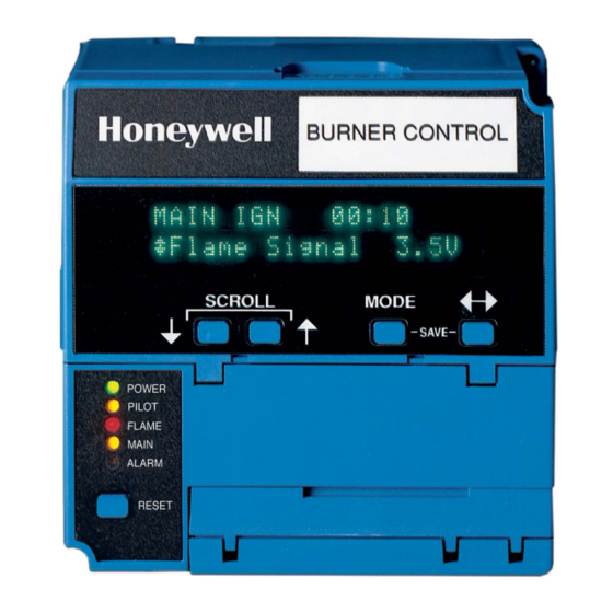
RM7838B,C
7800 SERIES Relay Module
APPLICATION
The Honeywell RM7838B,C is a microprocessor based
integrated burner control for industrial process
modulating semiautomatically fired gas, oil, coal or
combination fuel single burner applications. The
RM7838B,C System consists of a relay module, wiring
subbase, keyboard display module (KDM), amplifier, and
purge card. Options include Data ControlBus Module™,
remote display mounting, and first-out expanded
annunciator.
Functions provided by the RM7838B,C include automatic
modulated High Fire and Low Fire proven Purge, burner
pilot startup with pilot valve hold, a special pilot valve hold
from the Run condition, flame supervision, system status
indication, system or self-diagnostics and
troubleshooting.
The RM7838C differs from the RM7838B as follows:
1. Alarms only on Safety Shutdown.
2. Requires ST7800C Purge Timer.
3. C1004 has 15 second MFEP. C1020 has 5 second
MFEP.
This document covers the following 7800 Series Relay
Modules:
RM7838C1020
RM7838C2020
RM7838C1004
RM7838C2004
RM7838B1013
RM7838B2013
This document provides installation and static checkout
instructions. Other applicable publications are:
Form
Number
32-00110 S7800A2142 4-line LCD Keyboard Display
Module Product Data
32-00166 204729A/C KDM NEMA4 Covers for 4-line
LCD KDM
65-0084
Q7800A,B 22-Terminal Wiring Subbase
Product Data
65-0089
ST7800A Plug-In Purge Timer Installation
Instructions.
65-0090
S7800A Keyboard Display Module Product
Data.
RM7838C1020 and
RM7838C2020 only
Description
SIL
3
Capable
0063
INSTALLATION INSTRUCTIONS
Form
Number
65-0101
S7830 Expanded Annunciator Product Data.
65-0109
R7824, R7847, R7848, R7849, R7851, R7861,
R7886 Flame Amplifiers for the 7800 SERIES
Product Data.
65-0131
221818A Extension Cable Assembly Product
Data
65-0229
7800 Series Relay Modules Checkout and
Troubleshooting Product Data
65-0249
S7810M ModBus Module (For CE , Modbus
module S7810M1029 only).
65-0295
50023821-001/2 KDM NEMA4 Covers for
classic 2-line VFD KDM
SPECIFICATIONS
Electrical Ratings (See Table 4):
Voltage and Frequency: 120 Vac (+10/-15%),
50/60 Hz (±10%).
Power Dissipation:
RM7838B,C: 10W maximum.
Maximum Total Connected Load: 2000 VA.
Fusing Total Connected Load: 15A maximum, type SC or
equivalent, fast blow.
Environmental Ratings:
Ambient Temperature:
Operating: -40°F to +140°F (-40°C to +60°C).
Storage: -40°F to +150°F (-40°C to +66°C).
Humidity: 85% relative humidity continuous, noncon-
densing.
Vibration: 0.5G environment.
SIL 3 Capable:
SIL 3 Capable in a properly designed Safety Instrumented
System. See form number 65-0312 for Certificate
Agreement.
Description
32-00199-01
Advertisement
Table of Contents

Related Manuals for Honeywell 7800 Series


Summary of Contents for Honeywell 7800 Series
- Page 1 3. C1004 has 15 second MFEP. C1020 has 5 second Power Dissipation: MFEP. RM7838B,C: 10W maximum. This document covers the following 7800 Series Relay Maximum Total Connected Load: 2000 VA. Modules: Fusing Total Connected Load: 15A maximum, type SC or RM7838C1020 equivalent, fast blow.
-
Page 2: Installation
Gas Appliances Regulation: 2016/426/EU GAR age) wiring. Low Voltage Directive: 2014/35/EU LVD. 4. Loads connected to the 7800 SERIES Relay Mod- EMC Directive: 2014/30/EU EMC (Immunity Emission ule must not exceed those listed on the 7800 conformity can only be verified in combination with SERIES Relay Module label or the Specifications;... -
Page 3: Mounting Wiring Subbase
RM7838B,C 7800 SERIES RELAY MODULE Weather newly purchased. This includes (Q7800A1005 Q7800B1003), and the 2000 Series subbases The relay module is not designed to be weather tight. (Q7800A2005, Q7800B2003). When installed outdoors, protect the relay module in an approved weather-tight enclosure. -
Page 4: Wiring Subbase
RM7838B,C 7800 SERIES RELAY MODULE Wiring Subbase c. Enclose flame detector leadwires without armor cable in metal cable or conduit. d. Follow directions in flame detector, Data ControlBus Module™, or Remote Reset Module WARNING Instructions. Electrical Shock Hazard. 7. KDM: Because the KDM is powered from a low... - Page 5 RM7838B,C 7800 SERIES RELAY MODULE BURNER CONTROL (HOT) 120 Vac 50/60 HZ RECIRCULATING BLOWER PLUG-IN PURGE TIMER CARD CONFIGURATION TEST JUMPERS JACK FLAME SIGNAL RUN/TEST SWITCH PLUG-IN FLAME MICROCOMPUTER AMPLIFIER TEST RESET PUSHBUTTON RELAY DRIVE RELAY CIRCUIT STATUS FEEDBACK AND LINE...
- Page 6 RM7838B,C 7800 SERIES RELAY MODULE BURNER HOT N CONTROL PLUG-IN PURGE CONFIGURATION TIMER CARD JUMPERS TEST F L A M E S IG N A L JACK RECIRCULATING RUN/TEST BLOWER SWITCH P L U G -IN PLUG-IN MICROCOMPUTER F L A M E...
- Page 7 RM7838B,C 7800 SERIES RELAY MODULE Table 1. Recommended Wire Sizes and Part Numbers. Application Recommended Wire Size Recommended Part Numbers Line voltage terminals TTW60C, THW75C, THHN90C. 14, 16 or 18 AWG (0.75, 1.5 or 2.5 mm ) copper conductor, 600 volt insulation, moisture-resistant wire.
-
Page 8: Final Wiring Check
RM7838B,C 7800 SERIES RELAY MODULE FINAL WIRING CHECK Equipment Recommended Voltmeter (1M ohm/volt minimum sensitivity) set on the 1. Check the power supply circuit. The voltage and fre- 0-300 Vac scale and two jumper wires; using No. 14 wire, quency tolerance must match those of the insulated, 12 in. - Page 9 RM7838B,C 7800 SERIES RELAY MODULE Table 3. Static Checkout. Test Test If Operation is Abnormal, Check These Jumpers Voltmeter Normal Operation Items None 4-L2 Line voltage at terminal 4. 1. Master Switch. 2. Power Connected to the Master Switch. 3. Overload protection (fuse, circuit breaker, etc) has not opened the power line.
- Page 10 RM7838B,C 7800 SERIES RELAY MODULE Table 3. Static Checkout. (Continued) Test Test If Operation is Abnormal, Check These Jumpers Voltmeter Normal Operation Items 1. Firing rate control. 13-15 None Adjust firing rate control and watch tracking 2. Firing rate motor and transformer.
- Page 11 RM7838B,C 7800 SERIES RELAY MODULE Table 5. Combinations for Terminals 8, 9, and 10. Pilot Fuel 8 Main 9 Ignition 10 No Load No Load No Load No Load Jumper Terminals 8 to 9 for direct spark ignition. Table 6. Composition of Each Combination.
- Page 12 See Table 2. 2000 VA maximum connected load to relay module. Honeywell has tested this output at 9.8A at PF = 0.5, 58.A inrush for 100,000 cycles Total load current, excluding Burner/Boiler Motor and Firing Rate Outputs cannot exceed 5A, 25A inrush.
- Page 13 RM7838B,C 7800 SERIES RELAY MODULE SERIES 90 (HOT) MASTER FIRING RATE SERIES 90 RECIRCULATING Q7800 SUBBASE SWITCH MOTOR CONTROLLER BLOWER HIGH FIRE COMMON BURNER DPST ALARM CONTROL SILENCING SWITCH LOW FIRE 120V ALARM RECIRCULATING COMBUSTION MODULATE BLOWER AFS (L1) PILOT VALVE...
- Page 14 RM7838B,C 7800 SERIES RELAY MODULE (HOT) MASTER SERIES 90 RECIRCULATING SWITCH FIRING RATE SERIES 90 Q7800 SUBBASE BLOWER MOTOR CONTROLLER HIGH FIRE BURNER CONTROL COMMON DPST ALARM SILENCING SWITCH LOW FIRE 120V ALARM RECIRCULATING COMBUSTION MODULATE BLOWER AFS (L1) PILOT VALVE...
-
Page 15: Mounting Rm7838B,C Relay Module
RM7838B,C 7800 SERIES RELAY MODULE BURNER CONTROL Q7800 RECIRCULATING BLOWER HIGH FIRE COMMON – – MODULATE ALARM LOW FIRE COMBUSTION BLOWER RECIRCULATING STOP BLOWER AFS COMBUSTION BLOWER AFS LOW FIRE START SWITCH INTERMITTENT/10 SECOND HIGH PURGE RATE SWITCH INTERRUPTED PILOT/... - Page 16 RM7838B,C 7800 SERIES RELAY MODULE WIRING SUBBASE (Q7800A1005 plastic panel mount version) RUN/TEST SWITCH H O N E Y W E LL RELAY MODULE CONFIGURATION JUMPERS PURGE TIMER SEQUENCE STATUS LED PANEL POWE R RESET PILOT BUTTON FLAM E MAIN...
-
Page 17: Principal Technical Features
RM7838B,C 7800 SERIES RELAY MODULE PRINCIPAL TECHNICAL Purge card is not installed or removed. g. Purge card is bad. FEATURES 6. MAIN FLAME ESTABLISHING Period (MFEP) a. Low Fire Switch opens. b. Lockout Interlock opens . The RM7838B,C provides all customary flame safeguard c. - Page 18 RM7838B,C 7800 SERIES RELAY MODULE Standby 1. Pilot Flame Establishing Period (PFEP): a. When the PFEP begins: The RM7838B,C remains in STANDBY until the Burner (1) The pilot valve and ignition transformer, Control Switch is closed. Two seconds before leaving terminals 8 and 10, are energized.
- Page 19 RM7838B,C 7800 SERIES RELAY MODULE Pilot Valve Hold can also be used to hold the burner at the end of PFEP if configuration jumper JR3 was clipped. 1. The RM7838B,C releases the firing rate motor to modulation (terminals 13 and 15 are closed)
- Page 20 RM7838B,C 7800 SERIES RELAY MODULE Keyboard Display Module a. Current status of the burner sequence (STANDBY, PURGE, PILOT IGN, MAIN IGN and RUN). The KDM (see Fig. 8) is provided with the RM7838B,C b. Timing information (PURGE, PILOT IGN and Relay Module.
- Page 21 RM7838B,C 7800 SERIES RELAY MODULE DISPLAY INITIATE PURGE START PFEP MFEP POWER POWER POWER POWER POWER POWER POWER PILOT PILOT PILOT PILOT FLAME FLAME FLAME FLAME MAIN MAIN MAIN MAIN ALARM ALARM ALARM ALARM 10 SEC 5 SEC STANDBY PURGE...
- Page 22 RM7838B,C 7800 SERIES RELAY MODULE Fig. 10. RM7838B,C Relay Module operation (using pilot valve hold) (not RM7838C1020/RM7838C2020). 32-00199—01...
-
Page 23: Settings And Adjustments
RM7838B,C 7800 SERIES RELAY MODULE The extreme right side of the first line is either blank or 3. In Purge Drive to Low Fire position, the Run/Test shows a small arrow pointing to the second line followed Switch, when placed in the TEST position, holds the... -
Page 24: Safety And Security
Fault 110 and a lockout. Copying and reverse engineering is prohibited by the law. For More Information The Honeywell Thermal Solutions family of products includes Honeywell Combustion Safety, Eclipse, Exothermics, Hauck, Kromschröder and Maxon. To learn more about our products, visit ThermalSolutions.honeywell.com or contact your...