Table of Contents
Advertisement
Quick Links
Advertisement
Table of Contents
Troubleshooting

Related Manuals for GE Transport Pro


Summary of Contents for GE Transport Pro
- Page 1 ™ Transport Pro Patient Monitor Service Manual 2012659-002 Revision A...
- Page 2 127( Due to continuing product innovation, specifications in this manual are subject to change without notice. Listed below are GE Medical Systems Information Technologies trademarks used in this document. All other trademarks contained herein are the property of their respective owners.
-
Page 3: Table Of Contents
The Transport Pro Monitor ........ - Page 4 Connectors ............3-8 Connect the Transport Pro Monitor to the Tram Module ....3-8 Power Up .
- Page 5 Error Logs ............5-20 Revision A Transport Pro Patient Monitor 2012659-002...
- Page 6 Transport Pro Monitor ........
-
Page 7: Introduction
Introduction Revision A Transport Pro Patient Monitor 2012659-002... - Page 8 For your notes Transport Pro Patient Monitor Revision A 2012659-002...
-
Page 9: Manual Information
The display only. This does not include the Tram chute or the Tram module. Intended Audience This manual is intended for service representatives and technical personnel who maintain, troubleshoot, or repair this equipment. Revision A Transport Pro Patient Monitor 2012659-002... -
Page 10: Safety Information
Introduction: Safety Information Safety Information Responsibility of the Manufacturer GE is responsible for the effects of safety, reliability, and performance only if: Assembly operations, extensions, readjustments, modifications, or repairs are carried out by persons authorized by GE. The electrical installation of the relevant room complies with the requirements of the appropriate regulations. -
Page 11: Warnings, Cautions, And Notes
CAUTION indicates a potential hazard or unsafe practice which, if not avoided, could result in minor personal injury or product/property damage. NOTE provides application tips or other useful information to assure that you get the most from your equipment. Revision A Transport Pro Patient Monitor 2012659-002... -
Page 12: Equipment Symbols
Type B equipment; type B equipment is suitable for intentional external and internal application to the patient, excluding direct cardiac application. Alternating current (AC) Battery 592A DC power 833A Ethernet 593A Video In 834A POWER 814A NBP GO/STOP 816A Transport Pro Patient Monitor Revision A 2012659-002... - Page 13 Introduction: Equipment Symbols ZERO ALL 817A SILENCE ALARM/ADMIT 818A Medical Equipment With respect to electric shock, fire and mechanical hazards only in accordance with UL 2601-1, and CAN/CSA C22.2 NO. 601.1. 4P41 Revision A Transport Pro Patient Monitor 2012659-002...
-
Page 14: Service Information
Any unauthorized attempt to repair equipment under warranty voids that warranty. It is the user’s responsibility to report the need for service to GE or to one of their authorized agents. Failure on the part of the responsible individual, hospital, or... -
Page 15: Equipment Overview
Equipment Overview Revision A Transport Pro Patient Monitor 2012659-002... - Page 16 For your notes Transport Pro Patient Monitor Revision A 2012659-002...
-
Page 17: Equipment Description
An asynchronous communication port is provided for communications with the Tram module. Unity Network (twisted-pair Ethernet) hardware is provided on the display, but Unity Network functionality is not available in V1A. The Transport Pro monitoring system consists of the following components: Transport Pro display/processing unit Tram module Tram chute Data cable (“curly”... -
Page 18: Optional Components
If the battery fails to meet the target performance, the battery charger will prompt you to condition the battery. If the battery does not hold a charge, then the battery charger will illuminate a “fail” light. Transport Pro Patient Monitor Revision A 2012659-002... -
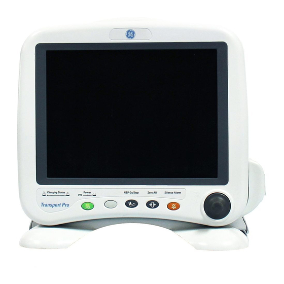
Page 19: Front View
“Controls” on page 2-8. The indicators provide information about the power source and the charging status of the batteries. See “Indicators” on page 2-8. Revision A Transport Pro Patient Monitor 2012659-002... -
Page 20: Back View
Use the mounting points to attach a standard IV pole clamp. Tram chute mounting slots Insert and slide the Tram chute mounting tabs. Be sure to insert and secure the Tram chute mounting screw. Transport Pro Patient Monitor Revision A 2012659-002... -
Page 21: Side Views
Data cable channel Place the Tram module data cable in the channel to reduce cable clutter. DC power connector “Connectors” on page 3-8. Battery doors Open the battery doors to insert and remove the batteries. Revision A Transport Pro Patient Monitor 2012659-002... -
Page 22: Controls
Function Keys Three fixed function keys are provided for NBP GO/STOP, ZERO ALL, and SILENCE ALARM/ADMIT. See the Transport Pro Operator’s Manual for a description. Indicators Power and battery indicators are also located on the front panel of the monitor. - Page 23 Neither indicator illuminates when the monitor is operating from both batteries simultaneously (i.e., in a very low battery charge condition when both batteries are joined together in order to sustain operation of the monitor). Revision A Transport Pro Patient Monitor 2012659-002...
-
Page 24: Tram Module Compatibility
3,5, or 10 lead ECG, Respiration, Cardiac Output or Dual temperature, NIBP, Ohmeda/ GEMS-IT SpO2 Tram 850 A SL T850SL=A 3,5, or 10 lead ECG, Respiration, Cardiac Output or Dual temperature, NIBP, Nellcor/ GEMS-IT SpO2 2-10 Transport Pro Patient Monitor Revision A 2012659-002... - Page 25 3,5, or 10 lead ECG, Respiration, Cardiac Output or Dual temperature, NIBP, Masimo SET SpO2 Tram 851N T851N=X 3,5, or 10 lead ECG, Respiration, Cardiac Output or Dual temperature, NIBP, Nellcor Oxismart XL SpO2 Revision A Transport Pro Patient Monitor 2-11 2012659-002...
-
Page 26: Theory Of Operation
This architecture results in an efficient and compact system by reducing the number of conversions required and optimizing the physical size of each converter for the specific application. 2-12 Transport Pro Patient Monitor Revision A 2012659-002... -
Page 27: Processor/Power Management Circuit Board Assembly
300 to 700 VRMS. The start voltage is 1400 VRMS and the lamp current is 7 milliamps per tube. Speaker The speaker is used for audible notification of alarms. It is 66mm square, water-resistant, 3 watt, with a frequency response of 400Hz to 4500Hz. Revision A Transport Pro Patient Monitor 2-13 2012659-002... - Page 28 Equipment Overview: Theory of Operation For your notes 2-14 Transport Pro Patient Monitor Revision A 2012659-002...
-
Page 29: Installation
Installation Revision A Transport Pro Patient Monitor 2012659-002... - Page 30 For your notes Transport Pro Patient Monitor Revision A 2012659-002...
-
Page 31: Requirements
Do not install the monitor in a location where it may drop on the patient. All consoles and brackets used must have a raised edge at the front. Revision A Transport Pro Patient Monitor 2012659-002... -
Page 32: Tools
Tools A standard set of hand tools is required to install the patient monitor. Mounting Options See the “Transport Pro Patient Monitor Bedrail Hook and IV Pole Mounting Kit Installation Instructions” for the mounting options available for this monitor. Transport Pro Patient Monitor... -
Page 33: Install Or Remove The Tram Chute
3. Slide the Tram chute to the left to capture the mounting tabs in the mounting slots. 4. Tilt the unit back and use a Phillips-head screwdriver to install the Tram chute mounting screw. Revision A Transport Pro Patient Monitor 2012659-002... - Page 34 3. Slide the Tram chute to the right to release the mounting tabs from the display. 4. Remove the Tram chute from the back of the display. 5. Install and store the screw in the Tram chute to prevent it from getting lost. Transport Pro Patient Monitor Revision A 2012659-002...
-
Page 35: Install Or Remove A Module
15 cm (six inches). 3. Once released, grasp the module firmly with both hands and remove the rest of the way. Do not try to hold the module by the release levers. Revision A Transport Pro Patient Monitor 2012659-002... -
Page 36: Connections
Tram module, and charges the monitor’s batteries. Connect the Transport Pro Monitor to the Tram Module Insert the “curly” data cable into the display’s Video In connector and into the Tram module’s DISPLAY connector. The Tram module’s DISPLAY connector is located on the front of the Tram module. -
Page 37: Power Up
After making all of the connections, plug the external power supply into an AC wall outlet. All front panel indicators will illuminate until the power-up sequence is complete. After approximately 10 seconds you should see a display on the screen. Revision A Transport Pro Patient Monitor 2012659-002... -
Page 38: Setup/Configure The Monitor
4. Rotate Trim Knob control to select the type of environment the monitor will be used in. 5. Press Trim Knob control to exit. Your selection displays at the top of the screen after the time. 3-10 Transport Pro Patient Monitor Revision A 2012659-002... -
Page 39: Set Monitor Defaults Password
4. Use the Trim Knob control to select and change each character. Up to seven characters may be entered. 5. Select SET UNIT NAME and press the Trim Knob control to exit. Revision A Transport Pro Patient Monitor 3-11 2012659-002... -
Page 40: Set Bed Number
5. Select SET BED NUMBER and press the Trim Knob control to exit. Set Country Selection Select DEFAULT or FRANCE to choose a particular set of GE factory defaults. 1. Activate the Boot Loader program. -
Page 41: Set Language
Press and release the Trim Knob control. a. Release NBP GO/STOP and ZERO ALL. Completion The monitor is now ready for normal operation. At this time, perform the “Checkout Procedure” on page 4-24. Revision A Transport Pro Patient Monitor 3-13 2012659-002... -
Page 42: Installing Software
Installation: Installing Software Installing Software The monitor leaves the factory with software installed. If you need to re- install software at any time, see the Transport Pro Patient Monitor Software Installation Instructions. These instructions are provided with the software Installation CD ROM. -
Page 43: Maintenance
Maintenance Revision A Transport Pro Patient Monitor 2012659-002... - Page 44 For your notes Transport Pro Patient Monitor Revision A 2012659-002...
-
Page 45: Maintenance Schedule
The manufacturer does not, in any manner, assume the responsibility for performing the recommended maintenance schedule, unless an Equipment Maintenance Agreement exists. The sole responsibility rests with the individuals, hospitals, or institutions utilizing the device. Revision A Transport Pro Patient Monitor 2012659-002... -
Page 46: Visual Inspection
Have any damaged connectors or cables replaced by qualified service personnel. Inspect the display face for marks, scratches, or other damage. Have the LCD replaced by qualified service personnel if necessary. Safety labels and inscription on the device are clearly legible. Transport Pro Patient Monitor Revision A 2012659-002... -
Page 47: Cleaning
In general you will need to use a soft, clean, lint-free cloth dampened with a glass cleaner. &$87,21 To avoid getting liquid into connector openings, do not spray glass cleaning or general cleaning solutions directly onto the product’s surface. Revision A Transport Pro Patient Monitor 2012659-002... -
Page 48: Lithium-Ion Battery
Conditioning Guideline Remove the battery from the monitor every six months and condition it using the Cadex SMart Two+ charger. This condition cycle recalibrates the electronic fuel gauge. Transport Pro Patient Monitor Revision A 2012659-002... -
Page 49: How To Identify The Capacity Of The Battery
When the battery is stored inside a monitor that is continuously powered by an AC power source and is not powered by battery on a regular basis, the life of the battery may be less than 12 months. GE recommends that you remove the battery and store it near the monitor until it is needed for transport. - Page 50 If after the condition cycle has been completed, the battery does meet the target performance, then the battery charger will illuminate a “fail” light. Or, if the battery is not performing to the target capacity, the battery charger will illuminate a “fail” light. Transport Pro Patient Monitor Revision A 2012659-002...
- Page 51 RETURN — Returns to the Battery Status menu. SLOT STATUS — Provides definitions of the battery conditions. ‹ No Battery — No battery is installed in this slot. ‹ Initializing — Battery is just installed, establishing Revision A Transport Pro Patient Monitor 2012659-002...
- Page 52 10 minutes per battery run time remaining. The monitor will issue a System Warning alarm when shutdown is imminent (less than one minute left of remaining run time). 4-10 Transport Pro Patient Monitor Revision A 2012659-002...
-
Page 53: How To Replace The Battery
5. Verify that the monitor operates correctly. a. Confirm that the battery icon is displayed in the lower right corner of the monitor. b. Verify the green or amber battery CHARGING STATUS LED is illuminated. Revision A Transport Pro Patient Monitor 4-11 2012659-002... -
Page 54: How To Charge The Battery
Inside a monitor that is connected to an AC power source. 127( To extend the life of the battery, GE recommends that you charge the battery using the external Cadex SMart Two+ charger. Charging the Battery With a Cadex SMart Two+ Charger 1. -
Page 55: How To Condition The Battery
Outside of a monitor by using the Cadex SMart Two+ charger. Inside a monitor that is connected to an AC power source. 127( To extend the life of the battery, GE recommends that you condition the battery using the external Cadex SMart Two+ charger. -
Page 56: How To Store The Battery
Watch the battery charger LEDs. The RUN LED should stop flashing and remain illuminated for approximately one minute later the CONDITION LED should stop flashing. At this time, the battery is awake and being charged. 4-14 Transport Pro Patient Monitor Revision A 2012659-002... -
Page 57: How To Recycle The Battery
Remove the old battery from the monitor and follow your local recycling guidelines. :$51,1* EXPLOSION HAZARD — DO NOT incinerate the battery or store at high temperatures. Serious injury or death could result. Revision A Transport Pro Patient Monitor 4-15 2012659-002... -
Page 58: The Cadex Smart Two+ Charger
Battery fault. Charger fault. FAIL and CONDITION Conditioning is complete — fail target. Battery Charger Software Requirements The batteries used in this monitor require Cadex SMart Two+ Charger software version 1.1 or later. 4-16 Transport Pro Patient Monitor Revision A 2012659-002... -
Page 59: Electrical Safety Tests
Electrical safety tests provide a method of determining if potential electrical health hazards to the patient or operator of the device exist. Recommendations GE recommends that you perform all safety tests presented in this chapter. upon receipt of the device (monitor and its associated equipment),... -
Page 60: Power Outlet Test
If other than normal polarity and ground is indicated, corrective action must be taken before proceeding. The results of the following tests will be meaningless unless a properly wired power outlet is used. 4-18 Transport Pro Patient Monitor Revision A 2012659-002... -
Page 61: Ground (Earth) Integrity
This test normally is only required as a manufacturing production test to receive safety agency compliance (i.e. IEC601-1). Some country agency's do require this test after field equipment repairs (i.e. Germany's DIN VDE 0751 standards). Consult your country/local safety agency if in question. Revision A Transport Pro Patient Monitor 4-19 2012659-002... - Page 62 Video In connector which is protectively earthed shall not exceed 0.2 ohms. When taking this measurement, move the unit’s power cord around. There should be no fluctuations in resistance. 4-20 Transport Pro Patient Monitor Revision A 2012659-002...
-
Page 63: Ground (Earth) Wire Leakage Current Tests
7. Read the current leakage indicated on DMM. 127( If either reading is greater than the appropriate specification below, the device under test fails. Contact GE Medical Systems Information Technologies Technical Support. ‹ 300 µA (0.3 volts on the DMM), and the device under test is powered from 100-120 V/50-60 Hz ‹... -
Page 64: Enclosure Leakage Current Test
6. Read the current leakage indicated on DMM. 127( If either reading is greater than the appropriate specification below, the device under test fails. Contact GE Medical Systems Information Technologies Technical Support. • 300 µA (0.3 volts on the DMM), and the device under test is powered from 100-120 V/50-60 Hz •... -
Page 65: Test Completion
127( If the reading is greater than the specification below, and the device under test is powered from 100-240 V/50-60 Hz, the device under test fails. Contact GE Medical Systems Information Technologies Technical Support. ‹ 100 microamperes (0.1 volts on the DMM), and the device under test is powered from 100-240 V/50-60 Hz 11. -
Page 66: Checkout Procedure
Item Part Number/Model Tram 100-851N module GE Medical Systems Information Technologies; any model Multifunctional Micro-simulator MARQ-1 Oscilloscope Tektronix 2215 External power supply for the monitor PN 2012183-001 Known good battery PN 419068-004 4-24 Transport Pro Patient Monitor Revision A 2012659-002... -
Page 67: Monitor Power-Up Tests
Pull that battery out and verify the other LED illuminates, thus indicating the unit is powered by the other battery. Reinstall battery and plug the monitor into an AC power source. Revision A Transport Pro Patient Monitor 4-25 2012659-002... -
Page 68: Battery Tests
3. Insert a Tram module into the Tram chute. 4. Connect the Tram communication cable to the Transport Pro monitor and verify an ECG parameter box is displayed on the monitor screen. This indicates the Tram module can be run from battery power. - Page 69 4 = 0407). 2. Select BATTERY SERVICE to display the Battery Service window and review the battery data. 861A 3. If necessary, condition the battery. See “How to Condition the Battery” on page 4-13. Revision A Transport Pro Patient Monitor 4-27 2012659-002...
-
Page 70: Display Tests
2. Verify the speaker volume of the monitor changes accordingly. 3. Return the volume of the monitor to the level it was previously set to, before you changed it for this test. 4-28 Transport Pro Patient Monitor Revision A 2012659-002... -
Page 71: Tram Module Communication Test
PM form. On the following page a repair log is included for your convenience to record the repair history of this product. Revision A Transport Pro Patient Monitor 4-29 2012659-002... -
Page 72: Repair Log
Maintenance: Checkout Procedure Repair Log Unit Serial Number: Institution Name: Date Maintenance/Repair Technician 4-30 Transport Pro Patient Monitor Revision A 2012659-002... -
Page 73: Troubleshooting
Troubleshooting Revision A Transport Pro Patient Monitor 2012659-002... - Page 74 For your notes Transport Pro Patient Monitor Revision A 2012659-002...
-
Page 75: Required Tools/Special Equipment
A standard set of hand tools is required for disassembly and assembly. Digital Multimeter. A known good battery. For electrical safety test equipment, see “Test Equipment” on page 4- For checkout procedure tools and equipment, see “Required Tools/ Special Equipment” on page 4-24. Revision A Transport Pro Patient Monitor 2012659-002... -
Page 76: Diagnostic Tests
The following checkout procedures can also be used as diagnostic tests for the monitor: “Monitor Power-up Tests” on page 4-25. “Battery Tests” on page 4-26. “Display Tests” on page 4-28. “Speaker Test” on page 4-28. Transport Pro Patient Monitor Revision A 2012659-002... -
Page 77: Main Processor Board Leds
The following table identifies the meaning of the illuminated LEDs. Main Processor Board LEDs Color Description The Boot Code has loaded. yellow The Main Code has loaded. green There is communication with the Tram module. Revision A Transport Pro Patient Monitor 2012659-002... -
Page 78: Troubleshooting Procedures
Troubleshooting: Troubleshooting Procedures Troubleshooting Procedures Symptom: Blank Display 845A Transport Pro Patient Monitor Revision A 2012659-002... -
Page 79: Symptom: Dim Display
Troubleshooting: Troubleshooting Procedures Symptom: Dim Display 846A Revision A Transport Pro Patient Monitor 2012659-002... -
Page 80: Symptom: Poor Display Quality
Troubleshooting: Troubleshooting Procedures Symptom: Poor Display Quality 847A Transport Pro Patient Monitor Revision A 2012659-002... -
Page 81: Symptom: No Audible Alarms
Troubleshooting: Troubleshooting Procedures Symptom: No Audible Alarms 848A Revision A Transport Pro Patient Monitor 2012659-002... -
Page 82: Symptom: Unable To Lower Alarm Volume
Troubleshooting: Troubleshooting Procedures Symptom: Unable to Lower Alarm Volume 849A 5-10 Transport Pro Patient Monitor Revision A 2012659-002... -
Page 83: Symptom: Speaker Buzz
Troubleshooting: Troubleshooting Procedures Symptom: Speaker Buzz 850A Revision A Transport Pro Patient Monitor 5-11 2012659-002... -
Page 84: Symptom: Unresponsive Buttons
Troubleshooting: Troubleshooting Procedures Symptom: Unresponsive Buttons 851A 5-12 Transport Pro Patient Monitor Revision A 2012659-002... -
Page 85: Symptom: Monitor Resets
Troubleshooting: Troubleshooting Procedures Symptom: Monitor Resets 852A Revision A Transport Pro Patient Monitor 5-13 2012659-002... -
Page 86: Service Menus
“Set Language” on page 3-13. VIDEO TEST SCREENS This menu contains various color screens for testing the display. See “Display Tests” on page 4-28. BATTERY SIMULATION This option is for engineering use only. 5-14 Transport Pro Patient Monitor Revision A 2012659-002... - Page 87 1. Hold down NBP GO/STOP and ZERO ALL. 2. Press and release the Trim Knob control. 3. Release NBP GO/STOP and ZERO ALL. The monitor will boot up into normal mode. Revision A Transport Pro Patient Monitor 5-15 2012659-002...
-
Page 88: Service Mode Menu
Because of this, unnecessary tampering with service mode menu option items for experimentation purposes is not recommended by GE and may cause a malfunction of the monitor. The Service Mode menu is used for initial setup and configuration as well as for troubleshooting. - Page 89 See “Set Patient-Monitor Type” on page 3-10. :$51,1* Changing the patient-monitor type will default the admit function to Standard configuration. Different alarms and parameters are activated for each selection. Revision A Transport Pro Patient Monitor 5-17 2012659-002...
-
Page 90: Review Errors
Review Errors The Review Errors menu is an advanced troubleshooting tool used by GE engineering personnel. Some of the information recorded in the monitor error log can be useful for field service troubleshooting. - Page 91 Immediately after you clear one of the error logs, a message appears on the upper right side of the display. The message verifies the actuation of the Trim Knob control for this function. Revision A Transport Pro Patient Monitor 5-19 2012659-002...
-
Page 92: Error Log Information
These logs may be requested by Tech Support on occasion to aid in troubleshooting the monitor. The logs are developed to aid engineering for internal diagnostics of the monitor. Contact Tech Support if you need clarification of any of the error logs. 5-20 Transport Pro Patient Monitor Revision A 2012659-002... - Page 93 FORCED RESET The operating system restarted normally after a known condition, such as an Internet address change, patient discharge, etc. Revision A Transport Pro Patient Monitor 5-21 2012659-002...
-
Page 94: Battery Alarms And Messages
A serious failure has occurred while using or charging the battery. CHECK BATT STATUS System MESSAGE Charger Failure Charger communications have failed. 127( INTERNAL CHARGER FAILED, CALL SERVICE also appears in the Battery Status information window. 5-22 Transport Pro Patient Monitor Revision A 2012659-002... -
Page 95: Battery Error Message
The battery is either 1. See “How to Wake Up the Battery” on page 4-14. asleep or faulty. 2. If the battery does not “wake up” it is faulty and should be replaced. Revision A Transport Pro Patient Monitor 5-23 2012659-002... -
Page 96: Power Source Tests
Line to neutral: 120 VAC Line to ground: 120 VAC Neutral to ground: < 3 VAC Readings other than these indicate improper wiring. Have the wall receptacle checked by an electrician. 5-24 Transport Pro Patient Monitor Revision A 2012659-002... -
Page 97: Power Cord And Plug
Verify line, neutral, and ground conductors are properly connected to the power cord plug and are not short-circuited. Rewire and tighten these, or replace the power cord, as necessary. Revision A Transport Pro Patient Monitor 5-25 2012659-002... -
Page 98: Error Messages
“WARNING: The EEPROM data was found to be either INVALID or Following the EEPROM dump, restore data: uninitialized. GE factory defaults will be stored in both the EEPROM 1. Restore Ethernet address and IP address as requested by and the monitor’s configuration memory. You will be required to re- the Boot Code. - Page 99 These messages are displayed while the monitor monitor to monitor the patient. powers up. Once the “Internal lithium battery is 3. Contact GE Service for lithium battery replacement LOW” message appears, the monitor will complete instructions. all the power-up tests. Then, after the last test is The battery switch on main pcb may be in the off position.
- Page 100 Troubleshooting: Error Messages For your notes 5-28 Transport Pro Patient Monitor Revision A 2012659-002...
-
Page 101: Parts List, Drawings, And Replacement
Parts List, Drawings, and Replacement Revision A Transport Pro Patient Monitor 2012659-002... - Page 102 For your notes Transport Pro Patient Monitor Revision A 2012659-002...
-
Page 103: Ordering Parts
If you require additional information or troubleshooting assistance, contact Technical Support. To order parts, contact Service Parts at the address or telephone number listed on the “How to Reach Us...” page found in the front of this manual. Revision A Transport Pro Patient Monitor 2012659-002... -
Page 104: Service Parts
2014437-005 — software 2014437-006 — speaker assembly 864A 2014437-007 — inverter PCB and harness 865A 2014437-008 — foot 866A 2014437-009 — battery doors 867A 2014437-010 — collar 868A 2014437-011 — main PCB assembly 869A Transport Pro Patient Monitor Revision A 2012659-002... -
Page 105: Fru Parts Lists
CARTON MAILER W/FOAM 14.5 X 14.5 X 4.5 402440-001 SCREW PH PLASFORM #6-10 X . 9956-101 BAG ZIPLOCK CLR 2MIL POLY 3 2011633-001 LABEL KIT - TRANSPORT PRO FRONT ENG 2011633-002 LABEL KIT - TRANSPORT PRO FRONT GER 2011633-003 LABEL KIT - TRANSPORT PRO FRONT FRE 2011633-004... - Page 106 Find Reference Item Number Item Description Number Designator 2011633-010 LABEL KIT - TRANSPORT PRO FRONT JPN 2011633-011 LABEL KIT - TRANSPORT PRO FRONT POR 2011633-012 LABEL KIT - TRANSPORT PRO FRONT RUS 2011633-013 LABEL KIT - TRANSPORT PRO FRONT CHI...
- Page 107 CARTON MAILER W/FOAM 14.5 X 14.5 X 4.5 9956-101 BAG ZIPLOCK CLR 2MIL POLY 3 2000905-001 SCR TAPPING TC SST #4X.31 HI-LO 2011633-001 LABEL KIT - TRANSPORT PRO FRONT ENG 2011633-002 LABEL KIT - TRANSPORT PRO FRONT GER 2011633-003 LABEL KIT - TRANSPORT PRO FRONT FRE 2011633-004...
- Page 108 Find Reference Item Number Item Description Number Designator 2011633-007 LABEL KIT - TRANSPORT PRO FRONT DUT 2011633-008 LABEL KIT - TRANSPORT PRO FRONT DAN 2011633-009 LABEL KIT - TRANSPORT PRO FRONT NOR 2011633-010 LABEL KIT - TRANSPORT PRO FRONT JPN...
- Page 109 9924-102 BOX MAILER 7.00L 6.00W 2.50H 404525-001 LABEL BLANK 2 X 3/4 2001005-061 INSTR FIELD REPLACEMENT UNIT ENG 2017716-001 UPGRADE KIT TRANSPORT PRO V1A ENG Speaker Assembly — PN 2014437-006, Rev. A 864A Find Reference Item Number Item Description Number...
- Page 110 INSTR FIELD REPLACEMENT UNIT ENG 407132-008 LBL BARCODE CMPNT PA 1.6 X 404525-001 LABEL BLANK 2 X 3/4 9924-002 BOX CARDBOARD 4 X 4 X 3 9956-101 BAG ZIPLOCK CLR 2MIL POLY 3 6-10 Transport Pro Patient Monitor Revision A 2012659-002...
- Page 111 SCR MACH PNHD M3X6LG SST W/THD LOCK 9956-101 BAG ZIPLOCK CLR 2MIL POLY 3 2001005-061 INSTR FIELD REPLACEMENT UNIT ENG 404525-001 LABEL BLANK 2 X 3/4 9924-101 BOX MAILER 11.75L 11.00W 2.88H 9956-001 BAG ANTI-STATIC 12SQ 4MIL Revision A Transport Pro Patient Monitor 6-11 2012659-002...
- Page 112 404525-001 LABEL BLANK 2 X 3/4 9956-002 4X6IN ANTI-STATIC ZIPLOCK BAG 9956-101 BAG ZIPLOCK CLR 2MIL POLY 3 9924-002 BOX CARDBOARD 4 X 4 X 3 2001005-061 INSTR FIELD REPLACEMENT UNIT ENG 6-12 Transport Pro Patient Monitor Revision A 2012659-002...
- Page 113 2012181-001 COLLAR CABLE TRANSPORT DISPLAY 2013297-001 ADH VHB ETD 9956-001 BAG ANTI-STATIC 12SQ 4MIL 2001005-061 INSTR FIELD REPLACEMENT UNIT ENG 404525-001 LABEL BLANK 2 X 3/4 9924-101 BOX MAILER 11.75L 11.00W 2.88H Revision A Transport Pro Patient Monitor 6-13 2012659-002...
-
Page 114: Other Components
Item Number Item Description 2011432-001 Tram Chute 2012183-001 Optional External Power Supply 419068-004 Rechargeable Lithium Ion Battery 11.1V 2001845-001 Cadex SMart Two+ Battery Charger V1.11 421071-001 Lithium Ion Battery PC Mount 3V 6-14 Transport Pro Patient Monitor Revision A 2012659-002... -
Page 115: Interconnection Diagram
Parts List, Drawings, and Replacement: Interconnection Diagram Interconnection Diagram Revision A Transport Pro Patient Monitor 6-15 2012659-002... -
Page 116: Exploded Views
Parts List, Drawings, and Replacement: Exploded Views Exploded Views Transport Pro Display Assembly — PN 2012150-001, Rev. A Sheet 1 of 2 6-16 Transport Pro Patient Monitor Revision A 2012659-002... - Page 117 Parts List, Drawings, and Replacement: Exploded Views Sheet 2 of 2 Revision A Transport Pro Patient Monitor 6-17 2012659-002...
- Page 118 Parts List, Drawings, and Replacement: Exploded Views Parts List for Transport Pro Display Assembly — PN 2012150-001, Rev. A Find Item Number Item Description Reference Designator Number 2012147-001 ASSY EMERALD TRANSPORT DISPLAY A4,A5 2013150-001 ASSY PROCESSOR PCB TRANSPORT DISPLAY A1,A3...
-
Page 119: Transport Pro Display Tram Chute - Pn 2011432-001, Rev. A
Parts List, Drawings, and Replacement: Exploded Views Transport Pro Display Tram Chute — PN 2011432-001, Rev. A Revision A Transport Pro Patient Monitor 6-19 2012659-002... -
Page 120: Disassembly/Assembly Of Frus
127( GE recommends that you assemble the monitor using the NEW fasteners (screws, washers, etc.) provided in the Field Replaceable Unit kit. Some fasteners, like the screws with a thread locking coating, are NOT intended to be re-used more than three times. - Page 121 Handle all PCB assemblies by their edges. These guidelines may not guaranty a 100% static-free workstation, but can greatly reduce the potential for failure of any electrical/electronic assemblies being serviced. Revision A Transport Pro Patient Monitor 6-21 2012659-002...
-
Page 122: Disassembly Procedures
6. Lay both halves of the unit on a flat surface. To prevent damaging the Trim Knob control, ALWAYS hang the Trim Knob control over the edge of the work surface. 874A 6-22 Transport Pro Patient Monitor Revision A 2012659-002... - Page 123 Parts List, Drawings, and Replacement: Disassembly/Assembly of FRUs 7. Disconnect the battery harness from the main PCB and set the back half of the unit aside. 875A 875A Revision A Transport Pro Patient Monitor 6-23 2012659-002...
- Page 124 2. Remove the four screws holding the main PCB assembly to the display sub-assembly. 879A 3. Pull out friction connector from the inverter PCB. Do not pull on the connector wires. 878A 6-24 Transport Pro Patient Monitor Revision A 2012659-002...
- Page 125 881A 6. Remove the PCB and set it aside. 7. Place the display sub-assembly face-down with the Trim Knob control hanging over the edge of the work surface. Revision A Transport Pro Patient Monitor 6-25 2012659-002...
- Page 126 ALWAYS keep the display sub- assembly on a flat surface with the Trim Knob control hanging over the edge of the work surface. 862A 9. Insert the display friction connector into the main PCB connector. 881A 6-26 Transport Pro Patient Monitor Revision A 2012659-002...
- Page 127 Parts List, Drawings, and Replacement: Disassembly/Assembly of FRUs 10. Insert the keypad PCB connector into the keypad PCB. 880A 11. Tuck in the keypad PCB ribbon cable to prevent it from being damaged. 882a Revision A Transport Pro Patient Monitor 6-27 2012659-002...
- Page 128 13. Install four screws to secure the main PCB assembly to the display. 879A 14. Close the unit in reverse order that you opened it. See “Open the Unit” on page 6-22. 6-28 Transport Pro Patient Monitor Revision A 2012659-002...
- Page 129 2. Remove the four screws holding the main PCB assembly to the display sub-assembly. 879A 3. Pull out friction connector from the inverter PCB. Do not pull on the connector wires. 878A Revision A Transport Pro Patient Monitor 6-29 2012659-002...
- Page 130 881A 6. Remove the main PCB assembly and set it aside. 7. Place the display sub-assembly face-down with the Trim Knob control hanging over the edge of the work surface. 6-30 Transport Pro Patient Monitor Revision A 2012659-002...
- Page 131 9. Remove the LCD and rubber display isolator and set them aside. 888A 10. Install the LCD and rubber display isolator into the new display plastic. 11. Install the blank PCB and blank lens cover. Revision A Transport Pro Patient Monitor 6-31 2012659-002...
- Page 132 Parts List, Drawings, and Replacement: Disassembly/Assembly of FRUs 12. Insert the display friction connector into the main PCB connector. 881A 13. Insert the keypad PCB connector into the keypad PCB. 880A 6-32 Transport Pro Patient Monitor Revision A 2012659-002...
- Page 133 16. Install four screws to secure the main PCB assembly to the display. 879A 17. Close the unit in reverse order that you opened it. See “Open the Unit” on page 6-22. Revision A Transport Pro Patient Monitor 6-33 2012659-002...
- Page 134 2. Remove the four screws holding the main PCB assembly to the display sub-assembly. 879A 3. Pull out friction connector from the inverter PCB. Do not pull on the connector wires. 878A 6-34 Transport Pro Patient Monitor Revision A 2012659-002...
- Page 135 881A 6. Remove the main PCB assembly and place on a flat surface. 7. Place the display sub-assembly face-down with the Trim Knob control hanging over the edge of the work surface. Revision A Transport Pro Patient Monitor 6-35 2012659-002...
- Page 136 8. Remove the four nuts holding the speaker onto the main PCB assembly. 883A 9. Disconnect the speaker harness from the main PCB assembly. 10. Install the new speaker. 11. Insert the display friction connector into the main PCB connector. 881A 6-36 Transport Pro Patient Monitor Revision A 2012659-002...
- Page 137 Parts List, Drawings, and Replacement: Disassembly/Assembly of FRUs 12. Insert the keypad PCB connector into the keypad PCB. 880A 13. Tuck in the keypad PCB ribbon cable to prevent it from being damaged. 882a Revision A Transport Pro Patient Monitor 6-37 2012659-002...
- Page 138 15. Install four screws to secure the main PCB assembly to the display. 879A 16. Close the unit in reverse order that you opened it. See “Open the Unit” on page 6-22. 6-38 Transport Pro Patient Monitor Revision A 2012659-002...
- Page 139 2. Remove the four screws holding the main PCB assembly to the display sub-assembly. 879A 3. Pull out friction connector from the inverter PCB. Do not pull on the connector wires. 878A Revision A Transport Pro Patient Monitor 6-39 2012659-002...
- Page 140 881A 6. Remove the main PCB assembly and place on a flat surface. 7. Place the display sub-assembly face-down with the Trim Knob control hanging over the edge of the work surface. 6-40 Transport Pro Patient Monitor Revision A 2012659-002...
- Page 141 8. Remove the two screws holding the inverter board onto the main PCB assembly. 885A 9. Remove the backlight friction connector from the main PCB assembly. 885A 884A 10. Install the new inverter board onto the main PCB assembly. Revision A Transport Pro Patient Monitor 6-41 2012659-002...
- Page 142 Parts List, Drawings, and Replacement: Disassembly/Assembly of FRUs 11. Insert the display friction connector into the main PCB connector. 881A 12. Insert the keypad PCB connector into the keypad PCB. 880A 6-42 Transport Pro Patient Monitor Revision A 2012659-002...
- Page 143 15. Install four screws to secure the main PCB assembly to the display. 879A 16. Close the unit in reverse order that you opened it. See “Open the Unit” on page 6-22. Revision A Transport Pro Patient Monitor 6-43 2012659-002...
- Page 144 2. Remove the seven screws from the battery housing located in the back half of the unit. 876A = 4 large screws = 3 small screws 3. Remove the battery harness from the back half of the unit. remove harness 877A 6-44 Transport Pro Patient Monitor Revision A 2012659-002...
- Page 145 Parts List, Drawings, and Replacement: Disassembly/Assembly of FRUs 4. Remove the four screws holding the main PCB assembly to the display. 879A 5. Pull out friction connector from the inverter PCB. Do not pull on the connector wires. 878A Revision A Transport Pro Patient Monitor 6-45 2012659-002...
- Page 146 6. Squeeze the connector tabs and pull out the connector from the keypad PCB. 880A 7. Pull out the display friction connector from the main PCB. Do not pull on the ribbon cable. 881A 6-46 Transport Pro Patient Monitor Revision A 2012659-002...
- Page 147 When connecting the keypad PCB harness, be sure to tuck in the ribbon cable to prevent it from being damaged. 882a 11. Install four screws to secure the main PCB assembly to the display. 879A Revision A Transport Pro Patient Monitor 6-47 2012659-002...
- Page 148 13. Install the seven screws for the battery housing. 876A = 4 large screws = 3 small screws 14. Close the unit in reverse order that you opened it. See “Open the Unit” on page 6-22. 6-48 Transport Pro Patient Monitor Revision A 2012659-002...
- Page 149 1. Remove the two screws that attach the foot to the display. 2. Pull to slide the foot out of the display grooves. 3. Slide the new foot into place and install the screws. Revision A Transport Pro Patient Monitor 6-49 2012659-002...
- Page 150 2. Insert battery door B into the top position and battery door A into the bottom position. battery door B battery door A 844A 3. Insert and tighten the battery door screw. 6-50 Transport Pro Patient Monitor Revision A 2012659-002...
- Page 151 4. Place the collar on the edge of the display and slide the collar until it is in position. Press the collar firmly against the display to adhere the collar to the display. Revision A Transport Pro Patient Monitor 6-51 2012659-002...
-
Page 152: After Assembly
Front Plastic “Monitor Power-up Tests” on page 4-25. with Switch Assemblies FRU Speaker “Speaker Test” on page 4-28. Assembly FRU Foot Assembly None None Collar Assembly None None Battery Doors None None 6-52 Transport Pro Patient Monitor Revision A 2012659-002... -
Page 153: Appendix A - Technical Specifications
Appendix A – Technical Specifications 127( Due to continual product innovation, specifications are subject to change without notice. The following specifications are accurate as of the date of this publication, and pertain to the monitor. Revision A Transport Pro Patient Monitor 2012659-002... - Page 154 For your notes Transport Pro Patient Monitor Revision A 2012659-002...
-
Page 155: Product Specification
4 hours Battery life: 500 cycles to 50% capacity Environmental Specifications Power requirements: battery or external DC power supply Power consumption: 60W with Tram module connection (maximum) Cooling: convection Power Dissipation: 120 Btu/Hour (maximum) Revision A Transport Pro Patient Monitor 2012659-002... -
Page 156: Dc Power Supply
-40°C (-40°F) Batteries: -20°C to 60°C (-4°F t0 140°F) Product Durability Specifications Fluid ingress test Meets IEC 601-2-27 Drop test standard 76.2 cm (30 inches) Vibration test MIL-STD 810E Method 514.4, category 1 Transport Pro Patient Monitor Revision A 2012659-002... -
Page 157: Physical Specification
12.7 cm (5.0 inches) Weight 1.36 kg (3 lbs) without Tram module Certification UL 2601-1 classified. UL classified for CAN/CSA C22.2 No. 601.1 IEC 60601-1 certified CE marking for Council Directive 93/42/EEC Medical Device Directive Revision A Transport Pro Patient Monitor 2012659-002... - Page 158 Appendix A – Technical Specifications: Physical Specification For your notes Transport Pro Patient Monitor Revision A 2012659-002...
- Page 160 0459 gemedical.com Asia Headquarters European Representative World Headquarters GE Medical Systems GE Medical Systems GE Medical Systems Information Technologies Asia Information Technologies GmbH Information Technologies, Inc. 24th Floor, Shanghai MAXDO Center, Postfach 60 02 65 8200 West Tower Avenue NO. 8 Xing Yi Road, Hong Qiao...