
Related Manuals for GE ApexPro TT


Summary of Contents for GE ApexPro TT
- Page 1 GE Healthcare ApexPro™ Antenna Infrastructure, Transmitter, and Receiver Technical Manual ApexPro™ English 2028341-019 (cd) 2028340-042A (paper) © 2008 General Electric Company. All rights reserved.
- Page 2 Due to continuing product innovation, specifications in this manual are subject to change without notice. NOTE For technical documentation purposes, the abbreviation GE is used for the legal entity name, GE Medical Systems Information Technologies. Listed below are GE Medical Systems Information Technologies trademarks. All other trademarks contained herein are the property of their respective owners.
-
Page 3: Table Of Contents
Contents Introduction ....... . 1-1 Manual Information ..........1-2 Revision history . - Page 4 Install antenna amplifiers ........3-9 Install attenuators .
- Page 5 Antenna system troubleshooting ....... . . 5-7 ApexPro transmitter carrier impairment measurement procedure..5-9 Rationale for test .
- Page 6 Bandpass filters..........6-14 ApexPro bandpass filter 608-614 MHz .
- Page 7 Additional system tests........7-3 Transmitter checkout .
- Page 8 ApexPro receiver ..........A-12 Performance specifications .
- Page 9 2001989-351A ApexPro™...
- Page 10 viii ApexPro™ 2001989-351A...
-
Page 11: Introduction
Introduction 2001989-351A ApexPro™... -
Page 12: Manual Information
Ordering manuals A paper copy of this manual will be provided upon request. Contact your local GE representative and request the part number on the first page of the manual. Conventions... -
Page 13: Safety Information
Unity network to clinical information systems for display. Responsibility of the manufacturer GE is responsible for the effects of safety, reliability, and performance only if: assembly operations, extensions, readjustments, modifications, or repairs are carried out by persons authorized by GE;... - Page 14 The rating of protection against electric shock (indicated by symbol for CF) is achieved only when used with patient applied parts recommended by GE. TYPE B APPLIED PART: Non-isolated applied part suitable for intentional external and internal application to the patient excluding direct cardiac application.
-
Page 15: Safety Statements
Introduction Complies with IPX3 standards for water ingress Complies with IPX7 standards for water ingress This symbol indicates that the waste of electrical and electronic equipment must not be disposed as unsorted municipal waste and must be collected separately. Please contact an authorized representative of the manufacturer for information concerning the decommissioning of your equipment. - Page 16 FALSE CALLS—False low heart rate indicators or false asystole calls may result with certain pacemakers because of electrical overshoot. WARNING INTERFACING WITH OTHER EQUIPMENT —Contact GE for information before connecting any devices to the equipment that are not recommended in this manual. WARNING LOSS OF DATA —...
- Page 17 Introduction CAUTION ACCESSORIES (SUPPLIES) —To ensure patient safety, use only parts and accessories manufactured or recommended by GE. Parts and accessories used must meet the requirements of the applicable IEC 60601 series safety standards, and/or the system configuration must meet the requirements of the IEC 60601 medical electrical systems standard.
-
Page 18: Service Information
Any unauthorized attempt to repair equipment under warranty voids that warranty. It is the user’s responsibility to report the need for service to GE or to one of their authorized agents. Failure on the part of the responsible individual, hospital, or institution using this equipment to implement a satisfactory maintenance schedule may cause undue equipment failure and possible health hazards. -
Page 19: Equipment Identification
Introduction Equipment identification Every GE device has a unique serial number for identification. A sample of the information found on a serial number label is shown below. ### ## ## #### # # Description product code year manufactured fiscal week manufactured... - Page 20 Introduction 1-10 ApexPro™ 2001989-351A...
-
Page 21: Equipment Overview
Equipment Overview 2001989-351A ApexPro™... -
Page 22: System Overview
Equipment Overview System overview Overview A transmitter is directly connected to the patient and transmits monitored data via the antenna to a corresponding receiver in a one-to-one correspondence between transmitters and receivers. Up to 16 receivers (four quad receiver modules with four receivers on each) may reside in a receiver system. -
Page 23: Power Requirements
ApexPro receiver system. Equipment Unity Network The Unity Network is the networking system used to transmit information from one GE product to others connected to the same Unity Network. 2001989-351A ApexPro™... -
Page 24: Apexpro Antenna System
Equipment Overview ApexPro antenna system Antenna The antenna system is used for transmission of data from the transmitter to the receiver system. The antenna is a circularly-polarized array of sloping half-wave dipoles with an omni- directional coverage pattern. The antenna is available in two versions: active and passive. - Page 25 Identify antennas Identify the high-power and active antennas by the part number label and the GE logo only on the front (bottom). The passive antenna looks identical to the high-power antenna except it has a black cap over the LED power indicator.
-
Page 26: Enterprise Access Antenna System
Equipment Overview Design Part number Antenna type Description Status frequency 2000673-007 600 MHz ApexPro Active Antenna This active antenna operates within 608-614MHz. This antenna Current 608-614MHz also has a bandpass filter element that rejects signals outside of 608-614MHz, except for signals in channels 36 and 38. 2000673-008 450 MHz ApexPro Antenna Hi-Pwr... - Page 27 Equipment Overview 205A ApexPro CH Transmitter 207B CARESCAPE Telemetry T14 Transmitter NOTE In this manual, wherever the transmitter is shown, the ApexPro, ApexPro CH and T14 transmitter are valid, except where otherwise noted. Transmitter battery installation NOTE Refer to the ApexPro Telemetry System or the CARESCAPE Telemetry T14 Transmitter Operator’s Manual for further details on battery installation.
- Page 28 1 hour of reserve power before the unit shuts down. Battery functional life CAUTION GE recommends that you always replace both batteries at the same time. Re-using old batteries or using a combination of old and new batteries in the transmitter will compromise functionality of the transmitter and increase the risk of fire hazard.
-
Page 29: Transmitter Controls, Indicators And Labels
Equipment Overview Transmitter controls, indicators and labels Views The transmitters have the following buttons and LEDs: 605A, 207A, 206B ApexPro, ApexPro CH, and T14 Transmitters ApexPro ApexPro CH & T14 Function RL RA LA LL Va Vb RL RA LA LL Va Vb When first powered up, the lead LEDs flash rapidly, followed by two slow flashes. - Page 30 Equipment Overview ApexPro ApexPro CH & T14 Function When pressed, a 20-second graph strip is Graph printed on the writer or printer. (not available) When pressed, a blue border displays around the event bed and an alarm tone sounds at the CIC Pro center. The message Remote Event displays under the ECG parameter window for approximately ten seconds.It also generates a 20-second graph...
- Page 31 Equipment Overview Well for dust Location for attaching the set of dust covers. covers Dust covers Transmitters have a set of 2 dust covers, used when the interface connectors are not being used. Markings on the covers indicate the number of the interface connector port. Change The Change Battery LED flashes when battery power is running low and the batteries need changing.
-
Page 32: Transmitter Interfaces
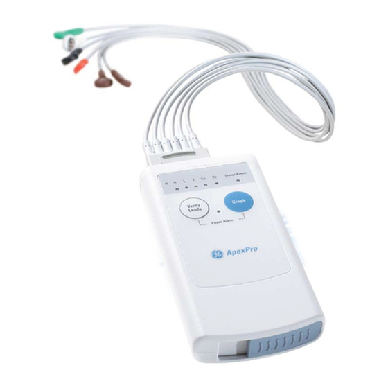
Equipment Overview T14 side labels The T14 transmitter also has side labels to distinguish it from an ApexPro CH transmitter. Additional side label kits may be ordered (See T14 on page 6-23.) Transmitter appearance ApexPro transmitters have 2 user buttons: Verify Leads and Graph. They have a white endcap on the end opposite the battery compartment cover. - Page 33 Equipment Overview RA shield functions as the RF antenna for the ApexPro and ApexPro CH transmitter; the T14 transmitter has an internal antenna. 317A Interface connector ports When enabled, interface connector ports provide an asynchronous communication connection to other devices (NBP, SpO2, etc.) for extra monitoring or for service connection to a programming box.
-
Page 34: Dinamap Pro Series Monitors
Equipment Overview When the battery voltage drops below 1.9 volts for ApexPro,1.6 volts for ApexPro CH or 1.73 volts for the T14, the Change Battery LED flashes once every second at a 1/8 duty cycle. The RF output is transmitted through one of the shield wires on the multi-link cables. The carrier frequency can be programmed to any frequency within the allowable band. -
Page 35: Apex Oximeter
Equipment Overview 310C NOTE The telemetry system supports 2 SpO2 oximeter modules: Apex Oximeter Nonin Xpod Oximeter Apex oximeter Theory of operation - pulse oximetry Pulse oximeters shine light (red and infrared) through perfused tissue and detect the fluctuating signals caused by arterial blood pressure pulses. Well-oxygenated blood is bright red, while poorly oxygenated blood is dark red. -
Page 36: Interconnection Cables
Equipment Overview SpO2 = O2Hb + COHb + MetHb SaO2 = 100 x O2Hb /(100 - COHb - MetHb) Where: SpO2 = Pulse oximeter determined and displayed oxygen saturation in percent O2Hb = Fractional oxyhemoglobin saturation in percent COHb = Carboxyhemoglobin saturation in percent MetHb = Methemoglobin saturation in percent SaO2 = Functional oxygen saturation in percent The following table gives examples of the oximeter readings:... -
Page 37: Apexpro Receiver System
Equipment Overview Plugs into the transmitter 423B Nonin Xpod oximeter The interconnection cables used to connect the transmitter and the SpO2 probe are a part of the oximeter module. Plugs into the Plugs into the Nonin SpO2 probe transmitter 502A ApexPro receiver system Overview The Receiver System receives RF signals from the four antenna inputs. - Page 38 Equipment Overview The RX network is directly connected by a network crossover cable to an ApexPro Telemetry System. The RX network should not be tied to any other network. rcrsysblk Receiver System Block Diagram Receiver subsystem (backplane) The subsystem provides an interface between the quad receiver modules and the telemetry software running on the ApexPro Telemetry System connected via 10BaseT Ethernet.
- Page 39 Equipment Overview Input/output connectors and signals F-Connectors, J1, J2, J3, and J4 Description Antenna A field input Antenna B field input Antenna C field input Antenna D field input RJ-45 Ethernet port, J6 Description HOST_XMIT_POS HOST_XMIT_NEG HOST_RCV_POS HOST_RCV_NEG RS-232 async comm port, J15 Description DGND 2001989-351A...
- Page 40 Equipment Overview Input power plug, J16 Description 2-20 ApexPro™ 2001989-351A...
-
Page 41: Installation And Configuration
Installation and configuration 2001989-351A ApexPro™... -
Page 42: Infrastructure Installation
Installation and configuration Infrastructure installation Overview This chapter provides direction for how to install specific parts and gives guidelines for specific tools to use for installation. Install coaxial cable Installation guidelines Use the hospital scaled prints and the logical antenna schematic to install the cabling. The logical antenna schematic is generated by ND&I. - Page 43 Installation and configuration Outer conductor or foil — Either solid aluminum tube or an aluminum foil wrap. The cable size is usually derived from its outside diameter. Braid — Interwoven strands of aluminum or copper mesh. It extends the conductivity of the outer conductor to the sleeve of the connector.
- Page 44 Installation and configuration Coaxial cable 205A Crimpers The typical hex crimping tool is shown below. The recommended crimping tool part numbers are the following. For RG-6 plenum, use a HCT-659 crimper from CablePrep. For RG-6 riser, use a CT611QS crimper from T&B. For RG-11 riser and plenum, use a CT611QS crimper from T&B (recommended) or HCT-211 crimper from CablePrep.
- Page 45 Installation and configuration 5/16 220A For this cable, use stripper 3CSK-GN from Cooper/Xcelite. The stripper requires 3 blades. To start with a squarely-cut cable end, open the stripper and place the cable so that 1/4 – 5/16 inch of cable extends past the first blade. Then close and latch the stripper and rotate around the cable 3 –...
- Page 46 Installation and configuration 1/4” 1/4” 222A For this cable, use stripper 3CSK-GN from Cooper/Xcelite. The stripper requires 2 blades. To start with a squarely-cut cable end, open the stripper and place the cable so that 1/4 – 5/16 inch of cable extends past the first blade. Then close and latch the stripper and rotate around the cable 3 –...
- Page 47 Installation and configuration 1/8” 1/2” 1-1/16” 225A For this cable, use stripper RG11 Maxi-Corex, 360. The stripper requires 3 blades. To start with a squarely-cut cable end, open the stripper and place the cable so that 1/4 – 5/16 inch of cable extends past the first blade. Then close and latch the stripper and rotate around the cable 3 –...
- Page 48 Installation and configuration RG-11 riser cable preparation Required stripping dimensions for the first cuts for the RG-11 riser cabling are shown below. 1/4” 1/2” 230A For RG-11 riser coaxial cable, use stripper RG11 Maxi-Corex, 360.To start with a squarely-cut cable end, open the stripper and place the cable so that 1/4 – 5/16 inch of cable extends past the first blade.
-
Page 49: Install Antennas
Installation and configuration Install antennas NOTE Be sure that after planning and designing the antenna system, the Penetration Check test (described in the ApexPro Antenna System Installation Test Instructions) is completed. It is used to estimate the RF penetration of the hospital construction. - Page 50 Installation and configuration To receiver system To antenna 245A Do not install antenna amplifiers backwards. Note the markings on the amplifier for installation orientation. If connected backwards, the LED will illuminate, however the amplifier will not work correctly; there will be signal loss instead of gain. Installing antenna amplifier here increases gain for only one antenna run.
-
Page 51: Install Attenuators
Installation and configuration Install attenuators Attenuators are used to attenuate the signal levels from the antennas. The locations of the attenuators and the types of attenuators used are determined by the ND&I team for each site installation. Installing an attenuator here attenuates one antenna run. -
Page 52: Install Notch/Bandpass Filters
Installation and configuration To antenna To receiver system 260A NOTE Do not install bias tees backwards. Note the markings on the bias tee for installation orientation. If connected backwards, the LEDs on all antennas and/or amplifiers in that specific antenna field run will not illuminate. Neither the antennas nor the amplifiers will work correctly. -
Page 53: Apexpro Receiver Installation
Installation and configuration With active antennas ApexPro Receiver Filter, System Notch, Bias Amplifier Splitter Unity MC Bandpass CIC Pro Center(s) +12 VDC 1A Power Supply 270B ApexPro receiver installation Due to the fact that frequency drift occurs even without power applied, the cailbration schedule should take into account the date the equipment was last calibrated, including equipment in storage locations and spares. -
Page 54: Connections
Installation and configuration RackMount CAUTION Mount the receiver system securely and away from vibration. Vibration may cause patient waveform dropout at the CIC. NOTE If using rack mount, route all cables to the hinge side so the receivers are accessible for service. A right angle F-connector may be helpful for the coaxial cable. -
Page 55: Setup Antenna Fields
Installation and configuration If the distance between the ApexPro Telemetry System and the Receiver System is less than 100 meters (328 ft.) use point-to-point with Ethernet crossover cable connection. If the distance is greater than 100 meters (328 ft.) then use either an additional hub or use fiber optic cable. - Page 56 Installation and configuration At the PC, use a communication program such as HyperTerminal to set up the ComPort connection. Port: Com1 (comm port on the PC) Speed: Baud 19200 Parity: Stop Bit: Data Bits: Flow Control: Xon Xoff Press Enter to get the @> Enter Service Password: prompt. Type password, mms_aps (case-sensitive).
-
Page 57: Setup The Receiver
Installation and configuration Setup the receiver Assuming that the ApexPro Telemetry System and all antennas have been installed and set up, the entire system is now installed and connected. CAUTION Equipment damage. If receiver system software needs updating, the system LED flashes yellow while software is updating. DO NOT power down the system during a software update. -
Page 58: Programming The Transmitter For Use
Installation and configuration Before installation, determine and record the date of initial factory calibration of transmitters and installation calibration is not within 30 months of the date shown on the manufacturer calibration sticker, calibrate before installation.See Calibration on page 4-10. Programming the transmitter for use Before use, the transmitter must be programmed. -
Page 59: Manually View/Program Ttx
Installation and configuration Transmitter Model(s) Parameter Status ApexPro, ApexPro CH, T14 TTX / Frequency Read / Write ApexPro, ApexPro CH, T14 Board Version Read ApexPro, ApexPro CH, T14 Synthesizer Lock Error Log Read / Clear ApexPro, ApexPro CH, T14 EEPROM Checksum Error Log Read / Clear ApexPro, ApexPro CH, T14 Synthesizer Lock Status... - Page 60 Installation and configuration The first 4 LEDs light up indicating it is going to display the 4-digit TTX number. The RA LED flashes a number of times corresponding to the first digit of the TTX number. The flashes are from 1 to 10, with 10 flashes representing a zero digit.
- Page 61 Installation and configuration Proceed to the next digit by pressing the Graph button until the next LED flashes. Repeat for all 4 (5 for T14 transmitter) digits. The TTX number is not changed until the fourth/fifth digit is accepted by pressing the Graph button.
- Page 62 Installation and configuration 3-22 ApexPro™ 2001989-351A...
-
Page 63: Maintenance
Maintenance 2001989-351A ApexPro™... -
Page 64: Apexpro Ch Telemetry Tune-Up
Maintenance ApexPro CH Telemetry Tune-Up Introduction To make sure the ApexPro CH antenna infrastructure remains in proper operational and functional order, a proper maintenance schedule must be observed. RF environment changes Changes in the RF environment could adversely affect the output of the original design of the antenna infrastructure. - Page 65 Maintenance Antenna infrastructure tests Test Quick Antenna System Checks. See Quick antenna system checks on page 5-7. ApexPro CH Antenna System Test Instructions: Antenna System installation verification tests Out-of-Band RF Signal Test Unity Signal Gain Test with Transmitter Noise Floor Performance Test In-band Noise Test Subsystem tests Test...
-
Page 66: Visual Inspection
Maintenance Visual inspection Inspect for damage The following steps check for obvious damage. General Inspect the equipment (transmitter, receiver, etc.) case for cracks or other physical damage. Do not use a transmitter that is damaged. Refer all damaged equipment to qualified personnel. Inspect all external connections for loose connectors or frayed cables. -
Page 67: Verify Labels
Maintenance Verify labels Follow these steps to be sure that the TTX number shown on the transmitter is the same as the programmed TTX number: Verify that the Switch Label is present and securely attached to the front of the case. -
Page 68: Cleaning Products To Avoid
Maintenance CAUTION Never use solutions or products that contain the following: Any type of Ammonium Chloride such as, but not limited to: Dimethyl Benzyl Ammonium Chloride Quaternary Ammonium Chloride solutions Abrasive cleaners or solvents of any kind Acetone Ketone Betadine Alcohol-based cleaning agents Sodium salts CAUTION... - Page 69 Maintenance Results of improper cleaning Appearance of waveforms when the device is not connected to a patient, causing false alarms instead of a Leads Fail alarm and may not provide a visual and/or audible Leads Fail alarm. Brittle and breaking device case. Overall system performance degradation.
-
Page 70: Ecg Cable/Leadwire Cleaning
Maintenance Hang the device, use a holder if available. If leadwires/cables are attached, they should hang straight. Do not coil leadwires/cables tightly around the device. ECG cable/leadwire cleaning Results of improper cleaning Product discoloration. Metal part corrosion. Brittle wires. Brittle and breaking connectors. Reduced cables and leadwires life. - Page 71 Maintenance NOTE Drying times may vary based on the environmental conditions. Take care not to let fluid pool around connection pins. If this should happen, blot dry with a soft, lint-free cloth. Do not use excessive drying techniques, such as oven, forced heat or sun drying. Sterilizing NOTE EtO sterilization is not recommended, but may be required for cables and...
-
Page 72: Calibration
Maintenance Calibration WARNING LOSS OF DATA—The manufacturer requires that calibration be performed by service personnel as follows: For 1395-1400 MHz systems calibrate the following every 2 years: T14 transmitter RIM 1400 Receiver subsystem Determine and record the date of initial factory calibration of transmitters and receivers from the removable calibration sticker that ships on these devices. - Page 73 Maintenance Pins 2 and 4 Plug the programming box into one of the two serial ports. Power up the transmitter. Place the transmitter within one foot of the spectrum analyzer. Press PRESET. Connect the external 10 MHz reference to the EXT TRIG IN/EXT REF IN. NOTE The external reference must be accurate to 0.0083ppm.
- Page 74 Maintenance Press SPAN. Type in 50, press kHz and press ENTER. 12. Set the marker to the peak signal. Press MARKER. Press F3 - SET MARKER. Select Peak and press ENTER. The center maximum peak should be selected. 13. If necessary, set the center frequency to be the same as the marker frequency. Press MARKER.
- Page 75 NOTE This procedure applies to the T14 transmitters. If the ApexPro or ApexPro CH transmitter frequency needs to be adjusted, send the unit to GE for service. Remove the jumper from the serial port on the transmitter. From the programming box kit, connect the programming box to the transmitter and the laptop serial port.
- Page 76 Maintenance 504A Click OK. Identify and record the band that the transmitter is operating from the following table: Band: ___ T14 frequency bands TTX range Band 0 1395.025-1395.975 10199-10161 Band 1 1396 - 1396.975 10160-10121 Band 2 1397 - 1397.975 10120-10081 Band 3 1398 - 1398.975...
-
Page 77: Receiver Calibration
Maintenance 505A If the difference calculated in Determine frequency offset (step 18) is positive, decrease the pot value by one. If the difference is negative, increase the pot value by one. Type the command: CAUTION Do not move the pot setting by more than one value at a time to prevent moving the intended set point/frequency too far, which could cause signal dropout. - Page 78 Maintenance Baud-Rate 19200 Data Bits Parity None Stop Bit Flow Control Xon Xoff Configure the ASCII setup. Select File > Properties. In the Settings tab, click ASCII Setup... Verify the settings are the same as shown: 401A Click OK. Press Enter. When prompted, type the password mms_aps and press Enter.
- Page 79 Maintenance 402A If the column next to FQ is displays any hertz values, each hertz value represents an admitted bed on the receiver subsystem tested. Proceed to step 403A If no beds are admitted, perform the following steps: Type l<space>1<space>1 and press Enter. NOTE The command is lower case letter L <space>...
- Page 80 Maintenance Type ss and press Enter to confirm settings. You should see RX 1 AP 1 FQ 600000000 The target frequency when using the 600000000 Hz reserved frequency is 513.15 MHz (513150000 Hz). Proceed to Determine frequency offset on page 4-18.
- Page 81 Maintenance Connect the external 10 MHz reference to the EXT TRIG IN/EXT REF IN. NOTE The external reference must be accurate to 0.0083ppm. Ensure that you allow the external reference to warm up (See the device operators manual). Set the analyzer for external 10MHz reference mode. Press SETUP.
- Page 82 Maintenance 11. Set the trace mode to a three cycle average. Press TRACE. Press F1 - TRACE MODE. Select AVERAGE and press ENTER. Type 3 and press ENTER. 12. Set the marker to the peak signal. Press MARKER. Press F3 - SET MARKER. Select Peak and press ENTER.
- Page 83 Maintenance Check the frequency on the spectrum analyzer. If the frequency is not within 50 Hz of the target frequency, repeat by either further increasing or decreasing the DAC value by one. 2001989-351A ApexPro™ 4-21...
- Page 84 Maintenance 4-22 ApexPro™ 2001989-351A...
-
Page 85: Troubleshooting
Troubleshooting 2001989-351A ApexPro™... -
Page 86: Troubleshooting Tree 1
Troubleshooting Troubleshooting tree 1 ApexPro™ 2001989-351A... -
Page 87: Troubleshooting Tree 2
Troubleshooting Troubleshooting tree 2 2001989-351A ApexPro™... -
Page 88: Apexpro Transmitter Troubleshooting Tree
Troubleshooting ApexPro transmitter troubleshooting tree Use the APEX, ApexPro and ApexPro CH Transmitter Programming Box Programming Instructions to accomplish the tasks below. Programming Kit: PN 421733-xxx ApexPro™ 2001989-351A... -
Page 89: System Troubleshooting
Troubleshooting System troubleshooting RF drop-out determination Turn on drop-out flags on the CIC Pro to check the color of any drop-out on the patient signal lead waveform at the CIC Pro patient view. From the Main CIC Pro screen, select the Setup CIC button. Select the Service Password tab. - Page 90 Troubleshooting Isolate whether the drop-out is related to single or multiple patients in the same coverage area by verifying if more than one transmitter is dropping out in that coverage area. If multiple transmitters drop out in the same coverage area, suspect the antenna system.
-
Page 91: Quick Antenna System Checks
Troubleshooting Once the receiver subsystem is known, check all LEDs for proper operation. Verify their status with the Receiver Subsystem LED status chart on page 5-13. Swap the suspected receiver with a known good receiver card. Drop-out should go away. If drop-out does not go away, suspect an antenna coverage problem. - Page 92 Verify by repeating the test. iv. Update documentation if appropriate. If test passes, go to the next step. vi. If test still fails, contact GE technical support. Verify the antenna system noise floor. Perform Noise Floor Performance Test. Record data in the Clinical Systems Design Tool.
-
Page 93: Apexpro Transmitter Carrier Impairment Measurement Procedure
If test fails: Change transmitter TTX numbers as required. ii. Verify by repeating test. iii. Update the CIC Pro TTX number list and documentation. If drop-out continues, contact GE technical support. ApexPro transmitter carrier impairment measurement procedure Rationale for test The purpose of this test is to compare the transmitter’s carrier level to the... -
Page 94: Equipment Needed
Troubleshooting below the transmitter’s modulated output, otherwise the signal will interfere with the modulated output and cause drop-out. This test verifies that the carrier level conforms to this requirement. This test is not required for ApexPro CH transmitters (PN 2014748-XXX). NOTE ApexPro transmitter troubleshooting tree on page 5-4 references this test. - Page 95 Troubleshooting Press SPAN. Press F1 - MANUAL SPAN. Press 25. Press kHz. Press ENTER. Set the analyzer reference amplitude to -30 dB. Press AMPT. Press 30. Press GHz/-dBm. Press ENTER. Place the transmitter face up in front of the stand. See the figure below. Make sure the placement of the transmitter is consistent.
- Page 96 Troubleshooting With transmitter powered, press Graph and Verify Leads buttons at the same time. The Pause Alarm LED will begin to blink. This mode will remain active for 5 minutes (default time) or until transmitter is powered down or is taken off Pause Alarm mode, whichever occurs first.
-
Page 97: Receiver Subsystem Troubleshooting
Troubleshooting Transmitter Transmitter Transmitter Transmitter modulated data carrier level (dB) TTX number serial number level (dB) from step from step Acceptance criteria The transmitter's carrier level should be 30 dB or more below the transmitter’s modulated output. For example, if a transmitter’s modulated output is -55 dB, its carrier level should be -85 dB or lower. -
Page 98: General Fault Isolation
Troubleshooting General fault isolation Visual inspection A thorough visual inspection of the equipment can save time. Small things— disconnected cables, foreign debris on circuit boards, missing hardware, loose components—can frequently cause symptoms and equipment failures that may appear to be unrelated and difficult to track. The following steps might seem trivial but it is highly recommended that they be performed to remove these “simple”... -
Page 99: Verify Connectivity
Troubleshooting Verify connectivity Verify the connectivity between the ApexPro Telemetry System and the Receiver Subsystem by completing one of the following procedures: Ping the receiver system on page 5-15 Check the ApexPro log file on page 5-16. NOTE Using the log file to verifying connectivity will result in approximately 10 seconds of unmonitored activity. - Page 100 Troubleshooting ApexPro application residing on an ATS Query the IP address of the receiver by connecting a PC to the receiver Async Comm (asynchronous serial communication) port, using a 9-pin serial cable. NOTE The procedure to query the receiver via the serial port is described in Chapter 3.
- Page 101 Troubleshooting NOTE Using the log file to verifying connectivity will result in approximately 10 seconds of unmonitored activity. Unplug the receiver subsystem Ethernet cable for at least 10 seconds. Reconnect the Ethernet cable and wait 30 seconds. Log into Webmin. Refer to the appropriate service manual (example, CIC or ATS) if additional information is needed to log into Webmin.
-
Page 102: Ac Line Voltage Test
Troubleshooting If the connection was properly established, there should be a string containing “hh:mm:ss ... UpdateRack added receiver: 119.X.X.X...” where hh:mm:ss reflects the time the Ethernet cable was reconnected, and 119.X.X.X reflects the IP address of the receiver. If a string such as that shown in step above is not present, then the connection has not been properly established. -
Page 103: Event Logs
Troubleshooting ❶ ❷ ❶ 240VACplug Event logs Events can be stored in two locations, the receiver system and the ApexPro host hard drive. Receiver system event logs Events logged to the receiver system are stored in flash memory and can be retrieved via the diagnostic service port. - Page 104 Troubleshooting NOTE “XXX” is representative of the number of events stored in the error log. It will appear on screen as an actual number. At the @> prompt type del XXX (where XXX equals the number of events as indicated in the error message) and press Enter to display the most recent event. Other commands include: Type , (comma) and press Enter to display the previous log entry.
-
Page 105: Before Calling Service
(eg. CIC, ATS, etc.) for information on obtaining the logs from the ApexPro Telemetry System. Event logs may be requested by GE tech support to help diagnose the problem. The easiest way to save the logs is to use the ApexPro Webmin module. Refer to the appropriate service manual (eg. - Page 106 Troubleshooting If, after powering up the transmitter, only the LA LED flashes rapidly: The transmitter has lost its memory. The manufacturing/service code contained in the EEPROM has been erased or corrupted. The transmitter needs to be reprogrammed. Return the transmitter to the factory for service or contact Technical Support. Short battery life Install a new set of alkaline AA batteries into the transmitter and then verify battery life.
-
Page 107: Apex Oximeter And Nonin Xpod Oximeter
If you are not sure which component in the telemetry system may be operating incorrectly or may have failed or if the above information does not resolve the problem, please contact GE technical support. Apex oximeter and Nonin Xpod oximeter Refer to the appropriate ApexPro Telemetry System Operator’s Manual for... -
Page 108: Power Shutdown During Leads Fail
Troubleshooting Power shutdown during leads fail ApexPro If all leads fail for more than about 8 seconds, the digital signal processor shuts off power supplied to the RF output amplifier. This reduces the battery discharge rate when no data actually transmits. Once the leads are reconnected, about 1 second is required for the digital signal processor to power up the RF circuitry and resume transmitting patient data. -
Page 109: Replaceable Parts
Replaceable parts 2001989-351A ApexPro™... -
Page 110: Mounting Hardware And Labels
When replacing any component, be sure to replace it with the same part number. If a different part number is used, consult with GE ND&I to verify if any system redesign is required. Mounting hardware and labels... -
Page 111: Optional Antenna Mounting Kits
Replaceable parts Optional antenna mounting kits Part number Description Drawing 2002112-001 Optional Ceiling Tile Mounting Kit 050A 2002112-002 Optional Drywall Mounting Kit 045A 2001989-351A ApexPro™... -
Page 112: Power Supply
For technical specifications, see Power supply specifications on page A-14. Bias tee NOTE If using bias tee PN 2001546-001, you must use GE power supply PN 422766- 001. 060A For technical specifications, see Bias tee specifications on page A-15. -
Page 113: Bias Tee & Power Supply Mounting Kit
Replaceable parts Bias tee & power supply mounting kit The mounting kit is for use with the following bias tee and power supply. Part number Description 422766-001 Telemetry Power Supply 2001546-001 RF Bias Tee 650MHZ 75 Ohms 2014998-001 Power supply kit with bracket and bias tee The power supply sits inside the bracket and two screws are provided for mounting the bias tee to the front of the bracket. -
Page 114: Coaxial Cabling - Rg-6 And Rg-11
Replaceable parts Part number Description Status 2001727-004 U.S. Cable Amplifier (560–614 MHz) Obsolete 2001727-005 International Cable Amplifier (420-474 MHz) Obsolete 2001727-006 U.S. Cable Amplifier (560–614 MHz) Current 2001727-007 International Cable Amplifier (420-474 MHz) Current For technical specifications, see Antenna amplifier specifications on page A-16. - Page 115 Replaceable parts Part number Description Drawing Status 1886-003 F-Type, RG-11, Riser Male Connector Obsolete 1/8" 1/4" 1/4" 080A 1886-004 F-Type, RG-6, Riser Male Connector Obsolete 5/16" 1/4" 1/4" 085A 1886-007 F-Type, RG-11, Plenum Male Connector Obsolete 1/8" 1/4" 1/4" 0909A 1886-008 F-Type, RG-6, Plenum Male Connector Obsolete...
-
Page 116: Adapters
Replaceable parts Part number Description Drawing Status 2018509-001 F-Type, RG-6, Riser Male Connector Current 100A 2018510-001 F-Type, RG-6, Plenum Male Connector Current 105A 2018511-001 F-Type, RG-11, Plenum Male Connector Current 110A 2018512-001 F-Type, RG-11, Riser Male Connector Current 115A Adapters Part Number Description Drawing... -
Page 117: Block And Terminator
Replaceable parts Block and terminator 75-Ohm terminator The 75-ohm terminator is used to terminate all unused splitter/combiner and receiver ports. NOTE The 75-ohm terminator must always be used with a DC power block. Part Number Description Drawing Status 17100-001 75 Ohm Terminator Current 135A DC-power block... -
Page 118: Dc Passing Attenuators
Replaceable parts dB loss/gain Part number Description loss Status ohms @ 474 MHz @ 614 MHz 2006947-001 2:1 Splitter/combiner – 4.8 – 4.8 Obsolete 2006947-002 4:1 Splitter/combiner – 8.4 – 9.1 Obsolete 2006947-003 8:1 Splitter/combiner – 15.0 – 13.1 Obsolete 2007753-001 2:1 Splitter/combiner –... - Page 119 Replaceable parts Notch Part number Description RF range frequencies 2005063-018 Filter High Pass 550 MHz See High pass filter 560MHz on page 6-12. 2005063-017 Filter Low Pass 610 MHz See Low pass filter 614MHz on page 6-12. 2005063-011 Notch Filter Channel 26 A/V 542-548 543.25/547.75 2005063-012...
- Page 120 Replaceable parts 0 dB 0 dB Attenuation = –75 dB Video Audio Notch Notch Attenuation = –48 dB 1 MHz/div 1 MHz/div 165A 160A Notch filter channels 26 – 41 Notch filter channels 36 and 38 center NOTE Do not use the above filters with any transmitters within the specific TV channel. The entire channel is severely attenuated.
- Page 121 Replaceable parts Notch filter (audio/video) dB loss specifications NOTE These specifications apply to all a/v notch filters except channel 36 and channel Channel dB loss in occupied channel 4 channels above occupied channel 3 channels above occupied channel 2 channels above occupied channel 1 channel above occupied channel 5 (top 2 MHz are not usable) 1 channel below occupied channel...
-
Page 122: Bandpass Filters
Replaceable parts Bandpass filters When an antenna system is designed only with notch filters rather than with the bandpass filter, the use of multiple notch filters can cause excessive signal loss. In addition, whenever a new TV station is activated in the vicinity, the antenna system must be redesigned and corresponding notch filters must be installed. - Page 123 Replaceable parts 273A ApexPro bandpass filter 608-614 MHz The ApexPro bandpass filter 608-614 MHz replaces the following part numbers: Part number Description 2005063-001 Notch Filter Channel 29 A/V 2005063-002 Notch Filter Channel 30 A/V 2005063-003 Notch Filter Channel 31 A/V 2005063-004 Notch Filter Channel 32 A/V 2005063-005...
-
Page 124: Cavity Bandpass Filter 608-614 Mhz
Replaceable parts Part number Description 2005063-045 Notch Filter Channel 36 A/V 2005063-009 Notch Filter Channel 37 A/V 2005063-048 Notch Filter Channel 38 Center 2005063-047 Notch Filter Channel 38 A/V 2005063-046 Notch Filter Channel 36 Center Cavity bandpass filter 608-614 MHz The 608-614 MHz cavity bandpass filter passes channel 37 and rejects all other channels, including channels 36 and 38. - Page 125 Replaceable parts 271A Cavity bandpass filter 608-614 MHz The cavity bandpass filter 608-614 MHz replaces the following part numbers: Part number Description 2005063-001 Notch Filter Channel 29 A/V 2005063-002 Notch Filter Channel 30 A/V 2005063-003 Notch Filter Channel 31 A/V 2005063-004 Notch Filter Channel 32 A/V 2005063-005...
-
Page 126: International Bandpass Filter 433.05-434.75 Mhz
Replaceable parts Part number Description 2005063-018 High Pass Filter 550 MHz 2005063-047 Notch Filter Channel 38 A/V 2005063-046 Notch Filter Channel 36 Center The cavity bandpass filter 608-614 MHz does not replace the following part numbers: Part number Description 2005063-009 Notch Filter Channel 37 A/V International bandpass filter 433.05-434.75 MHz This bandpass filter passes signals in the frequency band form 433.05 MHz to 434.75... -
Page 127: International Bandpass Filter 458.5-459.1 Mhz
Replaceable parts Part number Description 2005063-021 Notch Filter UK 448.65 MHz 2005063-022 Notch Filter UK 453.75 MHz 2005063-031 Notch Filter GB 459.275 MHz 2005063-032 Notch Filter UK 454.25 MHz International bandpass filter 458.5-459.1 MHz This bandpass filter passes signals in the frequency band form 458.5 MHz to 459.1 MHz. -
Page 128: Ordering Parts
If you require additional information, schematics, or troubleshooting assistance, contact GE Technical Support. To order parts, contact Service Parts at the address or telephone number listed on the “How to Reach Us...,” page found in the front of this manual. -
Page 129: Label Kits
Replaceable parts Part number Description APRO-CH-US-ENG-AHA-4 Transmitter - ApexPro CH (608.025 - 613.975 MHz) TLMTX-T14-ENG-CAAXXX Transmitter - CARESCAPE T14 (1395.025 - 1399.975 MHz) 2017569-009 Dust covers (kit) The tables below list the most commonly replaced assemblies ordered in the service spare circuit board kits. -
Page 130: Transmitters
Replaceable parts Transmitters The versions of transmitters are: Upper Level Part Model Frequency Range Frequency Type Number ApexPro 584 – 613.975 MHz 418500-001 ApexPro 420 – 460 MHz 418500-003 International ApexPro 420 – 460 MHz 418500-005 Japan ApexPro CH 608.025 – 613.975 MHz 2014748-001 USA, Canada 1395.025 –... -
Page 131: Apexpro Ch
Replaceable parts Part number Description 2002553-009 LABEL KIT APEXPRO TLMY TRANSMITTER NOR 2002553-010 LABEL KIT APEXPRO TLMY TRANSMITTER JAP 2002553-011 LABEL KIT APEXPRO TLMY TRANSMITTER POR 2002553-012 LABEL KIT APEXPRO TLMY TRANSMITTER RUS 2002553-013 LABEL KIT APEXPRO TLMY TRANSMITTER CHI 2002553-014 LABEL KIT APEXPRO TLMY TRANSMITTER HUN 2002553-015... -
Page 132: T14 Transmitter Parts List
Replaceable parts NOTE The ApexPro CH transmitter has no internal field-replaceable parts. Part number Description APRO-CH-US-ENG-AHA-4 Transmitter - ApexPro CH 2017569-009 Dust covers (kit) T14 transmitter parts list This list is for CARESCAPE telemetry T14 transmitter at 1395.025 - 1399.975 MHz. NOTE The T14 transmitter has no internal field-replaceable parts. -
Page 133: Replace The Fuse
Replaceable parts Observe the following guidelines when handling all PCB assemblies. Take precautions against electrostatic discharge damage. Handle all PCB assemblies by their edges. Hardware Before disassembly, note the positions of any wires or cables, marking them if necessary to ensure that they are replaced correctly. Gray ribbon cables have retainer clips holding them in the connector. -
Page 134: Remove A Quad Receiver Module
Replaceable parts Front cover frontcover Remove a quad receiver module CAUTION EQUIPMENT DAMAGE—Do not remove or install Quad Receiver Modules with power applied. Remove the front cover as described above. Unseat the quad receiver module by pulling the two retaining clips away from the module. -
Page 135: Remove/Replace The Power Supply Assembly
Replaceable parts Fold the retaining clips inward, seating the module into the connector. NOTE Do not force the module or retaining clips. If it does not seat easily, the module may be upside down. Replace the front cover. Top cover Retaining clip Quad receiver modules... -
Page 136: Close And Reconnect Unit
Replaceable parts Remove all quad receiver modules. Remover 6 screws from chassis front. Using a short screwdriver loosen 2 screws inside the receiver cage. Pull chassis front straight out. Using a long screwdriver remove 4 screws holding receiver cage to receiver subsystem pcb. -
Page 137: Receiver System Drawings
Replaceable parts Perform Checkout and Electrical Safety Test procedures. See Maintenance on page 4-1. Receiver system drawings Receiver assembly Receiver slot 4 Receiver slot 1 Receiver slot 3 Receiver slot 2 Detailed view of item 2 Item Item Description ASSY APEXPRO QUAD RCVR MOD 560-614 MHZ ASSY APEXPRO QUAD RCVR MOD 420-474 MHZ QUAD RCVR TERMINATOR 2001989-351A... -
Page 138: Quad Receiver Module
Replaceable parts Quad receiver module 6-30 ApexPro™ 2001989-351A... -
Page 139: Checkout
Checkout 2001989-351A ApexPro™... -
Page 140: Antenna Checkout
Checkout Antenna checkout Procedure If the antenna is active, verify that the power LED on the antenna is lit. Perform visual inspection. See Visual inspection on page 4-4. For the replaced antenna, perform the Unity Signal Gain Test with Transmitter from the Antenna system installation verification tests section of the ApexPro CH Antenna System Test Instructions. -
Page 141: Additional System Tests
Checkout Additional system tests Receiver system checkout LED status indicators Seven bi-color LEDs on the back of the Receiver System indicate the following: Solid Green Flashing Green Solid Yellow Flashing Yellow Blank System Normal Operation System Initialization System Error – Software updating or Power off Status... - Page 142 Checkout Receiver Slots Link/ Transmit/ 4, 3, 2, and 1 Collision Receive System Status RearPanel LED Locations Switch power on. Check that the System Status, Transmit/Receive, and appropriate receiver slot LEDs illuminate. Verify that the System Status LED shows initialization status after power-up (flashing green).
- Page 143 Checkout Open prompt Connect a patient simulator to a transmitter. Depending on where the ApexPro application resides, open a command prompt. See ApexPro application residing on a CIC on page 5-15. See ApexPro application residing on an ATS on page 5-16..
- Page 144 Checkout NOTE Type help at any time to see a list of commands. Verify new prompt, Unity MC IP address of the ApexPro application, then C:Program Files\Marquette\PTS\X.X. Type display receiver and press Enter. The number of beds correlates to the number of receivers indicated by the number of green Receiver Slots LEDs on the back of the Receiver System.
- Page 145 Checkout Press Enter and minimize the MS-DOS screen. At a CIC, right-click on an empty available bed. Select newly admitted test bed and verify ECG waveform appears without dropout. Restore the MS-DOS window either at the CIC, or return to your ApexPro Telemetry System and restore the MS-DOS window there.
- Page 146 Checkout Ground (earth) integrity Listed below are two methods for checking the ground (earth) integrity, “Ground Continuity Test” and “Impedance of Protective Earth Connection.” These tests determine whether the device's exposed metal and power inlet's earth (ground) connection has a power ground fault condition. Ground Perform the test method below that is required by your Country/Local governing safety organization.
- Page 147 Checkout The voltage drop between the parts described is measured and the impedance determined from the current and voltage drop. It shall not exceed the values indicated. For equipment without a power supply cord, the impedance between the protective earth terminal and any accessible metal part which is protectively earthed shall not exceed 0.1 ohms For equipment with a power supply cord, the impedance between the protective earth pin in the mains plug and any accessible metal part which is protectively earthed shall...
- Page 148 Checkout NOTE If either reading is greater than the appropriate specification below, the device under test fails. Contact GE Technical Support. 300 µA (0.3 volts on the DMM), and the device under test is powered from 100-120 V/50-60 Hz 300 µA (0.3 volts on the DMM), and the device under test is powered from a centered-tapped 200-240 V/50-60 Hz, single phase circuit 500 µA (0.5 volts on the DMM), and the device under test is powered from a...
-
Page 149: Transmitter Checkout
Read the current leakage indicated on DMM. NOTE If either reading is greater than the appropriate specification below, the device under test fails. Contact GE Technical Support. 300 µA (0.3 volts on the DMM), and the device under test is powered from 100-120 V/50-60 Hz 300 µA (0.3 volts on the DMM), and the device under test is powered from a... -
Page 150: Additional System Tests
Checkout If the Accutracker DX NIBP is being used with the transmitter, perform the Accutracker DX NIBP operational tests. See Accutracker DX NIBP operational tests on page 7-20. Additional system tests Power-up self-tests Transmitter The transmitter performs a limited amount of testing of the internal memory components when it powers up. - Page 151 Checkout Apex oximeter The following is the Apex Oximeter power-up sequence: The display reads 888 888 and the perfusion LED is red for approximately 1 second. The display reads 888 888 and the perfusion LED is green for approximately 1 second.
- Page 152 Checkout Install new batteries into the transmitter, then wait for the power-up self-tests to be completed. Press the Verify Leads and Graph buttons simultaneously. The Lead Status and Change Battery LEDs flash twice to acknowledge the switch was pressed. Then the Pause Alarm LED starts flashing.
- Page 153 Checkout Turn on the RF monitor and allow it to operate for at least one hour for temperature stabilization. Set the center frequency to the frequency of the transmitter. Refer to the ApexPro Telemetry Frequency Chart Reference Manual. Press FREQ. Press the numbers corresponding to the frequency of the transmitter.
- Page 154 (or both) may require service. Any color other than yellow indicates a system problem unrelated to the transmitter. If this is the case, please contact GE technical support. On the admitted beds (transmitters), observe the simultaneous ECG waveforms for signal integrity.
- Page 155 Checkout Communications tests The following series of tests verify that the transmitter is operating properly with the receiving system and the monitoring network. A CIC Pro center that has access to the receiver system is required. Verify leads This test verifies that the transmitter can test for, and indicate, good lead signals. Attach the leadwires to an ECG source and to the transmitter.
- Page 156 Checkout At a CIC Pro center, verify that the Event Marker message is displayed. Pause alarm This test verifies that the transmitter enters into the PAUSE ALARMS condition for approximately 5 minutes. With the transmitter operating, press the Graph and Verify Leads buttons simultaneously.
-
Page 157: Oximeter Operational Tests
Checkout Oximeter operational tests Apex oximeter This test verifies the functionality of the Apex Oximeter. Record the oximeter’s serial number. Connect the oximeter to the transmitter. Admit the transmitter to an ApexPro telemetry system. Make sure that the SpO2 parameter box comes up on the CIC Pro center. If the oximeter fails, discontinue the test. -
Page 158: Nonin Xpod
A PROBE message appears on the CIC Pro center. Accutracker DX NIBP operational tests GE recommends performing the Accutracker DX NIBP operational tests when you receive the Accutracker and every 12 months thereafter. If the Accutracker fails any test, return the unit to GE Service and Supplies. -
Page 159: Display
Checkout Display Press and hold the button while turning the switch on. This display includes hardware and software version, the Gain Setting for the mic, and the pressure setting (mmHg). Software Version Hardware Version Gain Setting Mercury Pressure in mm 311A Pressure calibration check The following test ensures the functionality of the Accutracker DX Noninvasive... -
Page 160: Over-Pressure Release Check
Checkout Turn off the Accutracker. After 5 seconds (to prevent the unit from “locking up”), press and hold the button and turn the Accutracker on. Press the button twice; then press the button to force the Accutracker to activate the pump and valve circuitry. The unit goes through a diagnostic self- test. -
Page 161: Communication Test
Checkout Communication test This procedure verifies that the telemetry system transmits and receives the data correctly from the Accutracker. Attach the Accutracker to the ApexPro Telemetry system. NOTE You must have ECG leads with a shorting cable or simulator attached to the ApexPro Telemetry system for this test to work. - Page 162 Checkout Unit Serial Number: Institution Name: Date Maintenance/Repair Technician 7-24 ApexPro™ 2001989-351A...
-
Page 163: Technical Specifications
Technical specifications 2001989-351A ApexPro™... -
Page 164: Apexpro And Apexpro Ch Transmitter
Technical specifications Below are the technical specifications for the ApexPro telemetry system. NOTE Due to continual product innovation, GE designs and specifications are subject to change without notice. Contact your sales/service representative for the most current information. ApexPro and ApexPro CH transmitter... -
Page 165: Environmental Specifications
Technical specifications QRS detection range: 0.5 to 5 mV Frequency response: up to 40 Hz (–3dB) Environmental specifications Operating conditions Ambient temperature: 0°C to 50°C (32°F to 122°F) Relative humidity: 15% to 95% (non-condensing) Transport and storage conditions Temperature: –40°C to 70°C (-40°F to 158°F) Relative humidity: 5% to 95% (non-condensing) Pressure:... -
Page 166: Analog/Digital
Technical specifications Graph request: Transmitted Event Marker: Transmitted (ApexPro CH model only) Dynamic range: ± 5 mV (RTI) Input offset: ± 300 mV (RTI) Input impedance: 15 Megohm min differential at 10 Hz ECG gain selection: 5, 10, 20, 40 mm/mV (RTI) Gain accuracy: ±... -
Page 167: Certifications
Technical specifications Certifications ApexPro transmitter 420-460 MHz – R&TTE 584 – 613.975 MHz – FCC Part 15 and 95 CE marking for the 93/42/EEC Medical Device Directive ApexPro CH transmitter 608.025 – 613.975 MHz – FCC Part 95 T14 transmitter Performance specifications Power requirements Battery type... -
Page 168: Environmental Specifications
Technical specifications Multi-channel configuration I, II, III, Va, Vb, aVR, aVL, aVF (5- or 6- leadwire) Leads analyzed Four (I, II, III, V) simultaneously Single-channel (3-leadwire) I, II or III, configurable configuration Heart rate detection 30 to 300 BPM QRS detection range 0.5 to 5 mV Frequency response up to 38Hz (-3 dB) -
Page 169: Physical Specifications
Technical specifications Graph request Transmitted Event Marker Transmitted Maximum transmitters 199 active within WTMS at a single facility Dynamic range ± 5 mV (RTI) Input offset ± 300 mV (RTI) Input impedance 15 M ohm minimum differential @ 10 Hz ECG gain selection 5, 10, 20, 40 mm/mV (RTI) ECG gain accuracy... -
Page 170: Apex Oximeter
Technical specifications Apex oximeter Performance specifications Battery Type: ANSI/NEDA 15A, 1.5V AA alkaline (2 required) Battery Life: 30 hrs. typical with display on continuously; 60 hrs. typical with display off Polarity: Electronic reverse polarity protection Water resistant with sensor IEC 60529 IPX3 rating (spray and wipe only) in place: Controls and Indicators Power on/off:... -
Page 171: Performance Specifications
Technical specifications Nonin Xpod oximeter Performance specifications The Nonin Xpod oximeter is manufactured for GE by Nonin Medical, Inc. It is recommended for use with Nonin sensors only. Water resistant with sensor IEC 60529 IPX2 rating (spray and wipe only) - Page 172 Technical specifications Pressure: Dynamic or fixed programmable. Dynamic pressure configuration maximizes patient comfort by limiting cuff inflation to 30 mmHg greater than the previous systolic pressure, without exceeding configurable limits. Pressure Range: 0 to 250 mmHg Maximum pressure 100 to 250 mmHg, increments of 10 mmHg programmable limits: Minimum pressure 10 to 100 mmHg, increments of 10 mmHg...
-
Page 173: Environmental Specifications
Technical specifications Start key: Allows the patient or caregiver to initiate readings on demand. Power source: Four 1.5 (AA) alkaline batteries. Rechargeable batteries are not recommended (sample quantity with rechargeable batteries typically limited to 25 samples/measurements vs. 250 samples/measurements with new alkaline batteries). Environmental specifications Operating conditions Temperature:... -
Page 174: Apexpro Receiver
Technical specifications ApexPro receiver Performance specifications Quad receiver module Type GMSK or GFSK digitally demodulated Frequency range 560.025MHz to 613.975MHz (U.S.) 420MHz to 474MHz (international) Frequency step resolution Frequency synthesized tuning to any transmitter. 25 KHz spacing. Frequency stability ±0.00015% of assigned channel frequency Demodulation GMSK (ApexPro series), GFSK (PT series) Bit rate... -
Page 175: Performance Specifications
Technical specifications Transport and storage conditions Temperature –40°C to 70°C (–40°F to 158°F) Relative humidity 15% to 95% (non condensing) Physical specifications Subsystem Height 170 mm (6.7 in) Width 325 mm (12.8 in) Depth 250 mm (9.8 in) Weight 6.4 kg (14 lb) with 4 quad receiver modules Certification Receiver Unit 420-474 MHz –... -
Page 176: Environmental Specifications
Technical specifications Environmental specifications Operating conditions Ambient temperature 0°C to 50°C (32°F to 122°F) Relative humidity 25% to 85% (non condensing) Storage conditions Temperature –40°C to 70°C (–40°F to 158°F) Relative humidity 15% to 95% (non condensing) Pressure 500 hPa to 1060 hPa Physical specifications Height 11 in. -
Page 177: Device Specifications
Technical specifications Storage environment Temperature -40 – 75°C (–40°F to 158°F) Humidity 10 -95% non-condensing Device specifications Isolation Meets IEC 60601, classification BF, UL544 patient care, CSA 125 risk class 2G Overall regulation < 5% no minimum load required Maximum ripple <... -
Page 178: Bias Tee & Power Supply Mounting Kit Specifications
Technical specifications Bias tee & power supply mounting kit specifications Physical specifications Material Aluminum alloy Length 76.6 mm (3 in) Width 51.75 mm (2 in) Height 60 mm (2.4 in) Antenna amplifier specifications Environmental specifications Temperature 0 - 50°C (32°F to 122°F) Device specifications 2001727-001 2001727-004... -
Page 179: Electromagnetic Compatibility
Electromagnetic compatibility 2001989-351A ApexPro™... -
Page 180: Apexpro And Carescape Transmitters
ApexPro and CARESCAPE transmitters Electromagnetic compatibility (EMC) Changes or modifications to this system not expressly approved by GE could cause EMC issues with this or other equipment. This system is designed and tested to comply with applicable regulation regarding EMC and needs to be installed and put into service according to the EMC information stated in this appendix. -
Page 181: Guidance And Manufacturer's Declaration - Electromagnetic Immunity
Electromagnetic compatibility Guidance and manufacturer’s declaration – electromagnetic immunity The ApexPro and CARESCAPE Telemetry Transmitter is intended for use in the electromagnetic environment specified below. It is the responsibility of the customer or user to assure that the ApexPro Telemetry Transmitter is used in such an environment. - Page 182 Electromagnetic compatibility Immunity test IEC 60601 test level Compliance level Electromagnetic environment – guidance Portable and mobile RF communications equipment should not be used closer to any part of the equipment, including cables, than the recommended separation distance calculated from the equation applicable to the frequency of the transmitter.
-
Page 183: Recommended Separation Distances
Electromagnetic compatibility Recommended separation distances The following table provides the recommended separation distances (in meters) between portable and mobile RF communications equipment and the ApexPro Telemetry Transmitter. The ApexPro and CARESCAPE Telemetry Transmitter is intended for use in the electromagnetic environment on which radiated RF disturbances are controlled. The customer or the user of the ApexPro Telemetry Transmitter can help prevent electromagnetic interference by maintaining a minimum distance between portable and mobile RF communications equipment (transmitters) and the ApexPro and... -
Page 184: Compliant Cables And Accessories
The use of accessories, transducers and cables other than those specified may result in increased emissions or decreased immunity performance of the equipment or system. The table below lists cables with which GE claims EMC compliance. NOTE Any supplied accessories that do not affect EMC compliance are not included. -
Page 185: Guidance And Manufacturer's Declaration
ApexPro receiver Electromagnetic compatibility (EMC) Changes or modifications to this system not expressly approved by GE could cause EMC issues with this or other equipment. This system is designed and tested to comply with applicable regulation regarding EMC and needs to be installed and put into service according to the EMC information stated in this appendix. - Page 186 Electromagnetic compatibility Electromagnetic immunity The ApexPro receiver is intended for use in the electromagnetic environment specified below. It is the responsibility of the customer or user to assure that the ApexPro receiver is used in such an environment. Immunity test IEC 60601 test level Compliance level Electromagnetic environment –...
- Page 187 Electromagnetic compatibility Guidance and Manufacturer’s declaration - electromagnetic immunity The ApexPro receiver is intended for use in the electromagnetic environment specified below. It is the responsibility of the customer or user to assure that the ApexPro receiver is used in such an environment. Immunity test IEC 60601 test level Compliance level...
-
Page 188: Recommended Separation Distances
Electromagnetic compatibility Recommended separation distances The following table provides the recommended separation distances (in meters) between portable and mobile RF communications equipment and the ApexPro receiver. The ApexPro receiver is intended for use in the electromagnetic environment on which radiated RF disturbances are controlled. The customer or the user of the ApexPro receiver can help prevent electromagnetic interference by maintaining a minimum distance between portable and mobile RF communications equipment (transmitters) and the ApexPro receiver as recommended below, according to the... -
Page 189: Compliant Cables And Accessories
The table below lists cables, transducers, and other applicable accessories with which GE Medical Systems claims EMC compliance. NOTE Any supplied accessories that do not affect EMC compliance are not included. - Page 190 Electromagnetic compatibility B-12 ApexPro™ 2001989-351A...
- Page 191 2001989-351A ApexPro™...
- Page 192 + 86 21 5257 4650 Fax: + 1 414 355 3790 Fax: + 49 761 45 43 - 233 Fax: + 86 21 5208 2008 GE Medical Systems Information Technologies, a General Electric Company, going to market as GE Healthcare. www.gehealthcare.com...