Table of Contents
Advertisement
Quick Links
Advertisement
Table of Contents

Related Manuals for GE TruSat


Summary of Contents for GE TruSat
- Page 1 GE Healthcare TruSat Pulse Oximeter ™ Technical Reference Manual...
- Page 3 GE Healthcare TruSat Pulse Oximeter ™ Technical Reference Manual 6050-0006-813 March 2005...
-
Page 4: Service And Repair
• Assembly, extensions, readjustments, modifications, and repairs are carried out by authorized personnel. • The electrical installation complies with relevant standards and regulations. • The device is used in accordance with the TruSat User’s Guide and is serviced and maintained in accordance with this manual. Service and repair Service and repair procedures must be performed by authorized service personnel. -
Page 5: Table Of Contents
Contents 1. Product Description and Specifications .........1–1 1.1 General description ......................1–1 Related information..........................1–1 Technical competence........................1–1 1.2 Monitor features ........................ 1–2 Screen display, controls, and indicators ................1–2 Connectors............................1–3 Information label and symbols....................1–3 1.3 Safety precautions......................1–4 Warnings..............................1–4 Cautions..............................1–4 Disposal ..............................1–4 1.4 Specifications........................ - Page 6 Right (ComWheel) side disassembly................4–12 Left side disassembly......................4–12 Housing disassembly......................4–13 Monitor assembly..........................4–13 Housing assembly.........................4–13 Left side assembly.........................4–14 Right side assembly......................4–14 5. Service Parts....................5–1 5.1 Miscellaneous parts......................5–1 5.2 TruSat assembly........................5–2 TruSat parts and service kits ....................... 5–2 TruSat assembly drawing ......................5–3...
-
Page 7: Product Description And Specifications
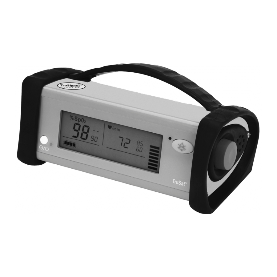
• Details regarding compliance with standards for Medical Electrical Equipment. 1.1 General description The TruSat pulse oximeter is a durable and portable monitor that measures oxygen saturation, pulse rate, and PI r ®, a relative perfusion index. The monitor is powered by an internal battery, which is charged through an external power supply. -
Page 8: Monitor Features
Display area for on-screen control symbols (set pulse beep volume, set alarm volume, switch backlight ON/OFF, display PI r , print) and the lock symbol 10 Battery indicator 11 Power button and external power LED Refer to the TruSat User’s Guide for detailed descriptions of all controls and indicators. 1–2... -
Page 9: Connectors
Sensor connector; defibrillation- DC current proof type BF applied part RS-232 connector for the Trend Manufacturer Download option Power supply connector; external power in Other symbols on the monitor or the screen are described in the TruSat User’s Guide. 1–3... -
Page 10: Safety Precautions
TruSat Technical Reference Manual 1.3 Safety precautions Precautions associated with following safe practices while using the monitor appear throughout this manual. General precautions are listed below. Carefully read all precautions in this manual before repairing or using the monitor. NOTE: For complete information about the safe and appropriate use of a sensor, consult the instructions for that sensor. -
Page 11: Specifications
Product Description and Specifications 1.4 Specifications Specifications are nominal and are subject to change without notice. Factory settings Setting Range Factory setting High SpO alarm limit 51 to 100% or OFF (— —) Low SpO alarm limit 50 to 99% or OFF (— —) High pulse rate alarm limit 30 to 235 bpm or OFF (—... -
Page 12: Monitor
TruSat Technical Reference Manual Pulse rate Measurement and display range: 30 to 250 beats per minute (bpm) Display resolution: 1 bpm First reading, full accuracy: ≤ 15 seconds Accuracy 30 to 250 bpm: ± 2 digits or ± 2%, whichever is greater (without motion) 30 to 250 bpm: ±... -
Page 13: Environmental Conditions
Product Description and Specifications Audio Pulse rate beep: tone rises as oxygen saturation increases and falls as it decreases Adjustable alarm volume and pulse beep volume: 4-segment on-screen controls Volume intensity at distance of 1 m (3.28 ft.): 45 dB minimum to 85 dB maximum External power Power supply (AC to DC converter) AC power input: 100–240 V, 0.5 A, 50–60 Hz... -
Page 14: Compliance
TruSat Technical Reference Manual 1.5 Compliance European Union Medical Device Directive 93/42/EEC: Class IIb EN 60601-1 Medical electrical equipment – Part 1: General requirements for safety (including Amendments 1 and 2) • Type of protection against electric shock: Class I equipment/Internal electrical power source •... -
Page 15: Electromagnetic Compatibility (Emc)
Guidance and manufacturer’s declaration - electromagnetic emissions The TruSat pulse oximeter is suitable for use in the electromagnetic environment specified below. The customer or the user of the monitor should assure that it is used in such an environment. - Page 16 TruSat Technical Reference Manual Guidance and manufacturer’s declaration - electromagnetic immunity The TruSat pulse oximeter is intended for use in the electromagnetic environment specified below. The customer or the user of the monitor should assure that it is used in such an environment.
- Page 17 To assess the electromagnetic environment due to fixed RF trans mitters, an electromagnetic site survey should be considered. If the measured field strength in the location in which the TruSat is used exceeds the applicable RF compliance level above, the TruSat should be observed to verify normal operation. If abnormal performance is observed, additional measures may be necessary, such as re-orienting or relocating the TruSat.
- Page 18 TruSat Technical Reference Manual 1–12...
-
Page 19: Theory Of Operations
2. THEORY OF OPERATIONS This chapter contains: • Functional block diagram. • SpO , pulse rate, and PI r measurement principles. • Functional descriptions of the power supply, System board, Display board, and the Trend Download board (RS-232). 2.1 Functional block diagram Analog Sensor front end... -
Page 20: Measurement Principles
The TruSat pulse oximeter uses the functional calibration method. 2.3 Power supply and battery A Globetek power supply converts power from an AC power source (100 to 240 V, 0.5 A, 50-60 Hz) and outputs power to the monitor (+12 VDC, 1.25 A, 15 watts). -
Page 21: System Board
Theory of Operations 2.4 System board Line power Battery power Supply voltage +12 VDC +4.8 VDC Speaker 4 to 8 ohm Oximetry sensor • LED System board ComWheel • Photodetector • Sensor ID Trend Download board • RS-232 • SPI bus •... -
Page 22: Microcontroller
TruSat Technical Reference Manual Microcontroller The System board microcontroller is responsible for system monitoring, user interface processing, speaker control, display control, alarm LED control, RS-232 communications, SPI bus control, enabling oximetry hardware, and real-time clock control. The microcontroller is supplied by a +3 VDC signal, V_ON, which is always on when power is applied to the board. -
Page 23: Trend Download Board (Rs-232)
Theory of Operations 2.6 Trend Download board (RS-232) Transformer driver Transformer +5 V regulator Board ID High speed Opto-isolation RS-232 driver Low speed Opto-isolation Alarm event relay Trend flash Figure 2-4. Trend Download board block diagram The Trend Download board provides an interface for connecting a personal computer or printer to the monitor. -
Page 24: Alarm Event Relay
TruSat Technical Reference Manual Alarm event relay The alarm event circuit contains a normally-open relay switch that closes in the event of an alarm condition and remains closed until the alarm condition ends. When S1 is switched to “enable,” a multiple-component circuit responds to an incoming signal, energizes the relay coil, and closes the contact between pin 1 and pin 3 of the RS-232 DIN 6 connector (X2). -
Page 25: Troubleshooting
3. TROUBLESHOOTING This chapter contains: • A guide for troubleshooting problem situations. • Board drawings, test points, and connector pin assignments. 3.1 Troubleshooting guide The following chart lists situations that may occur while using the monitor. Follow the recommended action in the order listed until the cause is isolated and corrected. NOTE: Procedures for replacing monitor parts are in the Service Procedures chapter. - Page 26 TruSat Technical Reference Manual Situation Cause Action Green LED remains Display board malfunction. Replace the Display board. ON when monitor is disconnected from external power. System board failure. Replace the System board. Display is blank. Software or hardware Press the Alarm Silence button once to cancel the Continuous tone may malfunction.
-
Page 27: Error Numbers
System board malfunction. Replace the System board. No communication Incorrect cable used to connect PC—use only the TruSat/PC RS-232 cable supplied through RS-232 port. PC or printer to monitor. with the Trend Download option. Printer—use only the TruSat/serial printer cable supplied with the printer. -
Page 28: System Board Components
TruSat Technical Reference Manual 3.2 System board components Figure 3-1. System board—front Figure 3-2. System board—back Digital signal processor (DSP) Complex programmable logic device (CPLD) Microcontroller Test point Test point Test point Transformer Jumper set, board configuration identification, 4 pin... -
Page 29: System Board Test Points
Troubleshooting System board test points Test point Signal name Description Non-isolated/chassis ground GNDF Isolated ground Non-isolated/chassis ground System board connectors ID connector (X1) Pin # Signal Name Description Alternate board A jumper across these two pins will identify a configuration B different board configuration Alternate board A jumper across these two pins will identify a... -
Page 30: Pulse Oximetry Connector (X5)
TruSat Technical Reference Manual Pulse oximetry connector (X5) Pin # Signal Name Description PD_C Photodiode cathode signal Isolated ground IR LED anode, bi-directional current Red LED anode, bi-directional current CATHODES LED cathodes, bi-directional current PD_A Photodiode anode signal Isolated ground... -
Page 31: Trend Download Board Connector (X8)
Troubleshooting Trend Download board connector (X8) Pin # Signal Name Description +3 V power signal, isolated by ferrite +3 V power signal, isolated by ferrite OPT_BRD_ID Trend Download board ID, analog signal SPI_UP_DOUT_BUFF SPI data-out signal, isolated by buffer Non-isolated ground SPI_UP_DIN_BUFF SPI data-in signal, isolated by buffer Non-isolated ground... -
Page 32: Display Board Connector (X12)
TruSat Technical Reference Manual Display board connector (X12) Pin # Signal Name Description V_ON +3 V regulated voltage from DC line Non-isolated ground BACKLIGHT_CUR Backlight supply current BACKLIGHT_CUR Backlight supply current BACKLIGHT_RET_CUR Backlight return current BACKLIGHT_RET_CUR Backlight return current BATT+... -
Page 33: Display Board Components
Troubleshooting 3.3 Display board components Figure 3-3. Display board—front TP13 TP12 TP17 TP16 TP14 TP15 TP18 TP11 TP10 Figure 3-4. Display board—back D3 LCD H1 LED, external power, green H2 LED, alarm, bicolor, red/yellow S1 Power button switch S2 Alarm Silence button switch X1 Connector, board-to-board, 30 pin X2 Backlight Display board test points... -
Page 34: Display Board Connector
TruSat Technical Reference Manual Display board connector System board connector (X1) Pin # Signal Name Description V_ON +3 V regulated voltage from DC line Non-isolated ground BACKLIGHT_CUR Backlight supply current BACKLIGHT_CUR Backlight supply current BACKLIGHT_RET_CUR Backlight return current BACKLIGHT_RET_CUR Backlight return current... -
Page 35: Trend Download Board (Rs-232) Components
Troubleshooting 3.4 Trend Download board (RS-232) components Enable Disable Side View Figure 3-5. Trend Download board F2 Fuse block and fuse for alarm relay switch S1 Alarm relay enable/disable switch X1 Connector, Trend Download board to System board, 20 pin X2 Connector, RS-232 Din 6 X3 Jumper set, board configuration identification, 4 pin Trend Download board connectors... -
Page 36: Id Connector (X3)
TruSat Technical Reference Manual RS-232 connector (X2) Pin # Signal Name Description ALARM_EVENT Alarm event output Transmit data GND connection Ready to send (RTS) Clear to send (CTS) Receive data ID connector (X3) Pin # Signal Name Description Alternate board... -
Page 37: Service Procedures
4. SERVICE PROCEDURES This chapter contains procedures for the following: • Checking the operation of the monitor. • General maintenance. • Installing upgrades, including software and the Trend Download option. • Alarm annunciation setup for monitors with the Trend Download option. •... -
Page 38: Changing The Line Power Filter
TruSat Technical Reference Manual Choose a sensor designed for use on a finger, place it on your finger, and connect it to the monitor. Power ON. NOTE: All pleth bar segments pulsate until the measured values are displayed. When the SpO and pulse rate values are displayed, verify that the lowest pleth bar segment remains visible while one or more of the other segments pulsate. -
Page 39: Setting The Clock
Record the results for comparison with future leakage current tests. Ground resistance test A case ground resistance test is not necessary or appropriate because the TruSat is a SELV (Safety Extra Low Voltage) device as defined in EN 60601-1, Clause 2.4.2. The monitor is powered by an external DC SELV (12 V) power supply. -
Page 40: Planned Maintenance
TruSat Technical Reference Manual 4.2 Planned Maintenance Preventive maintenance and/or calibration are not required for the TruSat pulse oximeter. Battery To extend the life of the battery: • Fully charge the battery once a month. NOTE: After all four battery segments are shaded, wait at least 20 minutes before you disconnect the monitor from the external power source. -
Page 41: Software Upgrade
Service Procedures 4.3 Software upgrade The software upgrade kit includes an upgrade card that contains current versions of the oximetry, system, and other monitor software. You upgrade the software by inserting this card into a connector located on the System board. Checking the current software versions Power ON the monitor. -
Page 42: Trend Download Upgrade
TruSat Technical Reference Manual Note the orientation of the ComWheel encoder cable and the speaker cable. Each is “keyed” for correct connection to the System board. Carefully disconnect both cables from the System board and remove the bumper assembly. Locate the software upgrade connector on the System board. It is circled in Figure 4-2. -
Page 43: Installing The Trend Download Board
Service Procedures Installing the Trend Download board WARNING: Power OFF and disconnect the monitor from external power before performing any procedure that involves disassembly of the monitor. WARNING: Internal electronic components are susceptible to damage by electrostatic discharge. To avoid damage when disassembling the monitor, observe the standard precautions and procedures for handling static- sensitive components. -
Page 44: Alarm Annunciation
TruSat Technical Reference Manual 4.5 Alarm annunciation The TruSat Trend Download board (RS-232) is equipped with an alarm annunciation capability for use with your existing “nurse call” system. If the Trend Download board is installed in your monitor, you must do the following to use this feature: •... -
Page 45: Enabling Alarm Annunciation
Service Procedures Enabling alarm annunciation To conserve battery power, DISABLED is the default setting for the alarm event switch on the Trend Download board. Change the switch setting to ENABLED only if you have customized a cable and intend to connect the monitor to your local “nurse call” system. •... -
Page 46: After Installing The Trend Download Board
TruSat Technical Reference Manual After installing the Trend Download board WARNING: Power OFF and disconnect the monitor from external power before performing any procedure that involves disassembly of the monitor. WARNING: Internal electronic components are susceptible to damage by electrostatic discharge. To avoid damage when disassembling the monitor, observe the standard precautions and procedures for handling static- sensitive components. -
Page 47: Relay Switch Fuse Replacement
Service Procedures Relay switch fuse replacement If overload from the “nurse call” system blows the relay switch fuse on the Trend Download board, replace the fuse with a fuse of the same type and rating. WARNING: Power OFF and disconnect the monitor from external power before performing any procedure that involves disassembly of the monitor. -
Page 48: Repair Procedures
Then go to the assembly instructions to complete the procedure. Refer to the assembly drawing as you disassemble the monitor. See TruSat assembly drawing later in this manual. Right (ComWheel) side disassembly... -
Page 49: Housing Disassembly
Press down on the handle so that it extends out the left side of the housing. Gently lift the tabs away from the housing to release the handle. Monitor assembly Refer to the assembly drawing as you assemble the monitor. See TruSat assembly drawing later in this manual. Housing assembly Position the right end of the handle in the slots in the right side of the housing. -
Page 50: Left Side Assembly
TruSat Technical Reference Manual Install the power button pad at S1 on the Display board by inserting the two guide “posts” through the matching holes on the Display board. 10. Slide the boards all the way into the housing, taking care not to dislodge the Alarm Silence button, the power button, and the power button pad. -
Page 51: Service Parts
This chapter contains: • A list of miscellaneous parts. • A list of the TruSat parts and service kits associated with the assembly drawing of the TruSat. NOTE: Illustrations and connector details for the System board, the Display board, and the Trend Download board (RS-232) are located in the Troubleshooting chapter. -
Page 52: Trusat Assembly
TruSat Technical Reference Manual 5.2 TruSat assembly TruSat parts and service kits The item number identifies the part shown in the assembly drawing. Item Description Plate, end, outer 6050-0006-566 Plate, end, outer, white 6050-0006-584 Bumper, left (not shown) 6050-0006-569 Bumper, left for RS-232 connector... -
Page 53: Trusat Assembly Drawing
Service Parts TruSat assembly drawing 6 places Power supply connector 5–3...