Table of Contents
Advertisement
Advertisement
Table of Contents

Related Manuals for GE AKTA pilot 600


Summary of Contents for GE AKTA pilot 600
- Page 1 ÄKTA ™ pilot 600 User Manual...
-
Page 2: Table Of Contents
Table of Contents Table of Contents Introduction ......................About this manual ..........................Important user information ......................Associated documentation ......................System description ....................Description of the ÄKTA pilot 600 instrument ................Flow path ..............................Accessories .............................. Instrument Configuration software ..................... Description of modules ..................External air sensors (optional) ...................... - Page 3 Table of Contents 5.4.2 Calibrate the conductivity monitor ..................Replacement procedures ........................5.5.1 Replace the pH electrode ......................5.5.2 Replace the Mixer module ......................5.5.3 Replace the UV monitor flow cell .................... 5.5.4 Replace valve fronts ........................Performance tests ....................When to run performance tests ....................
-
Page 4: Introduction
1 Introduction Introduction About this chapter This chapter contains important user information, descriptions of safety notices, intended use of the ÄKTA pilot 600 system, and lists of associated documentation. In this chapter This chapter contains the following sections: Section See page 1.1 About this manual 1.2 Important user information 1.3 Associated documentation... -
Page 5: About This Manual
1 Introduction 1.1 About this manual About this manual Purpose of this manual The User Manual provides you with in-depth instructions and information for using the ÄKTA pilot 600 system. Basic instructions including important safety information are given in the ÄKTA pilot 600 Operating Instructions. Scope of this manual The User Manual covers the ÄKTA pilot 600S (Standard) and ÄKTA pilot 600R (Regulatory) instruments. -
Page 6: Important User Information
1 Introduction 1.2 Important user information Important user information Read the Operating Instructions before using the product All users must read the entire ÄKTA pilot 600 Operating Instructions before installing, operating or maintaining the product. Always keep the Operating Instructions at hand when operating the product. Do not operate the product in any other way than described in the user documentation. - Page 7 1 Introduction 1.2 Important user information Prerequisites In order to follow this manual and use the system in the manner it is intended: ® • The user should have a general understanding of how the computer and Microsoft ® Windows work.
- Page 8 1 Introduction 1.2 Important user information Notes and tips Note: A note is used to indicate information that is important for trouble-free and optimal use of the product. Tip: A tip contains useful information that can improve or optimize your procedures. ÄKTA pilot 600 User Manual 29274559 AA...
-
Page 9: Associated Documentation
Associated documentation Introduction This section describes the user documentation that is delivered with the product, and how to find related literature that can be downloaded or ordered from GE. User documentation for ÄKTA pilot 600 The user documentation listed in the table below is available in printed or on the web PDF format. - Page 10 Declaration of Conformity for EU and/or other regions. Spare Part List List of spare parts available from GE. UNICORN documentation The UNICORN documentation is listed in the following table. The documents are available in the UNICORN Online Help and Documentation section of the on-line help (see...
- Page 11 1 Introduction 1.3 Associated documentation Documentation Main contents UNICORN Method Manual Overview and detailed descriptions of the • method creation features in UNICORN. Workflow descriptions for common operations. • UNICORN Administration and Overview and detailed description of network • Technical Manual setup and complete software installation.
- Page 12 1 Introduction 1.3 Associated documentation Important information In some contexts, important and supplementary information about settings is presented in tooltips, marked by the information symbol Hover over the symbol to show the tooltip. ÄKTA pilot 600 User Manual 29274559 AA...
- Page 13 1 Introduction 1.3 Associated documentation Help for specific instructions To access help for specific instructions in System settings and Manual instructions and for text instructions in the Method Editor module, select the instruction and press F1. Navigation among help topics is not supported from help displayed in this way. User documentation and other literature on the web User documentation and other literature related to ÄKTA pilot 600 system may be...
- Page 14 1 Introduction 1.3 Associated documentation Access documentation from mobile units Scan the code using your mobile phone or tablet computer to access the product page for ÄKTA pilot 600. Select documents to download under RELATED DOCUMENTS. ÄKTA pilot 600 User Manual 29274559 AA...
-
Page 15: System Description
2 System description System description About this chapter This chapter gives an overview of the ÄKTA pilot 600 instrument, available accessories, and the Instrument Configuration software. In this chapter This chapter contains the following sections: Section See page 2.1 Description of the ÄKTA pilot 600 instrument 2.2 Flow path 2.3 Accessories 2.4 Instrument Configuration software... -
Page 16: Description Of The Äkta Pilot 600 Instrument
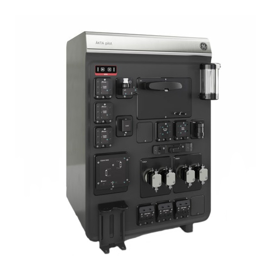
2 System description 2.1 Description of the ÄKTA pilot 600 instrument Description of the ÄKTA pilot 600 instrument Introduction This section gives an overview of the instrument and the available modules. Standard and Regulatory versions of the instrument The ÄKTA pilot 600 instrument is available in two versions: •... - Page 17 2 System description 2.1 Description of the ÄKTA pilot 600 instrument 12 13 Part Description Label Optional (*) Control panel. The instrument version is indicated below the control panel: 600S (red) or 600R (blue) pH monitor Outlet valve 1-3, port 1 can be used for waste Outlet Valve W/1 2 3 Outlet valve 4-6...
- Page 18 2 System description 2.1 Description of the ÄKTA pilot 600 instrument Part Description Label Optional (*) Column valve, including pre- and post-column pressure Column Valve sensor Bottles for pump rinsing solution Inlet valve A1-A3 Inlet Valve A1 A2 A3 Inlet valve A4-A6 Inlet Valve A4 A5 A6 Inlet valve B1-B3...
-
Page 19: Flow Path
2 System description 2.2 Flow path Flow path Introduction This section gives a generalized overview of the flow path in the ÄKTA pilot 600 instrument. The flow path in a specific instrument is determined by the modules that are installed and by the current settings in UNICORN software. - Page 20 2 System description 2.2 Flow path Part Function Air trap valve including air sensor In-line filter (optional) Pre-column Conductivity monitor with temperature sensor (optional) Column valve including pre-column and post-column pressure sensors Conductivity monitor with temperature sensor UV monitor pH module (optional) Outlet valve with 3 ports.
-
Page 21: Accessories
2 System description 2.3 Accessories Accessories Introduction This section gives an overview of the accessories supplied with the system and required for regular maintenance. Accessories included with the ÄKTA pilot 600 instrument Up-to-date information on accessories supplied with the ÄKTA pilot 600 instrument may be obtained from the ÄKTA pilot 600 product pages on www.gelifesciences.com/akta. - Page 22 2 System description 2.3 Accessories Using the Tube bender The Tube bender, provided as an accessory with the instrument, helps in bending tubing without introducing kinks. Short lengths of tubing, especially the i.d. 4.8 mm tubing on the inlet side of the pumps, are particularly susceptible to kinking. Use the Tube bender as described in the steps below.
- Page 23 2 System description 2.3 Accessories Part Description Retaining screw for the module UniNet-9 cable: connect to a free UniNet-9 connector at the back of the instrument Bracket for hanging the Extension box on the Extension stand Note: If the Extension box is used with ÄKTA pilot 600R, the documentation for the instrument will be invalid.
- Page 24 2 System description 2.3 Accessories Extension stand for columns and accessories The Extension stand can be used to mount columns, the Extension box, and the I/O-box. The stand includes holders to organize the tubing. The following illustration shows the Extension stand with a HiScale column attached. ÄKTA pilot 600 User Manual 29274559 AA...
- Page 25 2 System description 2.3 Accessories Module front panel with rails A module front panel with rails is available for attaching ÄKTA accessory holders to the instrument front, for holding accessories such as Superloop™ 150 SNAP. The front panel with rails occupies one module position. Luer-SNAP 3.2 connectors Some maintenance procedures require injection of liquid into a module from a syringe.
- Page 26 2 System description 2.3 Accessories Step Action Connect one end of the tubing to a 5/16" Male - SNAP 3.2 mm union (part no. 29274572, included with accessories). Connect the 5/16" Male union to a Luer - 5/16" Female union (part no. 11002707, ordered separately).
-
Page 27: Instrument Configuration Software
Introduction UNICORN is a common software platform that is used for a range of different products from GE. The platform functionality is adapted to specific systems by installation of the Instrument Configuration software provided with the system. This section gives a brief overview of the function and management of the Instrument Configuration software. - Page 28 2 System description 2.4 Instrument Configuration software NOTICE It is important that the correct Instrument Configuration for the system is downloaded and installed. The system will be unusable if an incorrect Instrument Configuration is installed. ÄKTA pilot 600 User Manual 29274559 AA...
-
Page 29: Description Of Modules
3 Description of modules Description of modules About this chapter This chapter gives additional information about the modules that are presented in ÄKTA pilot 600 Operating Instructions. Technical details can be found in ÄKTA pilot 600S Product Documentation, information about documentation for the R system can be found in ÄKTA pilot 600 Operating Instructions, and installation instructions can be found in respective module installation instruction. -
Page 30: External Air Sensors (Optional)
3 Description of modules 3.1 External air sensors (optional) External air sensors (optional) Introduction This section describes the external air sensors that can be installed on the inlet tubing to detect incoming air if, for example, a buffer or sample container has run out of liquid. Illustration The illustration below shows an external air sensor. - Page 31 3 Description of modules 3.1 External air sensors (optional) • To apply all sample feed onto the column, use a short piece of tubing between the external air sensor and the inlet valve. Remember to have the air trap in-line while applying sample using short tubing and high flow rates, because air might pass be- yond the inlet valve.
- Page 32 3 Description of modules 3.1 External air sensors (optional) Any selections in a method run, for example in the method settings, overrides the selec- tions made in system settings. ÄKTA pilot 600 User Manual 29274559 AA...
-
Page 33: Inlet Valves
3 Description of modules 3.2 Inlet valves Inlet valves Introduction This section describes the inlet valves that are used to select samples and buffers, for pump A and pump B respectively, during the chromatography run. Illustration The illustration below shows the front of the inlet valve module for pump A. Part Description A1 inlet... - Page 34 3 Description of modules 3.2 Inlet valves Function The inlet valve modules consist of a number of membrane valves. The first A inlet port, A1, is used for buffer solution. A2 and A3 are used for sample or buffer solutions. If more A inlets are required, up to three inlet valve modules can be installed which results in nine A inlets.
-
Page 35: Pumps
3 Description of modules 3.3 Pumps Pumps Introduction This section describes the two high precision system pumps, A and B, that pump buffers and samples through the flow path. Illustration The illustration below shows the front of pump A. Part Description Rinsing solution inlet, from the rinsing solution bottle Inlet, from Inlet Valve module... - Page 36 3 Description of modules 3.3 Pumps Part Description Rinsing solution outlet, to the rinsing solution bottle Outlet, to the flow restrictor Function Each system pump module consists of two pump heads. The individual pump heads are identical but actuated in opposite phase to each other. The two pistons and pump heads work alternately to give a continuous, low pulsation, liquid delivery.
-
Page 37: Flow Restrictor
3 Description of modules 3.4 Flow restrictor Flow restrictor Introduction This section describes the flow restrictor, including the system pressure sensor. The flow restrictor prevents siphoning in the system, improves the flow rate and gradient accuracy at low flow rate, and monitors the overall system pressure. Illustration The illustration below shows the front of the flow restrictor module. - Page 38 3 Description of modules 3.4 Flow restrictor Function The module has two separate restrictors for A and B pumps respectively. The flow path inside this module is designed to use inlets from pump A for sample application. The system pressure sensor is located inside the flow restrictor module. This sensor measures the pressure near the outlet, and UNICORN compares the value with the highest allowed and the lowest allowed system pressure.
-
Page 39: Mixer Valve And Mixer (Optional)
3 Description of modules 3.5 Mixer valve and mixer (optional) Mixer valve and mixer (optional) Introduction This section describes the mixer valve and the dynamic mixer that control the buffer mixing from the two system pumps. Illustration The illustration below shows the front of the mixer valve module (left) and the front of the mixer module (right). - Page 40 3 Description of modules 3.5 Mixer valve and mixer (optional) Function The mixer valve module consists of a number of membrane valves. The mixer valve directs the flow through the mixer, or by-passes the mixer, for example during sample application. The mixer mixes the A and B buffers in a 5 mL mixer chamber to a homogeneous buffer composition.
-
Page 41: Air Trap Valve And Air Trap
3 Description of modules 3.6 Air trap valve and air trap Air trap valve and air trap Introduction This section describes the air trap valve and the air trap. For information on how to fill and empty the air trap, see the ÄKTA pilot 600 Operating Instructions. The purpose of the air trap is to trap air that has been introduced into the flow path. - Page 42 3 Description of modules 3.6 Air trap valve and air trap Part Description Outlet, to the air trap Air trap inlet Inlet funnel Manual vent valve knob Manual vent valve port Air trap outlet Inlet, from the air trap Position of the air sensor Outlet, to the next module Function Air is trapped in the upper part of the air trap if the lower part contains liquid.
- Page 43 3 Description of modules 3.6 Air trap valve and air trap Air sensor alarm The alarm of this air sensor is default disabled. If the alarm is enabled, detected air pauses the pumps. To enable the alarm, select Alarm Air Tap valve air sensor in the System Settings dialog box, select Enabled and click OK, see illustration below.
- Page 44 3 Description of modules 3.6 Air trap valve and air trap Air trap indications in the Process Picture The table below explains the four different states. Symbol Explanation The air trap is by-passed, so air in the flow path is not cap- tured.
-
Page 45: In-Line Filter (Optional)
For installation and replacement of a filter, see the ÄKTA pilot 600 Operating Instructions. Illustration The illustrations below show the two in-line filter options, a stainless steel housing and an ULTA™ Capsule CG filter from GE. Part Description Inlet, stainless steel housing... - Page 46 The ULTA Capsule CG filter is mounted using an ULTA CG filter mounting kit, available from GE. This mounting kit is designed for ULTA Capsule CG filters. The pressure limit for these filters is 0.5 MPa, see the ÄKTA pilot 600 Operating Instructions for how to set system pressure limits.
-
Page 47: Column Valve
3 Description of modules 3.8 Column valve Column valve Introduction This section describes the column valve module. The module is used to connect, control and monitor up to two columns, apply sample to a column using a Superloop, and to use Intelligent packing to automatically pack AxiChrom™... - Page 48 3 Description of modules 3.8 Column valve Part Description Port for column position 1, bottom of column Port for column position 1, top of column Port for column position 2, bottom of column Port for column position 2, top of column Pressure sensor just inside the outlet Outlet, to the next module Function...
- Page 49 3 Description of modules 3.8 Column valve Column valve options See the list in the image above. The Waste 2 option is used, for example, during pump wash and air trap drain. The Bypass 1 and Bypass 2 options represent different flow paths in the valve. When priming and cleaning the system, make sure that Bypass 1 is selected first, followed by Bypass 2.
- Page 50 3 Description of modules 3.8 Column valve The four options for unpacking are used to simplify unpacking of columns. Before using an unpacking option, make sure to read each column instruction. Column pressure monitoring The pre- and post-column pressure sensors are located at the inlet and outlet of the column valve.
-
Page 51: Conductivity Monitor
3 Description of modules 3.9 Conductivity monitor Conductivity monitor Introduction This section describes the conductivity monitor modules: • Pre-column conductivity monitor (optional) • Conductivity monitor (always installed in the system) The purpose of these monitors is to continuously measure the conductivity of samples and buffers in the flow path. - Page 52 3 Description of modules 3.9 Conductivity monitor As variation in temperature influences conductivity readings, the conductivity flow cell is fitted with a temperature sensor that measures the temperature of the eluent. A temperature compensation factor is used to report the conductivity in relation to a set reference temperature.
-
Page 53: 3.10 Uv Monitor
3 Description of modules 3.10 UV monitor 3.10 UV monitor Introduction This section describes the UV monitor module. The UV monitor is used to detect proteins eluted from the column. Illustration The illustration below shows the front of the UV monitor module. Part Description Inlet port... - Page 54 3 Description of modules 3.10 UV monitor Pressure protection The UV monitor is sensitive to high pressure, but normally the pressure is low after the column. To protect sensitive monitors after the column, the post-column pressure has an alarm level of 0.8 MPa. This alarm is independent of other settings. UV cell size The UV flow cell is available in two sizes: •...
-
Page 55: Ph Monitor (Optional)
3 Description of modules 3.11 pH monitor (optional) 3.11 pH monitor (optional) Introduction This section describes the optional pH monitor module. The module is used to continu- ously measure the pH of solutions used in the run. Illustration The illustration below shows the front of the pH monitor module. Part Description Dummy electrode... - Page 56 3 Description of modules 3.11 pH monitor (optional) Function The pH module has two positions for the electrode: one position for measurements, calibration or cleaning in-line, and one for storage of the electrode. A dummy is placed in whichever position the electrode is not using. The module also has a manual injection port that facilitates the pH calibration.
-
Page 57: 3.12 Outlet Valves
3 Description of modules 3.12 Outlet valves 3.12 Outlet valves Introduction This section describes the outlet valves, used for outlet fractionation and waste handling. It is optional to have more than one outlet valve. Illustration The illustration below shows the front of two outlet valve modules, the mandatory module above and the first optional module below. - Page 58 3 Description of modules 3.12 Outlet valves Part Description 5 to 9 Outlets for fractionation Function The outlet valve module contains a number of membrane valves to control the flow path during fractionation. For more information about fractionation, see Section 4.2 Fraction- ation, on page 71.
-
Page 59: Operation
4 Operation Operation About this chapter Basic instructions on how to prepare and perform a run are given in the ÄKTA pilot 600 Operating Instructions. This chapter considers additional topics related to operation of the instrument. In this chapter This chapter contains the following sections: Section See page 4.1 Sample application... -
Page 60: Sample Application
4 Operation 4.1 Sample application Sample application About this section A basic description of how to apply a sample to the column in a ÄKTA pilot 600 system is given in ÄKTA pilot 600 Operating Instructions. This section gives more in-depth infor- mation on sample application techniques. -
Page 61: Background Considerations
4 Operation 4.1 Sample application 4.1.1 Background considerations 4.1.1 Background considerations Chromatography techniques Different chromatography techniques make different demands on sample application, as summarized in the table below. These considerations can influence the choice of sample application technique. More information about chromatography techniques may be found in the Life Science Handbooks, available for download from the Support pages on www.gelifesciences.com. - Page 62 4 Operation 4.1 Sample application 4.1.1 Background considerations Option When? Description Apply sample from Recommended for sam- A Superloop (sold separately) is a Superloop ple volumes in the range manually filled with sample and 10 to 150 mL. connected to one of the two col- umn positions.
-
Page 63: Apply Sample From A System Inlet
4 Operation 4.1 Sample application 4.1.2 Apply sample from a system inlet 4.1.2 Apply sample from a system inlet Introduction Samples may be applied from a system inlet using the system pump A. Up to three Inlet valve A modules are supported, giving up to nine inlets, labeled A1 to A9. Inlet A1 is normally used for buffer: other inlets may be used for sample or different buffers as re- quired. - Page 64 4 Operation 4.1 Sample application 4.1.2 Apply sample from a system inlet Setting Description Inject fixed sample Use this option to apply a precise sample volume. Use the volume following additional settings: Select Prime the sample inlet with to ensure repro- •...
- Page 65 4 Operation 4.1 Sample application 4.1.2 Apply sample from a system inlet Setting Description Inject all sample using Use this option to apply all available sample. Sample appli- ext. air sensor 1 cation will stop when the External air sensor 1 detects air in the sample inlet tubing.
- Page 66 4 Operation 4.1 Sample application 4.1.2 Apply sample from a system inlet Setting Description Interrupt sample appli- If this option is selected, sample application will be inter- cation at UV rupted when the UV signal reaches the specified level. This feature is typically used in adsorption chromatography, to detect sample in the flowthrough.
- Page 67 4 Operation 4.1 Sample application 4.1.2 Apply sample from a system inlet Step Action Insert the end of the sample inlet tubing into the sample container. Tip: If the tubing is filled with buffer, introduce a small air bubble into the sample tubing between the buffer and the sample.
-
Page 68: Apply Sample From A Superloop
4 Operation 4.1 Sample application 4.1.3 Apply sample from a Superloop 4.1.3 Apply sample from a Superloop Introduction Samples may be applied to the column from a Superloop, connected to the column valve directly before the column. Superloop 150 SNAP (capacity 150 mL) is fitted with SNAP connections. - Page 69 4 Operation 4.1 Sample application 4.1.3 Apply sample from a Superloop Step Action Connect the Superloop sample outlet (bottom connection) using SNAP con- nectors to the bottom port for the unused column position on the column valve. The illustration below shows a column mounted as Column 1 and a Superloop mounted as Column 2.
- Page 70 4 Operation 4.1 Sample application 4.1.3 Apply sample from a Superloop Setting Description Loop position Shows the column valve position used by the Superloop. This setting can only be changed by changing the Column position in Method Settings. Empty loop with The specified volume will be pumped through the Superloop on to the column.
-
Page 71: Fractionation
4 Operation 4.2 Fractionation Fractionation Introduction Fractionation in ÄKTA pilot 600 system is performed using the outlet valves. Up to five outlet valves can be installed in the system, giving up to 15 outlets. Outlet 1-Waste is used by default as a waste outlet. Fractionation is set in the Phase Properties of the UNICORN method, and can be used in the following phases: •... - Page 72 4 Operation 4.2 Fractionation The remaining settings apply to Outlet valve fractionation: Setting Description Fractionation type Choose the fractionation type. See below for details. Fractionation Choose the outlet position for the first fraction. Subsequent start position fractions will be directed to the next outlet position in numerical order.
- Page 73 4 Operation 4.2 Fractionation Fractionation Description type Fixed outlet Outflow will be directed to the specified outlet position until fractionation ends. Note: Make sure that Stop fractionation at the end of this phase is checked in the current or a subsequent phase as appropriate, to avoid directing all subsequent outflow to the specified outlet position.
- Page 74 4 Operation 4.2 Fractionation Set the parameters as follows: Fractionation Description type Signal Choose the signal to be used for peak detection. Mode Choose the detection mode: Level refers to the magnitude of the signal. • Slope refers to the value of the signal slope of the signal. •...
- Page 75 4 Operation 4.2 Fractionation Conditional fractionation The Conditional Fractionation phase sets conditions for fractionation start and stop that will apply in subsequent phase(s). The conditions will apply until fractionation is stopped, either because the Stop Condition is met or the Stop fractionation at the end of this phase is checked in a subsequent phase.
- Page 76 4 Operation 4.2 Fractionation Fractionation in practice When fractionation is complete or if you re-use outlet positions, empty the outlet tubing by releasing the SNAP connectors on the outlets and allowing the tubing contents to drain into the fraction containers. For unattended fractionation, the maximum number of fractions that can be collected is 14 (using five installed outlet valves).
-
Page 77: Intelligent Packing
4 Operation 4.3 Intelligent packing Intelligent packing Introduction The ÄKTA pilot 600 system can pack AxiChrom columns with a pre-defined Intelligent Packing method that uses the IP port. When column hardware, bed support, resin and target bed height has been entered in the method, default values will automatically be set in the method to provide a complete method. - Page 78 4 Operation 4.3 Intelligent packing Step Action In the New Method dialog box, select Intelligent Packing from the Predefined Method list. Click OK. Result: A new method based on the predefined Intelligent Packing method is created and opened. Verify the method settings. Make sure that Column position and Default curve to show are correct.
- Page 79 Result: Default values are automatically set to provide a complete method. Select GE verified packing settings to get a packing method for GE resins verified by GE. If you use a custom resin, the only option is Custom packing settings.
- Page 80 4 Operation 4.3 Intelligent packing Perform the packing Follow the steps below to perform the packing. Use the UNICORN method created above. Step Action Connect position 1 or 2 according to the method on the Column valve module to the top (on the adaptor) and bottom of the AxiChrom column. Connect the IP port to the horizontal nipple on the column top (not on the adaptor).
-
Page 81: Dual Pump Flow
4 Operation 4.4 Dual pump flow Dual pump flow Introduction It is possible to use both pumps to obtain a flow rate in the range 600 to 1200 mL/min. This function is called Dual pump flow. Isocratic applications When Dual pump flow is used during isocratic applications, the flow rate can be set to up to 1200 mL/min. - Page 82 4 Operation 4.4 Dual pump flow Using the Process Picture Follow the steps below to start dual pump flow using the Process Picture. Step Action Click on one of the pumps to open the System pumps dialog box. Tick the Dual pump flow check box, enter System flow value and click Set. Using dual pump flow manually Follow the steps below to start dual pump flow using manual instructions.
- Page 83 4 Operation 4.4 Dual pump flow Using dual pump flow in a method Follow the steps below to use dual pump flow in a UNICORN method. These steps must be performed for each phase that uses dual pump flow. Step Action Open the Text Instructions tab for the phase.
-
Page 84: Pressure Control
4 Operation 4.5 Pressure control Pressure control Introduction Pressure control is an optional feature that may be used to regulate the flow rate in order to avoid the risk of method stop due to pressure alarms. If the pressure approaches the limit, for example if the sample has higher viscosity than the buffer, the flow rate is au- tomatically lowered. - Page 85 4 Operation 4.5 Pressure control Optimize pressure control settings To optimize pressure control parameters, change the settings manually and test the new settings with a manual run. Follow the steps below: Step Action Open the Advanced:Pressure control parameters section of Manual instruc- tions in System Control.
- Page 86 4 Operation 4.5 Pressure control Step Action Open Pressure control parameters in the Advanced section of the System Settings dialog. Set the parameters as required. Click or press F1 to access the UNICORN online help for the pressure control parameters. Click OK.
-
Page 87: Performing Runs In A Cold Environment
4 Operation 4.6 Performing runs in a cold environment Performing runs in a cold environment Introduction The instrument can be placed and run in a cold cabinet or room. When running the in- strument in a cold environment, take the precautions listed in this section. Precautions concerning runs in a cold cabinet NOTICE... - Page 88 4 Operation 4.6 Performing runs in a cold environment Use equilibrated solutions Always use solutions equilibrated to the ambient temperature, for example, sample so- lutions, buffers, and standard buffers for pH calibration. Temperature differences might for example increase outgassing. Higher viscosity Generally, cold solutions have higher viscosity than warm solutions.
-
Page 89: Maintenance
5 Maintenance Maintenance About this chapter Regular maintenance of the ÄKTA pilot 600 system is essential for reliable function. This chapter describes the recommended maintenance schedules and provides detailed instructions for maintenance operations. In this chapter This chapter contains the following sections: Section See page 5.1 Maintenance manager... - Page 90 WARNING Use only approved parts. Only spare parts and accessories that are approved or supplied by GE may be used for maintaining or servicing the product. WARNING For continued protection against injury risks due to fluid jets, burst pipes or potentially explosive atmosphere, the user must test the piping system for leakage at maximum operating pressure.
- Page 91 5 Maintenance NOTICE Remove all columns from the instrument before performing main- tenance. NOTICE Do not allow solutions which contain dissolved salts, proteins or other solid solutes to dry out in the UV flow cell. ÄKTA pilot 600 User Manual 29274559 AA...
-
Page 92: Maintenance Manager
5 Maintenance 5.1 Maintenance manager Maintenance manager Introduction The Maintenance Manager in UNICORN software displays general information and op- erational statistics for the ÄKTA pilot 600 system and modules. It also allows creation of automated notifications for maintenance actions, based on calendar time and operational statistics. -
Page 93: Maintenance Schedule
5 Maintenance 5.2 Maintenance schedule Maintenance schedule Introduction Maintenance procedures to be performed by the user are outlined below. Periodic maintenance The following periodic maintenance should be performed by the user of the ÄKTA pilot 600 system. Interval Maintenance action Instructions Daily or before each Calibrate the pH monitor. - Page 94 5 Maintenance 5.2 Maintenance schedule Maintenance action Instructions Run System CIP (System cleaning-in-place) See the ÄKTA pilot 600 Operating Instructions Sanitize the instrument See the ÄKTA pilot 600 Operating Instructions Clean and store the pH electrode See the ÄKTA pilot 600 Operating Instructions Clean the conductivity flow cell Section 5.3.1 Clean the conduc-...
-
Page 95: Cleaning Procedures
5 Maintenance 5.3 Cleaning procedures Cleaning procedures About this section This section describes procedures for cleaning the ÄKTA pilot 600 instrument and com- ponents. See the ÄKTA pilot 600 Operating Instructions for additional cleaning instructions. Note: For column cleaning and storage procedures, refer to the column instructions. Refer to the computer documentation for recommendations for cleaning the computer equipment. -
Page 96: Clean The Conductivity Flow Cell
5 Maintenance 5.3 Cleaning procedures 5.3.1 Clean the conductivity flow cell 5.3.1 Clean the conductivity flow cell Maintenance interval Clean the conductivity flow cell when the signal is unstable or when unexpected readings are obtained. Required material The following materials are required: •... - Page 97 5 Maintenance 5.3 Cleaning procedures 5.3.1 Clean the conductivity flow cell Step Action Disconnect the tubing from the top of the conductivity monitor and replace it with a piece of tubing leading to the waste container. Flush the conductivity flow cell with 25 to 30 mL distilled water, using a sy- ringe attached to the Luer-to-SNAP connector.
-
Page 98: Clean The Uv Flow Cell
5 Maintenance 5.3 Cleaning procedures 5.3.2 Clean the UV flow cell 5.3.2 Clean the UV flow cell Maintenance interval Clean the UV flow cell every six months, or when required. NOTICE Keep UV flow cell clean. Do not allow solutions containing dissolved salts, proteins or other solid solutes to dry out in the flow cell. - Page 99 5 Maintenance 5.3 Cleaning procedures 5.3.2 Clean the UV flow cell Step Action Disconnect the tubing from the top of the UV monitor and replace it with a piece of tubing leading to the waste container. Flush the flow cell with 25 to 30 mL distilled water, using a syringe attached to the Luer-to-SNAP connector.
-
Page 100: Calibration Procedures
5 Maintenance 5.4 Calibration procedures Calibration procedures About this section This section provides instructions for calibration procedures that can be performed using the System Control module in UNICORN software. In this section This section contains the following subsections. Section See page 5.4.1 Reset the pressure sensors 5.4.2 Calibrate the conductivity monitor ÄKTA pilot 600 User Manual 29274559 AA... -
Page 101: Reset The Pressure Sensors
5 Maintenance 5.4 Calibration procedures 5.4.1 Reset the pressure sensors 5.4.1 Reset the pressure sensors Introduction The ÄKTA pilot 600 system is fitted with three pressure sensors, for monitoring system pressure, pre-column pressure and post-column pressure. The pressure sensors should be reset at intervals by setting the reading for atmospheric pressure to zero in UNICORN software. - Page 102 5 Maintenance 5.4 Calibration procedures 5.4.1 Reset the pressure sensors Monitored pres- Placing Disconnect tubing sure Pre-column (PreC) At the inlet to the column Column valve inlet pressure valve Post-column At the outlet from the column Column valve outlet (PostC) pressure valve Reset the pressure sensors Follow the steps below to reset the pressure sensors.
- Page 103 5 Maintenance 5.4 Calibration procedures 5.4.1 Reset the pressure sensors Step Action In the Calibration dialog, choose the pressure sensor in the Monitor to calibrate list. If the Current value is outside the range ± 0.02 MPa (0.2 bar, 2.9 psi), click Reset pressure.
-
Page 104: Calibrate The Conductivity Monitor
5 Maintenance 5.4 Calibration procedures 5.4.2 Calibrate the conductivity monitor 5.4.2 Calibrate the conductivity monitor Introduction Two types of calibration can be performed: • Conductivity monitor - user calibration: Calibrates the conductivity cell constant. • Conductivity monitor - factory calibration: Restores the conductivity cell constant to the factory default value. - Page 105 5 Maintenance 5.4 Calibration procedures 5.4.2 Calibrate the conductivity monitor Step Action Clean the conductivity flow cell before calibration (see Section 5.3.1 Clean the conductivity flow cell, on page 96). Disconnect the tubing from the bottom of the conductivity monitor and re- place it with a Luer-to-SNAP connector.
- Page 106 5 Maintenance 5.4 Calibration procedures 5.4.2 Calibrate the conductivity monitor Step Action In the Calibration dialog, choose Conductivity monitor - user calibration in the Monitor to calibrate list. Flush the conductivity flow cell twice with 25 to 30 mL distilled water, using a syringe attached to the Luer-to-SNAP connector.
- Page 107 5 Maintenance 5.4 Calibration procedures 5.4.2 Calibrate the conductivity monitor Step Action Select System:Calibrate from the UNICORN System control menu. In the Calibration dialog, choose Conductivity monitor - factory calibration in the Monitor to calibrate list. Click Restore. Result: The conductivity cell constant is restored to the factory default value. The conductivity cell constant is printed on the packaging of the Conductiv- ity monitor.
- Page 108 5 Maintenance 5.4 Calibration procedures 5.4.2 Calibrate the conductivity monitor Conductivity of 1.00 M NaCl at 20–30°C Temperature (°C) ÄKTA pilot 600 User Manual 29274559 AA...
-
Page 109: Replacement Procedures
5 Maintenance 5.5 Replacement procedures Replacement procedures About this section This section gives instructions for the replacement procedures to be performed by the user of ÄKTA pilot 600 instrument. In this section This section contains the following subsections: Section See page 5.5.1 Replace the pH electrode 5.5.2 Replace the Mixer module 5.5.3 Replace the UV monitor flow cell... - Page 110 5 Maintenance 5.5 Replacement procedures WARNING Hazardous chemicals. Always empty the system of liquids before service. WARNING Decontaminate before maintenance. To avoid exposing personnel to potentially hazardous substances, clean and sanitize the ÄKTA pilot 600 system before maintenance or service. ÄKTA pilot 600 User Manual 29274559 AA...
-
Page 111: Replace The Ph Electrode
5 Maintenance 5.5 Replacement procedures 5.5.1 Replace the pH electrode 5.5.1 Replace the pH electrode Maintenance interval Replace the pH electrode every six months, or when required. Required material The following materials are required: • pH electrode • distilled water •... -
Page 112: Replace The Mixer Module
Replace the Mixer module when the existing module malfunctions. Required material The following is required: • Mixer module (available as a spare part from GE) • 7 mm socket tool Procedure Follow the steps below to replace the Mixer module. - Page 113 5 Maintenance 5.5 Replacement procedures 5.5.2 Replace the Mixer module Step Action Reconnect the tubing to the mixer chamber. Flush the system with water or buffer to remove the air from the new module. ÄKTA pilot 600 User Manual 29274559 AA...
-
Page 114: Replace The Uv Monitor Flow Cell
5 Maintenance 5.5 Replacement procedures 5.5.3 Replace the UV monitor flow cell 5.5.3 Replace the UV monitor flow cell Introduction The UV monitor may need replacement in two situations: • Changing between 2 mm and 5 mm path length flow cells •... - Page 115 5 Maintenance 5.5 Replacement procedures 5.5.3 Replace the UV monitor flow cell Step Action Push the latch on the UV detector to disconnect the detector. Note: The UV lamp does not operate while the UV detector is disconnected. Pull off the detector with the flow cell off the instrument. Note: Make sure that the flow cell does not come into contact with any liquid, and that no liquid enters the UV detector or the front panel.
- Page 116 5 Maintenance 5.5 Replacement procedures 5.5.3 Replace the UV monitor flow cell Step Action Remove the flow cell from the detector. Do not touch the exposed optical fiber connectors. Note: If you do accidentally touch the optical fiber connectors, clean them according Clean the optical fiber connectors, on page 116.
- Page 117 5 Maintenance 5.5 Replacement procedures 5.5.3 Replace the UV monitor flow cell WARNING Hazardous substances. When using hazardous chemicals, take all suitable protective measures, such as wearing protective clothing, glasses and gloves resistant to the substances used. Fol- low local and/or national regulations for safe operation and maintenance of the product.
-
Page 118: Replace Valve Fronts
The valve fronts only need replacing if they are damaged. Procedure Obtain a new valve front from GE, then follow the procedure for replacing valve mem- branes (described in the ÄKTA pilot 600 Operating Instructions). ÄKTA pilot 600 User Manual 29274559 AA... -
Page 119: Performance Tests
6 Performance tests Performance tests About this chapter Performance tests allow the user to test the integrity and functional aspects of the whole ÄKTA pilot 600 system or of individual components. This chapter describes in general terms how to access, run, and assess performance tests. -
Page 120: When To Run Performance Tests
6 Performance tests 6.1 When to run performance tests When to run performance tests Schedule Performance tests may be run at any time, as required. Recommendations are given in the following table. Occasion Test After system installation Run the system tests in the following order 1 System leakage test 2 System backpressure test 3 System test... - Page 121 6 Performance tests 6.1 When to run performance tests Performance test run order Under certain conditions, some performance tests should be run in a specific order ac- cording to the table below. In other circumstances (for example, when membranes are changed on a specific valve), tests may be run independently of each other.
-
Page 122: How To Run Performance Tests
6 Performance tests 6.2 How to run performance tests How to run performance tests Introduction This section describes the general procedure for running performance tests. Details of the individual tests including purpose and required materials are given in the method notes for each test method. - Page 123 6 Performance tests 6.2 How to run performance tests Step Action Select Performance Test and Report... from the System menu. Select the test you want to run. Method notes for the selected test are shown in the right-hand panel. Note: This dialog lists tests for all modules that can be installed in the ÄKTA pilot 600 system.
- Page 124 6 Performance tests 6.2 How to run performance tests Step Action Select whether the test report should be saved to a file and/or printed. Note: Sending the report to a printer requires that a system printer is installed on the UNICORN Instrument Server (see the UNICORN Administration and Tech- nical Manual for details).
- Page 125 6 Performance tests 6.2 How to run performance tests Reference capillaries are provided with the system, and may also be obtained separately from GE. ÄKTA pilot 600 User Manual 29274559 AA...
-
Page 126: How To Evaluate Performance Tests
6 Performance tests 6.3 How to evaluate performance tests How to evaluate performance tests Introduction This section describes how to evaluate the outcome of performance tests. Inspect for leaks Valve module tests and other leakage tests expose the system to pressures close to the system pressure limit by running the system pumps at a low flow rate with the flow path closed at some point. - Page 127 6 Performance tests 6.3 How to evaluate performance tests The reports are saved in the folder C:\Program Files (x86)\GE . Each test generates Healthcare\UNICORN\UNICORN <version number>\Temp a text file with the name of the test as filename. An incremented serial number is added if a file with the same name already exists.
-
Page 128: Troubleshooting
Basic troubleshooting is described in the ÄKTA pilot 600 Operating Instructions. If you have problems that cannot be resolved using the information provided here, contact your GE service organization. In this chapter This chapter contains the following sections:... -
Page 129: System Leakage Test Failure
Correct the problem according to the table below, and rerun the System leakage test to make sure the leakage is corrected. If the problem persists after corrective action has been applied, contact your GE representative. Cause of failure Corrective action Visible leakage at a Make sure that the SNAP connectors are correctly fitted. -
Page 130: System Backpressure Test Failure
The backpressure will drop when the blocked module is excluded from the flow path. If the cause of the failure cannot be located, contact your GE service organization. ÄKTA pilot 600 User Manual 29274559 AA... -
Page 131: System Test Failure
Corrective actions Corrective actions in the case of failure are listed in the table below. If the problem persists after corrective action has been applied, contact your GE representative. Note: It is important that the correct concentrations (1% (v/v) acetone and 1 M NaCl) are used in the System test and that the solutions are thoroughly mixed. - Page 132 7 Troubleshooting 7.3 System test failure Failed test Corrective action Curve amplitude stability Make sure that the temperature compensation is turned (conductivity) on (the temperature compensation factor is not zero). If the test is performed in a cold-room, the temperature compensation factor should be 2.1.
-
Page 133: Other Performance Tests
7 Troubleshooting 7.4 Other performance tests Other performance tests Corrective actions The Instrument Configuration software installed with the system (see Section 2.4 Instru- ment Configuration software, on page 27) provides an extensive set of performance tests for individual modules. The table below gives some guidance concerning corrective ac- tions when individual module tests fail. -
Page 134: Reference Information
8 Reference information Reference information About this chapter System specifications, chemical resistance information and other basic reference infor- mation are given in the ÄKTA pilot 600 Operating Instructions and the ÄKTA pilot 600S Product Documentation for ÄKTA pilot 600S systems. Detailed information specific to the individual system is provided separately with ÄKTA pilot 600R systems. -
Page 135: Component Volumes
8 Reference information 8.1 Component volumes Component volumes Module volumes The table below lists the internal volumes of the modules in ÄKTA pilot 600 system. Module Internal volume (mL) External air sensor Inlet valve Pump (two pump heads) Pump rinse system Flow restrictor Air trap valve Air trap... -
Page 136: Ordering Information
8 Reference information 8.2 Ordering information Ordering information Visit gelifesciences.com Refer to our website www.gelifesciences.com/aktapilot or GE representative for further information about the following topics: • System recommendations • Literature • Service • Training • Accessories • Ordering information Spare parts Your local GE representative can suggest recommended spare parts. -
Page 137: Index
Index Index Accessories Delta column pressure, 50 extension box, 22 Documentation extension stand, 24 on the web, 13 I/O-box, 23 Documentation package included, 21 regulatory version, 10 Module front panel with standard version, 9 rails, 25 Dual pump flow, 81 optional, 22 for isocratic applications, 81 Air sensor... - Page 138 Index Intelligent packing, 77 pH monitor, 55 method, 77 replace the pH elec- Intended use, 6 trode, 111 PI regulation, 84 Pre-column conductivity moni- tor, 52 Leakage test, 129 Pre-column pressure, 50 Liquid flow path, 19 Prerequisites, 7 Luer-to-SNAP connectors, 25 Pressure control, 84 parameters, 85 Pressure monitors...
- Page 139 Index UV flow cell cleaning, 98 Troubleshooting, 128 optical fiber connec- Tubing cutter, 21 tions, 116 Typographical conventions, 5 replacing, 114 UV monitor, 53 clean UV flow cell, 98 ULTA filter, 45 replace UV flow cell, 114 UNICORN software UV test, 133 documentation, 10 online help, 11 User documentation, 9...
- Page 140 All goods and services are sold subject to the terms and conditions of sale of the company within GE Healthcare which supplies them. A copy of these terms and conditions is available on request. Contact your local GE Healthcare repre- sentative for the most current information.