GE akta pure Operating Instructions Manual
Hide thumbs
Also See for akta pure:
- User manual (522 pages) ,
- Operating instructions manual (142 pages)
Table of Contents
Advertisement
Quick Links
Advertisement
Table of Contents

Related Manuals for GE akta pure


Summary of Contents for GE akta pure
- Page 1 ÄKTA ™ pure Operating Instructions Original instructions...
-
Page 2: Table Of Contents
Table of Contents Table of Contents Introduction ......................About this manual ..........................Important user information ......................Regulatory information ........................1.3.1 EU Directives ............................ 1.3.2 Eurasian Customs Union ......................1.3.3 Regulations for USA and Canada ................... 1.3.4 Other regulations and standards .................... Associated documentation ...................... - Page 3 Table of Contents Prepare the system for a run ................Before you prepare the system ...................... Prepare the flow path ......................... Prime inlets and purge pump heads ................... Connect a column ..........................Pressure alarms ............................. Prepare for a run at cold room temperature ................Run a method ......................
-
Page 4: Introduction
1 Introduction Introduction About this chapter This chapter contains important user information, descriptions of safety notices, regula- tory information, intended use of the ÄKTA pure system, and lists of associated documen- tation. In this chapter This chapter contains the following sections: Section See page 1.1 About this manual... -
Page 5: About This Manual
1 Introduction 1.1 About this manual About this manual Purpose of this manual The Operating Instructions provide you with the information needed to install, operate and maintain the product in a safe way. Scope of this manual The Operating Instructions cover ÄKTA pure 25 and ÄKTA pure 150 instruments, using previously created methods in UNICORN software 6.3.2 and later. -
Page 6: Important User Information
1 Introduction 1.2 Important user information Important user information Read this before operating the product All users must read the entire Operating Instructions before installing, operating or maintaining the product. Always keep the Operating Instructions at hand when operating the product. Do not operate the product in any other way than described in the user documentation. - Page 7 1 Introduction 1.2 Important user information Safety notices This user documentation contains safety notices (WARNING, CAUTION, and NOTICE) concerning the safe use of the product. See definitions below. WARNING WARNING indicates a hazardous situation which, if not avoided, could result in death or serious injury. It is important not to proceed until all stated conditions are met and clearly understood.
-
Page 8: Regulatory Information
This section lists the regulations and standards that apply to the ÄKTA pure instrument. Manufacturing information The table below summarizes the required manufacturing information. Requirement Information Name and address of manufacturer GE Healthcare Bio-Sciences AB, Björkgatan 30, SE 751 84 Uppsala, Sweden In this section Section See page 1.3.1 EU Directives 1.3.2 Eurasian Customs Union... -
Page 9: Eu Directives
• used according to the Operating Instructions or user manuals, and • used in the same state as it was delivered from GE, except for alterations described in the Operating Instructions or user manuals. ÄKTA pure Operating Instructions 29022997 AF... -
Page 10: Eurasian Customs Union
Telephone: + 46 771 400 600 Importer and/or company for obtain- GE Healthcare LLC ing information about importer GE Healthcare Life Sciences Presnenskaya nab., 10C, 12th floor RU-123 317 Moscow, Russian Federation Telephone 1: + 7 495 411 9714 Fax nr: + 7 495 739 6932 Email: LSrus@ge.com... -
Page 11: Regulations For Usa And Canada
The user is cautioned that any changes or modifications not expressly approved by GE could void the user’s authority to operate the equipment. This equipment has been tested and found to comply with the limits for a Class A digital device, pursuant to part 15 of the FCC Rules. -
Page 12: Other Regulations And Standards
1 Introduction 1.3 Regulatory information 1.3.4 Other regulations and standards 1.3.4 Other regulations and standards Introduction This section describes the standards that apply to the ÄKTA pure system. Environmental conformity This product conforms to the following environmental requirements. Standards, machinery and electrical equipment Standard requirements fulfilled by this product are summarized in the table below. - Page 13 1 Introduction 1.3 Regulatory information 1.3.4 Other regulations and standards NOTICE This equipment is not intended for use in residential environments and may not provide adequate protection to radio reception in such environments. ÄKTA pure Operating Instructions 29022997 AF...
-
Page 14: Associated Documentation
1 Introduction 1.4 Associated documentation Associated documentation Introduction This section describes the user documentation that is delivered with ÄKTA pure. User documentation The user documentation listed in the table below is available in printed or PDF format. The complete documentation is also available on the User Documentation CD. Document Main contents ÄKTA pure Unpacking Instruction... - Page 15 1 Introduction 1.4 Associated documentation Documentation Main contents Getting started with Video clips showing common workflows in the • Evaluation Evaluation module. Note: Overview of features of the Evaluation module. • Available in UNICORN 7.0 and later. UNICORN Method Manual Overview and detailed descriptions of the method •...
- Page 16 1 Introduction 1.4 Associated documentation Additional literature For practical tips on chromatography, refer to ÄKTA Laboratory-scale: Chromatography Systems Instrument Management Handbook (product code 29010831). ÄKTA pure Operating Instructions 29022997 AF...
-
Page 17: Safety Instructions
2 Safety instructions Safety instructions About this chapter This chapter describes safety precautions, labels and symbols that are attached to the equipment. In addition, the chapter describes emergency and recovery procedures, and provides recycling information. In this chapter This chapter contains the following sections: Section See page 2.1 Safety precautions... -
Page 18: Safety Precautions
2 Safety instructions 2.1 Safety precautions Safety precautions Introduction ÄKTA pure is powered by mains voltage and handles materials that may be hazardous. Before installing, operating or maintaining the system, you must be aware of the hazards described in this manual. Follow the instructions provided to avoid personal injuries or damage to the product, or to other personnel and equipment in the area. - Page 19 2 Safety instructions 2.1 Safety precautions WARNING Do not use any accessories not supplied or recommended by GE. WARNING Do not use ÄKTA pure if it is not working properly, or if it has suffered any damage, for example: •...
- Page 20 2 Safety instructions 2.1 Safety precautions WARNING Hazardous substances and biological agents. When using haz- ardous chemical and biological agents, take all suitable protective measures, such as wearing protective clothing, glasses and gloves resistant to the substances used. Follow local and/or national regulations for safe operation and maintenance of ÄKTA pure.
- Page 21 Supply voltage. Before connecting the power cord, make sure that the supply voltage at the wall outlet corresponds to the marking on the instrument. WARNING Power cord. Only use power cords with approved plugs delivered or approved by GE. ÄKTA pure Operating Instructions 29022997 AF...
- Page 22 2 Safety instructions 2.1 Safety precautions WARNING Access to power switch and power cord with plug. Do not block access to the power switch and power cord. The power switch must always be easy to access. The power cord with plug must always be easy to disconnect.
- Page 23 2 Safety instructions 2.1 Safety precautions NOTICE Any computer used with the equipment must comply with EN/IEC 60950-1, and be installed and used according to the manufacturer's instructions. System operation WARNING Electrical shock hazard after spillage. If there is a risk that large volumes of spilled liquid may penetrate the casing of the instrument, immediately switch off the instrument, disconnect the power cord, and contact an authorized service engineer.
- Page 24 2 Safety instructions 2.1 Safety precautions CAUTION Max. weight on Buffer tray. Do not place containers with a volume of more than 5 liters each on the Buffer tray. The total allowed weight on the Buffer tray is 20 kg. CAUTION Disconnect power.
- Page 25 2 Safety instructions 2.1 Safety precautions NOTICE Keep UV flow cell clean. Do not allow solutions containing dissolved salts, proteins or other solid solutes to dry out in the flow cell. Do not allow particles to enter the flow cell, as damage to the flow cell may occur.
- Page 26 Maintenance WARNING Electrical shock hazard. All repairs should be done by service personnel authorized by GE. Do not open any covers or replace parts unless specifically stated in the user documentation. WARNING Disconnect power. Always disconnect power from the instrument before replacing any component on the instrument, unless stated otherwise in the user documentation.
- Page 27 2 Safety instructions 2.1 Safety precautions CAUTION Cleaning the ÄKTA pure instrument before decommissioning. • Wipe the ÄKTA pure instrument and any modules with a damp tissue using a cleaning agent so that no hazardous solvents or biological agents remain on the surface. •...
-
Page 28: Labels
2 Safety instructions 2.2 Labels Labels Introduction This section describes the system label and other safety or regulatory labels that are attached to the product. ÄKTA pure instrument label The serial number of the ÄKTA pure instrument is printed on the instrument labels, located on the back of the instrument and below the pump tray on the front of the instrument. - Page 29 Warning! Read the Operating Instruction before using the system. Electrical shock hazard. All repairs should be done by service personnel authorized by GE. Do not open any covers or replace parts unless specifically stated in the user documentation. Supply voltage. Before connecting the power cord, make sure that the supply voltage at the wall outlet corresponds to the marking on the instrument.
- Page 30 2 Safety instructions 2.2 Labels Label Meaning The system complies with applicable European directives. The system complies with applicable requirements for Australia and New Zealand. This symbol indicates that ÄKTA pure has been certified by a Nationally Recognized Testing Laboratory (NRTL). This product Conforms to UL 61010-1, and is Certified to CAN/CSA-C22.2 No.
-
Page 31: Emergency Procedures
2 Safety instructions 2.3 Emergency procedures Emergency procedures Introduction This section describes how to perform an emergency shutdown of the ÄKTA pure instru- ment, including connected equipment. This section also describes the results in the event of power failure or network interruption. Emergency shutdown In an emergency situation, stop the run by either pausing the run or switching off the instrument as described below:... - Page 32 2 Safety instructions 2.3 Emergency procedures If you want then... to... switch off the press the Power switch to the 0 position, or • instrument disconnect the power cord from the wall socket. • Result: The run is interrupted immediately. Note: The sample and data may be lost as a result of switching off the power.
- Page 33 2 Safety instructions 2.3 Emergency procedures Power failure to... will result in... Computer The UNICORN computer shuts down • The Power/Communication indicator (white) • on the Instrument control panel displays a slowly flashing light. The run is interrupted immediately • Data generated up to 10 seconds before the •...
- Page 34 2 Safety instructions 2.3 Emergency procedures Step Action If the instrument was switched off, press the Power switch on the instrument. Result: The instrument should start and the Instrument control panel should display a white, slowly flashing light. Turn on the computer and monitor. Start UNICORN and connect to the system.
-
Page 35: Recycling Information
2 Safety instructions 2.4 Recycling information Recycling information Introduction This section contains information about the decommisioning of ÄKTA pure. Decontamination The product must be decontaminated before decommissioning. All local regulations must be followed with regard to scrapping of the equipment. Disposal of the product When taking the product out of service, the different materials must be separated and recycled according to national and local environmental regulations. -
Page 36: Declaration Of Hazardous Substances (Dohs)
2 Safety instructions 2.5 Declaration of Hazardous Substances (DoHS) Declaration of Hazardous Substances (DoHS) 根据SJ/T11364-2014《电子电气产品有害物质限制使用标识要求》特提供如下有关污染控制方面的 信息。 The following product pollution control information is provided according to SJ/T11364-2014 Marking for Restriction of Hazardous Substances caused by electrical and electronic products. 电子信息产品污染控制标志说明 Explanation of Pollution Control Label 该标志表明本产品含有超过中国标准GB/T 26572 《电子电气产品中限用物质的限... - Page 37 2 Safety instructions 2.5 Declaration of Hazardous Substances (DoHS) 有害物质的名称及含量 Name and Concentration of Hazardous Substances 产品中有害物质的名称及含量 Table of Hazardous Substances’ Name and Concentration 部件名称 有害物质 Component name Hazardous substance 铅 汞 镉 六价铬 多溴联苯 多溴二苯醚 (Pb) (Hg) (Cd) (Cr(VI)) (PBB) (PBDE) 29018224...
-
Page 38: System Description
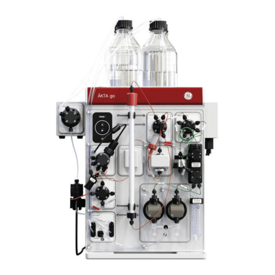
3 System description System description About this chapter This chapter gives an overview of the ÄKTA pure system: instrument, software and ac- cessories. In this chapter This chapter contains the following sections: Section See page 3.1 ÄKTA pure instrument overview 3.2 UNICORN software Illustration of the system The illustration below shows the ÄKTA pure instrument with UNICORN software installed... -
Page 39: Äkta Pure Instrument Overview
3 System description 3.1 ÄKTA pure instrument overview ÄKTA pure instrument overview Introduction This section gives an overview of the ÄKTA pure instrument. Technical details about the instrument and the individual modules are found in ÄKTA pure User Manual. Exterior design ÄKTA pure has a modular design, with all liquid handling modules placed on the exterior of the instrument. - Page 40 3 System description 3.1 ÄKTA pure instrument overview Illustrations of the main parts of the instrument The illustrations below show the location of the main parts of the instrument. Part Function Wet sides Buffer tray Holder rails Instrument control panel Power switch Ventilation panel ÄKTA pure Operating Instructions 29022997 AF...
- Page 41 3 System description 3.1 ÄKTA pure instrument overview Example of a typical configuration of the wet side The descriptions of ÄKTA pure and the work flow in this manual are based on an instru- ment that consists of the modules and parts shown in the illustration below. Part Function Inlet valve...
- Page 42 3 System description 3.1 ÄKTA pure instrument overview Part Function Column valve UV monitor Available modules The modular design allows the user to customize ÄKTA pure in multiple ways. The system is always delivered with the core modules of the selected configuration, but optional modules may be added to the flow path.
- Page 43 3 System description 3.1 ÄKTA pure instrument overview Module Label in ÄKTA pure 25 ÄKTA pure 150 Column valves V9-C V9H-C V9-Cs V9H-Cs pH valve V9-pH V9H-pH Outlet valves V9-O V9H-O V9-Os V9H-Os Versatile valve V9-V V9H-V UV monitors U9-L U9-L U9-M U9-M...
- Page 44 3 System description 3.1 ÄKTA pure instrument overview Core module Description Mixer M9 Mixes the buffers delivered from the system pumps to a homoge- neous buffer composition. Three Mixer chambers are available for ÄKTA pure 25, their volumes are: 0.6 ml, 1.4 ml (mounted at delivery) and 5 ml. Three Mixer chambers are available for ÄKTA pure 150.
- Page 45 3 System description 3.1 ÄKTA pure instrument overview Option Module Description Column valve Column valve V9-C or Connects up to five columns to the instru- V9H-C ment, and directs the flow onto one col- umn at a time. Column valve V9-Cs Connects one column to the instrument.
- Page 46 3 System description 3.1 ÄKTA pure instrument overview Illustration of the Instrument control panel The Instrument control panel is located to the right on the front of the instrument. It shows the current status of the system using four LED lights. The Pause and Continue buttons can be used to control an ongoing method run.
- Page 47 3 System description 3.1 ÄKTA pure instrument overview Display State Description All light indicators are off. The instrument is turned off. The Power/Communication in- Power-on The instrument has no commu- dicator flashes slowly. nication with the Instrument server. Power-on The Power/Communication in- Connecting The system is starting up.
- Page 48 3 System description 3.1 ÄKTA pure instrument overview Display State Description Both the Power/Communica- A run is ongoing. tion indicator and Continue button display a constant light. The Power/Communication in- Wash A wash instruction or a pump dicator displays a constant light synchronization is ongoing.
- Page 49 3 System description 3.1 ÄKTA pure instrument overview Display State Description The Power/Communication in- Alarms and The system has been paused dicator displays a constant light. errors due to an alarm. To resume the and the Alarm and error indica- run, acknowledge the alarm and tor flashes.
-
Page 50: Unicorn Software
3 System description 3.2 UNICORN software UNICORN software Introduction This section gives an overview of the UNICORN software. It also describes the System Control module. To learn more about System Control and the other three modules Administration, Method Editor and Evaluation, see the UNICORN documentation package. In this section Section See page... -
Page 51: Unicorn Software Overview
3 System description 3.2 UNICORN software 3.2.1 UNICORN software overview 3.2.1 UNICORN software overview Introduction This section gives a brief overview of the UNICORN software: a complete package for control, supervision and evaluation of chromatography instruments and purification runs. From hereon, UNICORN refers to compatible versions of the software. The examples given in this manual are from UNICORN 6.4. - Page 52 3 System description 3.2 UNICORN software 3.2.1 UNICORN software overview When working with the modules Administration, Method Editor, System Control and Evaluation Classic it is possible to access descriptions of the active window by pressing the F1 key. This can be especially helpful when editing methods ÄKTA pure Operating Instructions 29022997 AF...
-
Page 53: The System Control Module
3 System description 3.2 UNICORN software 3.2.2 The System Control module 3.2.2 The System Control module Introduction The System Control module is used to start, view, and control a manual or method run. System Control panes As seen in the following illustration, three panes are shown in the System Control module by default. - Page 54 3 System description 3.2 UNICORN software 3.2.2 The System Control module System Control toolbar buttons The following table shows the System Control toolbar buttons that are referred to in this manual. Button Function Button Function Open Method Navigator. Run. Starts a method run. Opens the Method Naviga- tor where available meth- ods are listed.
-
Page 55: Installation
4 Installation Installation About this chapter This chapter provides the necessary instructions to enable users and service personnel • unpack ÄKTA pure when delivered from the factory • install the instrument • install the computer • install the software Read the entire Installation chapter before starting to install ÄKTA pure. In this chapter This chapter contains the following sections: Section... -
Page 56: Site Preparation
4 Installation 4.1 Site preparation Site preparation Introduction This section describes the site planning and the preparations necessary for the installation of ÄKTA pure. The purpose is to provide planners and technical staff with the data needed to prepare the laboratory for the installation. The performance specifications of the system can be met only if the laboratory environ- ment fulfills the requirements stated in this chapter. -
Page 57: Delivery And Storage
When you receive the delivery • Record on the receiving documents if there is any apparent damage on the delivery box. Inform your GE representative of such damage. • Move the delivery box to a protected location indoors. ÄKTA pure delivery box The ÄKTA pure instrument is shipped in a delivery box with the following dimensions and... - Page 58 4 Installation 4.1 Site preparation 4.1.1 Delivery and storage Storage requirements The delivery box should be stored in a protected place indoors. The following storage requirements must be fulfilled for the unopened box: Parameter Allowed range Ambient temperature, storage -25°C to 60°C Relative humidity up to 90% atmospheric humidity at 40°C for 48 Equipment for transportation...
-
Page 59: Room Requirements
Protective ground. The ÄKTA pure instrument must always be connected to a grounded power outlet. WARNING Only use grounded power cords delivered or approved by GE. WARNING Do not block access to the power switch and power cord. The power switch must always be easy to access. The power cord with plug must always be easy to disconnect. - Page 60 4 Installation 4.1 Site preparation 4.1.2 Room requirements Space requirements The illustration below shows the space recommended for ÄKTA pure with Fraction col- lector F9-R. 63 cm 60 cm 80 cm Min 10 cm 54 cm 32 cm The illustration below shows the space recommended for ÄKTA pure with Fraction col- lector F9-C.
- Page 61 4 Installation 4.1 Site preparation 4.1.2 Room requirements Laboratory bench The bench must be clean, flat and stable and able to support the weight of ÄKTA pure, see table below. Equipment dimensions 630 mm 470 mm Equipment weight Item Weight ÄKTA pure instrument up to 53 kg Computer...
-
Page 62: Site Environment
4 Installation 4.1 Site preparation 4.1.3 Site environment 4.1.3 Site environment Introduction This section describes the environmental requirements for installation of ÄKTA pure. Environmental conditions The following general requirements must be fulfilled: • The room must have exhaust ventilation • The instrument should not be exposed to sources of heat, such as direct sunlight •... - Page 63 4 Installation 4.1 Site preparation 4.1.3 Site environment Component Heat output Computer, incl. monitor and printer Typically 300 W Refer to manufacturer's instructions for more information. Total Typically 600 W Maximum 900 W ÄKTA pure Operating Instructions 29022997 AF...
-
Page 64: Power Requirements
4 Installation 4.1 Site preparation 4.1.4 Power requirements 4.1.4 Power requirements Introduction This section describes the power supply requirements for ÄKTA pure. Electrical power requirements The table below specifies the electrical power requirements. Parameter Requirement Supply voltage 100 to 240 V AC ±10% Frequency 50/60 Hz Transient overvoltages... -
Page 65: Computer Requirements
4 Installation 4.1 Site preparation 4.1.5 Computer requirements 4.1.5 Computer requirements Introduction ÄKTA pure systems are controlled by UNICORN software running on a PC. The PC can be part of the delivery or be supplied locally. The PC used must fulfill the recommendations stated in this section. General computer specifications For information about compatibility between UNICORN versions and the supported op- erating systems and database versions see the UNICORN compatibility matrix at... - Page 66 4 Installation 4.1 Site preparation 4.1.5 Computer requirements • UNICORN is not compatible with the Windows 7 feature High DPI Aware- ness, which allows the graphic user interface to be scaled. The interface scale must remain at 100% to avoid issues with clipping and misaligning of parts of the UNICORN user interface.
-
Page 67: Required Materials
4 Installation 4.1 Site preparation 4.1.6 Required materials 4.1.6 Required materials Introduction This section describes the accessories required for the installation and operation of the ÄKTA pure instrument. Buffers and solutions The buffers and solutions listed in the following table are required during the installation procedure and should be provided at the installation site. -
Page 68: Hardware Installation
WARNING Power cord. Only use power cords with approved plugs delivered or approved by GE. WARNING Access to power switch and power cord with plug. Do not block access to the power switch and power cord. The power switch must always be easy to access. - Page 69 4 Installation 4.2 Hardware installation Section See page 4.2.6 Start the instrument and the computer ÄKTA pure Operating Instructions 29022997 AF...
-
Page 70: Unpack The Instrument
4 Installation 4.2 Hardware installation 4.2.1 Unpack the instrument 4.2.1 Unpack the instrument Introduction This section describes how to unpack the ÄKTA pure instrument, and how to lift the in- strument onto the bench. CAUTION Heavy object. Use proper lifting equipment, or use two or more persons when moving the instrument. - Page 71 4 Installation 4.2 Hardware installation 4.2.1 Unpack the instrument Step Action Lift off and remove the lid and protective foam. Check the contents in the Buffer tray, and lift off the packages from the tray. Lift off the cardboard hood and remove the protecting material from the instrument.
- Page 72 4 Installation 4.2 Hardware installation 4.2.1 Unpack the instrument Step Action Lift off the tray on the wet side on the front of the instrument to access the instrument handles. ÄKTA pure Operating Instructions 29022997 AF...
- Page 73 4 Installation 4.2 Hardware installation 4.2.1 Unpack the instrument Step Action Prepare for lifting. Use two or more persons and grip the instrument from the front, from the back or from either side (only one side is shown below): ÄKTA pure Operating Instructions 29022997 AF...
- Page 74 4 Installation 4.2 Hardware installation 4.2.1 Unpack the instrument Step Action Lift the instrument over the foam attached to the plywood board, and pull away the board from under the instrument. Dispose of the packaging material in accordance with local regulations. Note: The instrument flow path is filled with 50% ethanol at delivery.
- Page 75 4 Installation 4.2 Hardware installation 4.2.1 Unpack the instrument Part Description ÄKTA pure Operating Instructions DVD packages with Instrument Configuration software and manuals ÄKTA pure Operating Instructions 29022997 AF...
-
Page 76: Install The Computer Equipment
4 Installation 4.2 Hardware installation 4.2.2 Install the computer equipment 4.2.2 Install the computer equipment Introduction The computer is supplied as a part of the ÄKTA pure delivery, or supplied locally. Unpacking and installing Unpack and install the computer according to the manufacturer's instructions. NOTICE Any computer used with the equipment must comply with IEC 60950 and be installed and used according to the manufacturer's... -
Page 77: Connect System Units
Network connection between the computer and the ÄKTA pure instrument. WARNING Power cord. Only use power cords with approved plugs delivered or approved by GE. WARNING Supply voltage. Before connecting the power cord, make sure that the supply voltage at the wall outlet corresponds to the marking on the instrument. - Page 78 4 Installation 4.2 Hardware installation 4.2.3 Connect system units Connector illustration The illustration below shows where the connectors are located on the ÄKTA pure instru- ment. For connectors on the computer equipment, refer to the manufacturer´s documen- tation. Connect power to the ÄKTA pure instrument Follow the instruction below to connect power to the ÄKTA pure instrument.
- Page 79 Note: If the computer has not been supplied by GE and if network configuration is to be used, see Administration and Technical Manual for further information on network settings.
-
Page 80: Install Waste Tubing
4 Installation 4.2 Hardware installation 4.2.4 Install waste tubing 4.2.4 Install waste tubing Waste tubing overview The table below lists the waste tubing of the instrument and where it is located. Make sure that the waste tubing is connected to the correct positions on the modules. Module Tubing connections Location of tubing... - Page 81 4 Installation 4.2 Hardware installation 4.2.4 Install waste tubing Step Action Insert the waste tubing from all installed modules in a vessel. Make sure that the tubing is securely fastened to the ÄKTA pure instrument: Fasten waste tubing from the valves with the clips on the front of the •...
- Page 82 4 Installation 4.2 Hardware installation 4.2.4 Install waste tubing Step Action Cut the waste tubing to appropriate length. It is important that the tubing is not bent and will not be submerged in liquid during the run. Note: If the tubing is too short, replace it with new tubing. Do not lengthen the tubing as this might cause obstruction of the tubing.
-
Page 83: Prepare The Pump Rinsing System
4 Installation 4.2 Hardware installation 4.2.5 Prepare the pump rinsing system 4.2.5 Prepare the pump rinsing system Illustration of the pump piston rinsing system The pump piston rinsing system protects the seal that prevents leakage between the pump chamber and the drive mechanism of the pump. The illustration below shows the parts and tubing of the pump piston rinsing system. - Page 84 4 Installation 4.2 Hardware installation 4.2.5 Prepare the pump rinsing system Prime the pump rinsing system Follow the instructions below to fill the pump piston rinsing system with rinsing solution. See the tubing configuration of the rinsing system in the illustration above. Step Action Remove the pump rinsing liquid tube from the holder.
- Page 85 4 Installation 4.2 Hardware installation 4.2.5 Prepare the pump rinsing system Step Action Disconnect the syringe and discard its contents. Insert the outlet tubing into the fluid in the rinsing solution tube. Fill the rinsing solution tube so that the tube contains 50 ml of 20% ethanol. ÄKTA pure Operating Instructions 29022997 AF...
-
Page 86: Start The Instrument And The Computer
4 Installation 4.2 Hardware installation 4.2.6 Start the instrument and the computer 4.2.6 Start the instrument and the computer Introduction This section describes how to start the instrument and the computer. Instruction Follow the instructions below to start the instrument and the computer. Step Action Switch on the instrument by pressing the power switch to the I position. -
Page 87: Software Installation
4 Installation 4.3 Software installation Software installation Introduction This section gives an overview of the different UNICORN installation types. The software should be installed by an assigned UNICORN system administrator. Detailed information about software installation and configuration is available in the Administration and Technical Manual. -
Page 88: Start Unicorn And Connect To System
4 Installation 4.4 Start UNICORN and connect to system Start UNICORN and connect to system Introduction This section describes how to start and log on to UNICORN and how to connect the in- strument to UNICORN. Prerequisites UNICORN must be correctly installed according to instructions in the Administration and Technical Manual. - Page 89 4 Installation 4.4 Start UNICORN and connect to system Step Action In the Log On dialog box: select User Name • enter Password. • Note: It is also possible to select the Use Windows Authentication checkbox and enter a network ID in the User Name field. click OK.
- Page 90 4 Installation 4.4 Start UNICORN and connect to system Step Action In the System Control module, click the Connect to Systems button. Result: The Connect to Systems dialog box opens. In the Connect to Systems dialog box: Select a system check box. •...
-
Page 91: Prime Inlets And Purge Pump Heads
4 Installation 4.5 Prime inlets and purge pump heads Prime inlets and purge pump heads Introduction Before usage of the system pumps, it is important to: • Prime the inlets (fill the buffer inlets with liquid). • Purge the system pumps (remove air from the pump heads). Note: Note that the procedures described in this section may have to be adapted if your system configuration differs from the one described in this manual. - Page 92 4 Installation 4.5 Prime inlets and purge pump heads Step Action In the Process Picture: Click on the buffer inlets. • Select the position of the inlet to be filled. Select the positions in reverse • alphabetical order and start with the highest number. For example, if all the four inlets in Inlet valve AB are to be filled, fill them in the following order: B2, B1, A2, A1.
- Page 93 4 Installation 4.5 Prime inlets and purge pump heads Step Action Repeat steps 3 to 6 for each piece of inlet tubing that is to be used during the run. Purge System pump B Follow the instruction below to purge both pump heads of System pump B. Step Action Make sure that the piece of waste tubing connected to the Injection valve...
- Page 94 4 Installation 4.5 Prime inlets and purge pump heads Step Action In the Process Picture: Click on the pumps. • Set Conc % B to 100% B. • Click Set % B. • Result: Only System pump B is active. In the Process Picture: Click on the buffer inlets.
- Page 95 4 Installation 4.5 Prime inlets and purge pump heads Step Action In the Process Picture: Click on the Pumps. • Set the System flow to 1.0 ml/min for ÄKTA pure 25 or 10.0 ml/min for • ÄKTA pure 150. Click Set flow rate. •...
- Page 96 4 Installation 4.5 Prime inlets and purge pump heads Step Action Connect the syringe to the purge valve on the right pump head of System pump B, and repeat steps 6 to 8. Keep the system flow running. Validate purge of pump B Follow the instructions below to check that there is no air left in the pump after performing a purge.
- Page 97 4 Installation 4.5 Prime inlets and purge pump heads Step Action Make sure that the pump flow is on. In the Chromatogram pane: Check the PreC pressure curve. If the PreC pressure do not stabilize within a few minutes there may be air left in the pump.
- Page 98 4 Installation 4.5 Prime inlets and purge pump heads End the run Click the End button in the System Control toolbar to end the run. ÄKTA pure Operating Instructions 29022997 AF...
-
Page 99: Performance Test
4 Installation 4.6 Performance test Performance test Before taking the ÄKTA pure instrument into use, run a performance test to check the function of the equipment. See the purifcation instrument User manual for further instruc- tions. ÄKTA pure Operating Instructions 29022997 AF... -
Page 100: Activate Power-Save
4 Installation 4.7 Activate Power-save Activate Power-save Introduction ÄKTA pure has a power-save mode. The instrument enters Power-save after having been in the Ready state for a set period of time. The system enters the Ready state when a method run, a method queue or a manual run ends. Enable power-save To enable Power-save, a system must be connected and in state Ready. -
Page 101: Prepare The System For A Run
Always use appropriate Personal Protective Equipment (PPE) during operation and maintenance of this product. WARNING Do not use any accessories not supplied or recommended by GE. CAUTION Fire Hazard. Before the system is turned on, make sure that there is no unintentional leakage of flammable liquids, or other buffers, in ÄKTA pure or tubing. - Page 102 5 Prepare the system for a run WARNING Fire Hazard. Before starting the system, make sure that there is no leakage. WARNING Explosion hazard. To avoid building up an explosive atmosphere when using flammable liquids, make sure that the room ventilation meets the local requirements.
-
Page 103: Before You Prepare The System
5 Prepare the system for a run 5.1 Before you prepare the system Before you prepare the system Introduction It is important to prepare the system in accordance with the settings in the method to be run. Before preparing the system, check the settings in the Method Editor and make sure that all accessories to be used are available. -
Page 104: Prepare The Flow Path
5 Prepare the system for a run 5.2 Prepare the flow path Prepare the flow path Introduction The flow path is defined by the user and may contain tubing, valves, pumps and monitors. This section gives an overview of a flow path and describes how to prepare the flow path before a run. - Page 105 5 Prepare the system for a run 5.2 Prepare the flow path Illustration of the flow path The illustration below shows the flow path for a typical system configuration. The indi- vidual instrument modules are presented in the table below. The configuration of the system is defined by the user.
- Page 106 5 Prepare the system for a run 5.2 Prepare the flow path Part Description Inlet valve System pump B System pump A Pressure monitor Mixer Injection valve Sample loop or Superloop Column valve Column UV monitor Conductivity monitor Flow restrictor Outlet valve Fraction collector W, W1, W2...
-
Page 107: Valves And Ports
5 Prepare the system for a run 5.2 Prepare the flow path Valves and ports Illustrations Outlet valve V9-Os or V9H-Os Waste port: • Note: The waste ports on Out- let valve V9-O and V9H-O are also labelled Note: If the configuration of the ÄKTA pure instrument includes a pH valve (V9-pH or V9H-pH), there will be an additional waste port labelled W3. -
Page 108: Prime Inlets And Purge Pump Heads
5 Prepare the system for a run 5.3 Prime inlets and purge pump heads Prime inlets and purge pump heads Introduction Before usage of the system pumps, it is important to: • Prime the inlets (fill the buffer inlets with liquid). •... -
Page 109: Connect A Column
5 Prepare the system for a run 5.4 Connect a column Connect a column Introduction This section describes how to connect a column to the instrument using a column holder and without introducing air into the flow path. Several types of column holders are available for ÄKTA pure. - Page 110 5 Prepare the system for a run 5.4 Connect a column Attach a column holder and connect a column Follow the instructions below to connect a column to the instrument. Always use a column holder. If a column valve is used, connect the column to the appropriate A and B ports on the valve.
- Page 111 5 Prepare the system for a run 5.4 Connect a column Step Action In the Process Picture: Click on the Column. • Select Column down flow. • Result: The Column valve switches to position 1. In the Process Picture: Click on the Pumps. •...
- Page 112 5 Prepare the system for a run 5.4 Connect a column Step Action When buffer leaves the tubing in a continuous mode and the top part of the column is filled with buffer, connect the tubing to the top of the column. Connect a piece of tubing to the bottom of the column.
- Page 113 5 Prepare the system for a run 5.4 Connect a column Step Action When buffer leaves the tubing at the bottom of the column in a continuous mode, connect this piece of tubing to the Column valve. Use the port opposite to the one already connected to the column, in this example port 1B.
-
Page 114: Pressure Alarms
5 Prepare the system for a run 5.5 Pressure alarms Pressure alarms Introduction The columns can be protected by two different types of pressure alarms: • The pre-column pressure alarm protects the column hardware • The delta-column pressure alarm (only available when V9-C or V9H-C is installed) protects the column media Column valves V9-C and V9H-C have built-in pressure sensors that automatically measure the pre-column and delta-column pressure. - Page 115 5 Prepare the system for a run 5.5 Pressure alarms Step Action Select Tubing and Delay Volumes • select Tubing: Injection valve to column • Select the inner diameter of the tubing between the injection valve and • the column from the I.D. drop-down list. Type in the tubing Length.
- Page 116 5 Prepare the system for a run 5.5 Pressure alarms For some columns the max delta-column pressure (media) is significantly lower than the max pre-column pressure (hardware). To protect the media if a delta-column pressure measurement is not available (that is, when column valve V9-C or V9H-C is not used), the pre-column pressure alarm must be manually set to the value in the column list that is the lowest of the max pre-column pressure and the max delta-column pressure.
-
Page 117: Prepare For A Run At Cold Room Temperature
5 Prepare the system for a run 5.6 Prepare for a run at cold room temperature Prepare for a run at cold room temperature Introduction When using the instrument in a cold room or cold cabinet, make sure to follow the pre- cautions listed below. -
Page 118: Run A Method
6 Run a method Run a method About this chapter This chapter describes the safety aspects of performing a run and how to shut down and clean the system after a run. For detailed information about how to run the system, see UNICORN System Control Manual. -
Page 119: Before You Start
6 Run a method 6.1 Before you start Before you start Introduction Before starting a run, it is necessary to read and understand the information in this section and to perform the checks listed below. CAUTION Reversed Phase Chromatography (RPC) runs with 100% acetoni- trile in ÄKTA pure. - Page 120 6 Run a method 6.1 Before you start Checklist Make sure that the system is correctly prepared. Check that: • The system is prepared according to the settings in the method to be run. • A suitable column has been selected for the application (consider target protein and pressure range).
- Page 121 6 Run a method 6.1 Before you start If you want to... then... permanently end the run click the End icon. Note: When ending a method run in advance, it is possible to save the partial result. Warnings concerning use of hazardous substances CAUTION Hazardous chemicals during run.
-
Page 122: Applying The Sample
6 Run a method 6.2 Applying the sample Applying the sample Introduction A number of different sample application techniques are available. This section describes sample application using a syringe to manually fill a s loop. The two stages of the sample application are described in the table below. - Page 123 6 Run a method 6.2 Applying the sample Step Action Connect the syringe to the injection valve port Syr. Open the System Control module. In the Process Picture: Click on the Injection valve and select Manual load. • Result: The injection valve switches to manual load position. Load sample into the sample loop.
- Page 124 6 Run a method 6.2 Applying the sample Sample application through a sample loop The method for how to apply a sample can be created beforehand, see Section 6.3 Start a method run, on page125. During sample application, the sample is automatically injected onto the column and the loop is then emptied and washed out using buffer from the system pumps.
-
Page 125: Start A Method Run
6 Run a method 6.3 Start a method run Start a method run Introduction This section describes how to start a run using a previously created method. For further information on method creation, please refer to UNICORN Method Manual. Choose and start a method The instruction below describes how to open a method and start a run. - Page 126 6 Run a method 6.3 Start a method run Step Action Click Start on the last page of the Start Protocol. Result: If column logging was included during installation of UNICORN and a • column type was selected at method creation, the Select Columns dialog opens.
-
Page 127: Monitor The Run
6 Run a method 6.4 Monitor the run Monitor the run Introduction You may follow the on-going method run in the System Control module. The current system status is shown in the System state panel in the Run Data pane. For example, it may state Run, Wash or Hold. -
Page 128: After Run Procedures
6 Run a method 6.5 After run procedures After run procedures Introduction This section describes how to clean the instrument and columns after a chromatographic run, and how to prepare the system for storage. The instrument and the columns should be cleaned between the runs. This will prevent, for example, sample contamination, protein precipitation and column clogging. - Page 129 6 Run a method 6.5 After run procedures • If applicable, clean the pH electrode manually and make sure to leave it in an appro- priate buffer. See ÄKTA pure User Manual for detailed instructions. System storage If the instrument is not going to be used for a couple of days or longer, also perform the following: •...
- Page 130 6 Run a method 6.5 After run procedures In the following situations, in order to increase the lifetime of the pH electrode, use the By-pass position and store the electrode in storage solution inside the pH flow cell: • pH monitoring is not needed during the run. •...
- Page 131 6 Run a method 6.5 After run procedures Shut down the instrument Switch off the instrument by pressing the power switch to the O position. ÄKTA pure Operating Instructions 29022997 AF...
-
Page 132: Maintenance
Maintenance when required WARNING Electrical shock hazard. All repairs should be done by service personnel authorized by GE. Do not open any covers or replace parts unless specifically stated in the user documentation. Periodic maintenance program The following periodic maintenance should be performed by the user of ÄKTA pure. - Page 133 7 Maintenance Interval Maintenance action Weekly Change pump rinsing solution Weekly Replace the inline filter in the Mixer Monthly Check the Flow restrictor Twice a year Clean the UV flow cell Maintenance when required The following maintenance should be performed by the user of ÄKTA pure when required. Maintenance action Clean the instrument externally Perform System CIP...
- Page 134 7 Maintenance Maintenance action Wipe off excess oil from the pump head Cleaning before planned maintenance/service To ensure the protection and safety of service personnel, all equipment and work areas must be clean and free of any hazardous contaminants before a Service Engineer starts maintenance work.
-
Page 135: Reference Information
8 Reference information Reference information About this chapter This chapter lists the allowed environmental and operational ranges for ÄKTA pure. Refer to ÄKTA pure Product Documentation for detailed technical specifications. In this chapter This chapter contains the following sections: Section See page 8.1 System specifications 8.2 Chemical resistance guide... -
Page 136: System Specifications
8 Reference information 8.1 System specifications System specifications System specifications Parameter Data System configuration Benchtop system, external computer Control system UNICORN 6.3 or other compatible version Connection between PC and instrument Ethernet Dimensions (W x D x H) 535 x 470 x 630 mm Weight (excluding computer) up to 53 kg Power supply... - Page 137 8 Reference information 8.1 System specifications Parameter Data Tubing and connectors ÄKTA pure 150: Inlet: FEP tubing, i.d. 2.9 mm, Tubing • connector 5/16" + Ferrule (blue), 3/16" Pump to injection valve: PEEK tubing, • i.d. 1.0 mm, 10-32 UNF connections After Injection valve: PEEK tubing, i.d.
- Page 138 8 Reference information 8.1 System specifications Equipment noise level Equipment Acoustic noise level ÄKTA pure instrument < 60 dB A ÄKTA pure Operating Instructions 29022997 AF...
-
Page 139: Chemical Resistance Guide
8 Reference information 8.2 Chemical resistance guide Chemical resistance guide Introduction This section provides general information about biocompatibilty and detailed information about chemical resistance of the ÄKTA pure instrument. In this section Section See page 8.2.1 General information about biocompatibility and chemical resis- tance 8.2.2 Chemical resistance specifications ÄKTA pure Operating Instructions 29022997 AF... -
Page 140: General Information About Biocompatibility And Chemical Resistance
8 Reference information 8.2 Chemical resistance guide 8.2.1 General information about biocompatibility and chemical resistance 8.2.1 General information about biocompatibility and chemical resistance Biocompatibility The ÄKTA pure instrument is designed for maximum biocompatibility, with biochemically inert flow paths constructed mainly from titanium, PEEK and highly resistant fluoropoly- mers and fluoroelastomers. - Page 141 8 Reference information 8.2 Chemical resistance guide 8.2.1 General information about biocompatibility and chemical resistance Note: Chemical influences are time and pressure dependent. Unless otherwise stated, all concentrations are 100%. ÄKTA pure Operating Instructions 29022997 AF...
-
Page 142: Chemical Resistance Specifications
This section provides detailed information about chemical resistance of the ÄKTA pure instrument to some of the most commonly used chemicals in liquid chromatography. Regarding exposure to solutions not covered by this information, contact your GE repre- sentative for recommendations. - Page 143 8 Reference information 8.2 Chemical resistance guide 8.2.2 Chemical resistance specifications Chemical Concentra- CAS no/EC no tion Sodium hydroxide/ethanol 1 M/40% Sodium chloride 7647-14-5/ 231-598-3 Sodium hypochlorite 7681-52-9/231-668-3 If hydrochloric acid, HCl, is used as a cleaning agent when columns are connected to the system, the HCl concentration should not exceed 0.1 M in the pressure sensors.
- Page 144 8 Reference information 8.2 Chemical resistance guide 8.2.2 Chemical resistance specifications Chemical Concentra- CAS no/EC no tion Acetonitrile/water/Trifluo- Max 0.2% roacetic acid (TFA) Ethanol 100% 75-08-1/ 200-837-3 Isopropanol 100% 67-63-0/ 200-661-7 Methanol 100% 74-93-1/ 200-659-6 Water/organic mobile Max 5% phase/formic acid formic acid Organic solvents can penetrate weaknesses in PEEK tubing walls more easily than water based buffers.
- Page 145 8 Reference information 8.2 Chemical resistance guide 8.2.2 Chemical resistance specifications Reducing agents and other additives The following chemicals are suitable for continuous use. Chemical Concentra- CAS no/EC no tion Arginine 74-79-3/ 200-811-1 Benzyl alcohol 100-51-6/ 202-859-9 Dithioerythritol (DTE) 100 mM 3483-12-3 / 222-468-7 Dithiothreitol (DTT) 100 mM...
-
Page 146: Ordering Information
8 Reference information 8.3 Ordering information Ordering information Introduction This section lists accessories and user replaceable spare parts available for ÄKTA pure. Mixer Item Code no. Mixer chamber 0.6 ml 28956186 Mixer chamber 1.4 ml (mounted at delivery) 28956225 Mixer chamber 5 ml (included with ÄKTA pure 150) 28956246 Mixer chamber 15 ml 28980309... - Page 147 8 Reference information 8.3 Ordering information Item Code no. Tubing Kit 0.75 mm, ÄKTA pure 25 29011329 Tubing Kit 0.75 mm standard, ÄKTA pure 150 29048242 Tubing Kit 1.0 mm 29034551 Tubing kit 10×1.0 m, ETFE ID 1.0 mm OD 1/16 28980995 Tubing kit for sample inlet valve V9-IS (7-ports) 29035331...
-
Page 148: Uv Monitor
8 Reference information 8.3 Ordering information Item Code no. Column clamp o.d. 10–21 mm 28956319 Column holder 28956282 Column holder rod 28956270 Flexible column holder 28956295 Loop holder 29011350 Multi-purpose holder 29011349 Rail extension 29011352 Tube holder (5-pack) 28954329 Tubing holder comb 28956286 Tubing holder spool 28956274... -
Page 149: Fraction Collector
8 Reference information 8.3 Ordering information Fraction collector F9-C Item Code no. Fraction collector F9-C 29027743 Tubing kit for F9-C 29033632 Cassette tray 28-954209 Cassette, for deepwell plate (2-pack) 28954212 Deep well plate, 96 x 2 ml 77015200 Deep well plate, 48 x 5 ml 77015500 Deep well plate, 24 x 10 ml 77015102... -
Page 150: Inlet Valve
8 Reference information 8.3 Ordering information Fraction collector F9-R Item Code no. Fraction collector F9-R 29011362 Tube Rack Complete, 175 x 12 mm 19868403 Tube Rack Complete, 95 x 10-18 mm 18305003 Tube Rack Complete, 40 x 30 mm 18112467 Bowl 18305103 Tube support... -
Page 151: Injection Valve
8 Reference information 8.3 Ordering information Item Code no. Inlet valve kit V9-IB 29012370 Inlet valve kit V9H-IB 29050946 Inlet valve kit V9-IAB 29011357 Inlet valve kit V9H-IAB 29089652 Sample inlet valve kit V9-IS 29027746 Sample inlet valve kit V9H-IS 29050943 Loop valve kit V9-L 29011358... -
Page 152: Conductivity Monitor
8 Reference information 8.3 Ordering information Item Code no. Sample loop 2 ml 18111402 Sample loop 10 ml 18116124 Superloop 10 ml 19758501 Superloop 50 ml 18111382 Superloop 150 ml 18102385 Fill port 18112766 Injection kit 18111089 Connector 1/16" male and Luer female 28985812 External air sensors Item... -
Page 153: Flow Restrictor
8 Reference information 8.3 Ordering information Flow restrictor Item Code no. Flow restrictor FR-902 18112135 Module components Item Code no. Module Panel 29011364 Multi-module front 29011351 Extension box 29110806 Cables Item Code no. Jumper 1 IEC 1394 (F-type) 28956489 Jumper D-SUB (D-type) 29011365 External module cable, short (F-type) 29012474... - Page 154 There are different UNICORN products and licenses available for different purposes, for example licenses for use with a workstation or for working remotely. Contact your local GE salesperson for more information on UNICORN products and licenses and how to order.
-
Page 155: Health And Safety Declaration Form
Service Ticket #: To make the mutual protection and safety of GE service personnel and our customers, all equipment and work areas must be clean and free of any hazardous contaminants before a Service Engineer starts a repair. To avoid delays in the servicing of your equipment, please complete this checklist and present it to the Service Engineer upon arrival. - Page 156 To make sure the mutual protection and safety of GE personnel, our customers, transportation personnel and our environment, all equipment must be clean and free of any hazardous contaminants before shipping to GE. To avoid delays in the processing of your equipment, please complete this checklist and include it with your return.
-
Page 157: Index
Index Index Flammable liquids, precau- tions, 20 ÄKTA pure Flow path illustrations, 40 illustration, 105 Ambient environment, 62 prepare, 104 Apply sample, 122 sample loop, 122 General precautions, 18 conformity, 9 Holders marking, 9 ordering information, 148 Cleaning column, 129 system, 128 Important user information, 6 Cold cabinet... - Page 158 Index Manufacturing information, 8 Recycling information decontamination, 35 Notes and tips, 7 Reference information, 135 chemical resistance guide, 139 Ordering information Regulatory information, 8 cables, 153 Room requirements conductivity monitor, 152 introduction, 59 dummy module, 153 laboratory bench, 61 external air sensors, 152 flow restrictor, 153 after run procedures, 128 fraction collector, 150...
- Page 159 Index System Control module, 53 Waste tubing, 80 Unpack the instrument, 70 prepare, 80, 107 Weight instrument, 61 Waste ports, 106 ÄKTA pure Operating Instructions 29022997 AF...
- Page 160 All goods and services are sold subject to the terms and conditions of sale of the company within GE Healthcare which supplies them. A copy of these terms and conditions is available on request. Contact your local GE Healthcare repre- sentative for the most current information.