GE AKTApure User Manual
Hide thumbs
Also See for AKTApure:
- Operating instructions manual (160 pages) ,
- Operating instructions manual (142 pages)
Table of Contents
Advertisement
Quick Links
Advertisement
Table of Contents
Troubleshooting

Related Manuals for GE AKTApure


Summary of Contents for GE AKTApure
- Page 1 ÄKTA pure ™ User Manual...
- Page 2 Page intentionally left blank...
-
Page 3: Table Of Contents
Table of Contents Table of Contents Introduction ..............................Important user information ............................ÄKTA pure overview ................................ÄKTA pure user documentation ............................ The ÄKTA pure instrument ..........................Overview illustrations ................................ Liquid flow path ................................... Instrument control panel ..............................Instrument modules ................................2.4.1 System pumps ........................................ - Page 4 Table of Contents 4.2.5 Configuration of Versatile valves .................................. 4.2.6 Configuration of pH valves ..................................... 4.2.7 Configuration of outlet valves ..................................4.2.8 Configuration of UV monitors ..................................4.2.9 Configuration of Conductivity monitor ..............................4.2.10 Configuration of external air sensors ................................. 4.2.11 Configuration of fraction collectors ................................
- Page 5 Table of Contents Semiannual maintenance ............................... 7.5.1 Clean the UV flow cell ......................................7.5.2 Replace the pH electrode ....................................Maintenance when required ............................7.6.1 Clean the instrument externally ................................... 7.6.2 Perform System CIP ......................................7.6.3 Perform Column CIP ......................................7.6.4 Clean Fraction collector F9-C ..................................
- Page 6 Table of Contents Predefined methods and phases ..........................9.7.1 Predefined purification methods .................................. 9.7.2 Predefined maintenance methods ................................9.7.3 Predefined phases ......................................System settings ..................................9.8.1 System settings - UV ......................................9.8.2 System settings - Conductivity ..................................9.8.3 System settings - pH ......................................9.8.4 System settings - Pressure alarms ................................
-
Page 7: Introduction
1 Introduction 1 Introduction Purpose of the User Manual The User Manual provides you with instructions and information to run the ÄKTA pure system. It also includes relevant guidance for practical handling and maintenance of instrument components. In this chapter This chapter contains the following sections: Section See page... -
Page 8: Important User Information
1 Introduction 1.1 Important user information 1.1 Important user information Read this before operating ÄKTA pure All users must read the entire ÄKTA pure Operating Instructions before installing, operating, or maintaining the instrument. Always keep the ÄKTA pure Operating Instructions at hand when operating ÄKTA pure. - Page 9 1 Introduction 1.1 Important user information CAUTION CAUTION indicates a hazardous situation which, if not avoided, could result in minor or moderate injury. It is important not to proceed until all stated conditions are met and clearly understood. NOTICE NOTICE indicates instructions that must be followed to avoid damage to the product or other equipment.
-
Page 10: Äkta Pure Overview
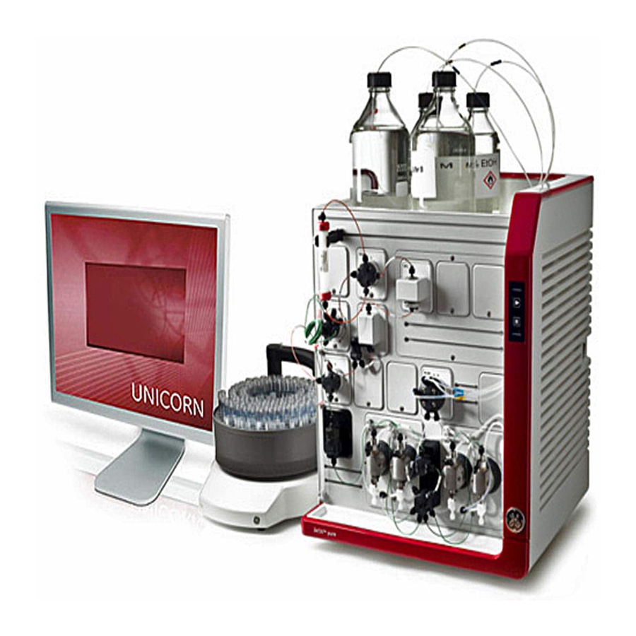
1 Introduction 1.2 ÄKTA pure overview 1.2 ÄKTA pure overview Introduction ÄKTA pure is intended for purification of bio-molecules, in particular proteins, for research purposes by trained laboratory staff members in research laboratories. This section gives an overview of the ÄKTA pure instrument and the UNICORN software. For detailed information about UNICORN, see the UNICORN manuals listed in UNICORN user documentation, on page 13. - Page 11 1 Introduction 1.2 ÄKTA pure overview Module Main functions Method Editor Create and edit methods using one or a combination of: • Predefined methods with built-in application support • Drag-and-drop function to build methods with relevant steps • Line-by-line text editing The interface provides easy viewing and editing of run properties.
-
Page 12: Äkta Pure User Documentation
1 Introduction 1.3 ÄKTA pure user documentation 1.3 ÄKTA pure user documentation Introduction This section describes the user documentation that is delivered with ÄKTA pure. User documentation The user documentation listed in the table below is delivered with ÄKTA pure. It is also available on the user documentation CD. - Page 13 1 Introduction 1.3 ÄKTA pure user documentation UNICORN user documentation The user documentation listed in the following table is available from the Help menu in UNICORN or from the UNICORN Online Help and Documentation software accessed by pressing the F1 key in any UNICORN module.
-
Page 14: The Äkta Pure Instrument
2 The ÄKTA pure instrument 2 The ÄKTA pure instrument About this chapter This chapter provides an overview of the ÄKTA pure instrument. It also describes the internal instrument components and how these are installed in the instrument. In this chapter This chapter contains the following sections: Section See page... -
Page 15: Overview Illustrations
2 The ÄKTA pure instrument 2.1 Overview illustrations 2.1 Overview illustrations Introduction This section provides an overview of the system and its available modules. Core module configurations ÄKTA pure is available with two core module configurations, one for flow rates up to 25 ml/min and one for flow rates up to 150 ml/min. - Page 16 2 The ÄKTA pure instrument 2.1 Overview illustrations Example of a typical configuration of the wet side A typical configuration of ÄKTA pure is illustrated below. Part Function Multi-module panel Inlet valve Pump rinsing liquid tube System pump B Pressure monitor System pump A Mixer Outlet valve...
- Page 17 2 The ÄKTA pure instrument 2.1 Overview illustrations Available modules The modular design allows the user to customize ÄKTA pure in multiple ways. The system is always delivered with the core modules of the selected configuration, but optional modules may be added to the flow path.
- Page 18 2 The ÄKTA pure instrument 2.1 Overview illustrations Module Label in ÄKTA pure 25 ÄKTA pure 150 Conductivity monitor External air sensor L9-1.5 L9-1.5 L9-1.2 L9-1.2 Fraction collectors F9-C F9-C F9-R F9-R I/O-box Sample pump Illustration convention In the valve illustrations below, the following convention is used to point out the location of the ports on the valve head.
- Page 19 2 The ÄKTA pure instrument 2.1 Overview illustrations Core module Description System pump P9 B or P9H B A high precision pump, which delivers buffer in purification runs. For further information, refer to Section 2.4.1 System pumps, on page 34. Pressure monitor R9 Reads the system pressure after System pump A and System pump B.
- Page 20 2 The ÄKTA pure instrument 2.1 Overview illustrations Optional modules Module Description Inlet valve V9-IA or V9H-IA Inlet valve for System pump A with seven inlet ports and integrated air sensor. For further information, refer to Section 2.4.4 Inlet valves, on page 40. V9-IA Inlet valve V9-IB or V9H-IB Inlet valve for System pump B with seven inlet ports and integrated air sensor.
- Page 21 2 The ÄKTA pure instrument 2.1 Overview illustrations Module Description Inlet valve V9-IX or V9H-IX Inlet valve with eight inlet ports. No integrated air sensor. For further information, refer to Section 2.4.4 Inlet valves, on page 40. V9-IX Mixer valve V9-M or V9H-M Directs the flow to the Injection valve, bypassing the Mixer, or to the Injection valve via the Mixer.
- Page 22 2 The ÄKTA pure instrument 2.1 Overview illustrations Module Description Column valve V9-Cs or V9H-Cs Connects a single column to the instrument. Allows the user to chose flow direction through the column, or to bypass the V9-Cs column. For further information, refer to Section 2.4.8 Column valves, on page 56. pH valve V9-pH or V9H-pH Enables the pH electrode to be included in the flow path or bypassed during a run.
- Page 23 2 The ÄKTA pure instrument 2.1 Overview illustrations Module Description Versatile valve V9-V or V9H-V A 4-port, 4-position valve, which can be used when adding extra features to the flow path. V9-V For further information, refer to Section 2.4.9 Versatile valve, on page 60. UV monitor U9-L Measures the UV absorbance at a fixed wavelength of 280 nm.
- Page 24 2 The ÄKTA pure instrument 2.1 Overview illustrations Module Description External air sensor L9-1.5 or L9-1.2 Prevents air from being introduced into the flow path. For further information, refer to Section 3.1 External air sensors, on page 88. Fraction collector F9-C Flexible fraction collector that can collect up to 576 fractions.
- Page 25 2 The ÄKTA pure instrument 2.1 Overview illustrations Module Description Sample pump S9 or S9H A high precision pump with an integrated pressure monitor. The sample pump delivers buffer or sample in purification runs. For further information, refer to Section 3.4 Sample pump S9 and S9H, on page 108.
-
Page 26: Liquid Flow Path
2 The ÄKTA pure instrument 2.2 Liquid flow path 2.2 Liquid flow path Introduction ÄKTA pure is a liquid chromatography system with a flexible flow path. This section provides an overview of the liquid flow path, and its possibilities. Example of a typical liquid flow path The illustration below shows the flow path for a typical system configuration. - Page 27 2 The ÄKTA pure instrument 2.2 Liquid flow path Part Description Inlet valve System pump B System pump A Pressure monitor Mixer Injection valve Sample loop or Superloop Column valve Column UV monitor Conductivity monitor Flow restrictor Outlet valve Fraction collector W, W1, W2 Waste ÄKTA pure User Manual 29119969 AB...
-
Page 28: Instrument Control Panel
2 The ÄKTA pure instrument 2.3 Instrument control panel 2.3 Instrument control panel Introduction This section describes the design and main function of the Instrument control panel B9. Function of the Instrument control panel The Instrument control panel shows the current state of the system. The Pause and Continue buttons can be used to control an ongoing run. - Page 29 2 The ÄKTA pure instrument 2.3 Instrument control panel Lock/Unlock function Follow the instruction below to lock or unlock the Pause and Continue buttons of the Instrument control panel from UNICORN. Step Action In System Control, select System:Settings. Result: The System Settings dialog opens. In the System Settings dialog: •...
- Page 30 2 The ÄKTA pure instrument 2.3 Instrument control panel Status indications The light indicators on the Instrument control panel indicate the current status of ÄKTA pure. The table below describes the different states that can be displayed. Display State Description All light indicators are off.
- Page 31 2 The ÄKTA pure instrument 2.3 Instrument control panel Display State Description Both the Power/Communication indi- A run is ongoing. cator and Continue button display a constant light. The Power/Communication indicator Wash A wash instruction or a pump synchro- displays a constant light and the Con- nization is ongoing.
- Page 32 2 The ÄKTA pure instrument 2.3 Instrument control panel Display State Description The Power/Communication indicator Power-save The system is in power-saving mode. displays a pulsating light. All indicators are lit in a wave pattern. Re-programming A module is being re-programmed to be compatible with the current instru- ment configuration.
-
Page 33: Instrument Modules
2 The ÄKTA pure instrument 2.4 Instrument modules 2.4 Instrument modules Introduction This section describes the design and main functions of the instrument modules. In this section This section contains the following subsections: Section See page 2.4.1 System pumps 2.4.2 Mixer 2.4.3 Valves, overview 2.4.4 Inlet valves 2.4.5 Mixer valve... -
Page 34: System Pumps
2 The ÄKTA pure instrument 2.4 Instrument modules 2.4.1 System pumps 2.4.1 System pumps Introduction This section describes the design and main functions of the system pumps, and also the pump piston rinsing systems. The system can also be equipped with an external, optional sample pump, see Sec- tion 3.4 Sample pump S9 and S9H, on page 108. - Page 35 2 The ÄKTA pure instrument 2.4 Instrument modules 2.4.1 System pumps Location and illustration The illustration below shows the location of System pump A and System pump B, together with a detailed view of a system pump. Part Description Purge valve: Used to remove air from the pump Outlet port with check valve Connections to pump piston rinsing system: Tubing is connected between the pumps and the Pump piston rinsing system tube (6)
- Page 36 2 The ÄKTA pure instrument 2.4 Instrument modules 2.4.1 System pumps Illustration of the pump piston rinsing system Part Description Rinsing system tube holder, top Rinsing system tube Rinsing system tube holder, bottom Outlet tubing Inlet tubing System pump rinsing systems flow path The illustration below shows the tubing configuration of the pump piston rinsing system of the system pumps.
- Page 37 2 The ÄKTA pure instrument 2.4 Instrument modules 2.4.1 System pumps Part Description System pump A System pump B ÄKTA pure User Manual 29119969 AB...
-
Page 38: Mixer
2 The ÄKTA pure instrument 2.4 Instrument modules 2.4.2 Mixer 2.4.2 Mixer Function of the Mixer Mixer M9 is located after System pump A and System pump B, and before the Injection valve. The Mixer is a dynamic mixer for high-performance gradients. It is used to make sure that the buffers from the System pumps are mixed to give a homogenous buffer composition. -
Page 39: Valves, Overview
2 The ÄKTA pure instrument 2.4 Instrument modules 2.4.3 Valves, overview 2.4.3 Valves, overview General design and function of rotary valves The valves of the ÄKTA pure instrument allow flexibility in the liquid flow path. All valves used in the ÄKTA pure instrument are rotary valves. The motorized rotary valve consists of a Valve connection block with a number of defined bores with channels to the inlet and outlet ports of the valve. -
Page 40: Inlet Valves
2 The ÄKTA pure instrument 2.4 Instrument modules 2.4.4 Inlet valves 2.4.4 Inlet valves Function of the inlet valves The inlet valves are used to select which buffers or samples to use in a run. The inlet valves available for ÄKTA pure and their functions are described in the table below. Inlet valve Label in Function... - Page 41 2 The ÄKTA pure instrument 2.4 Instrument modules 2.4.4 Inlet valves • no installed inlet valves. The sample inlet valve can be used together with any of the combinations listed above. The air sensors integrated in Inlet valve A, Inlet valve B, and Sample inlet valve detect the presence of air and prevent the air from entering the pump.
- Page 42 2 The ÄKTA pure instrument 2.4 Instrument modules 2.4.4 Inlet valves Ports of Inlet valve A and Inlet valve B The illustration below shows the ports of Inlet valve A and Inlet valve B, in this example with labels V9- IA and V9-IB.
- Page 43 2 The ÄKTA pure instrument 2.4 Instrument modules 2.4.4 Inlet valves Part Description A inlet ports B inlet ports Outlet port to System pump B Outlet port to System pump A Note: Inlet valve AB does not have any integrated air sensor. Ports of Inlet valve AB The illustration below shows the ports of Inlet valve AB.
- Page 44 2 The ÄKTA pure instrument 2.4 Instrument modules 2.4.4 Inlet valves Illustration of Sample inlet valve The illustration below shows a detailed view of the Sample inlet valve. Part Description Integrated air sensor (located under the plug) Ports of Sample inlet valve The illustration below shows the ports of Sample inlet valve, in this example labeled V9-IS.
- Page 45 2 The ÄKTA pure instrument 2.4 Instrument modules 2.4.4 Inlet valves Ports of Inlet valve IX The illustration below shows the ports of Inlet valve IX. Port Description Inlets For example, to another inlet valve Note: Inlet valve IX does not have an integrated air sensor. Connect tubing The table below shows the tubing and connectors that is delivered together with the optional inlet valves.
- Page 46 2 The ÄKTA pure instrument 2.4 Instrument modules 2.4.4 Inlet valves Tubing Connection Tubing Connector Tubing label length ÄKTA pure 25 ÄKTA pure 150 ÄKTA pure 25 ÄKTA pure 150 (mm) From Inlet valve FEP, o.d. 1/8", FEP, o.d. 3/16", Tubing connec- Tubing connec- A or...
-
Page 47: Mixer Valve
2 The ÄKTA pure instrument 2.4 Instrument modules 2.4.5 Mixer valve 2.4.5 Mixer valve Function of Mixer valve Mixer valve (V9-M or V9H-M) allows the user to bypass the mixer. It is intended to be used when the System pump is used for sample application or when a sample is re-injected. Note: Mixer valve (V9-M or V9H-M) cannot be used together with Sample pump S9 or Sample pump S9H. - Page 48 2 The ÄKTA pure instrument 2.4 Instrument modules 2.4.5 Mixer valve Primary flow path Alternative flow path Port Description Port in which the flow enters the valve. Should be connected to the System pressure monitor outlet. Port from which the flow leaves the Mixer valve and bypasses the Mixer. Connect to the injection valve SaP port.
- Page 49 2 The ÄKTA pure instrument 2.4 Instrument modules 2.4.5 Mixer valve Flow paths through Mixer valve The Mixer valve (V9-M, V9H-M) has two available flow paths; By-pass, and Mixer. If the Mixer valve is installed in the recommended location before the Mixer, By-pass allows the flow to bypass the Mixer, and Mixer directs the flow to the Mixer.
-
Page 50: Injection Valve
2 The ÄKTA pure instrument 2.4 Instrument modules 2.4.6 Injection valve 2.4.6 Injection valve Function of the Injection valve The Injection valve is used to direct sample onto the column. The valve enables usage of a number of different sample application techniques. The injection valve is labeled V9-Inj for ÄKTA pure 25 and V9H-Inj for ÄKTA pure 150. - Page 51 2 The ÄKTA pure instrument 2.4 Instrument modules 2.4.6 Injection valve Primary flow path Alternative flow path Flow path for manual load Closed flow path Port Description Inlet from • sample pump, or • system pump via the Mixer valve Out port. Inlet from the System pumps via the Mixer Syringe connection Outlet to one of the Column valves or to the column.
- Page 52 2 The ÄKTA pure instrument 2.4 Instrument modules 2.4.6 Injection valve Flow path Description Manual load - Default posi- The system flow is directed onto the column or column valve. Sample tion of the valve can be manually injected into the loop. Excess sample leaves the valve through waste port W1.
-
Page 53: Loop Valve
2 The ÄKTA pure instrument 2.4 Instrument modules 2.4.7 Loop valve 2.4.7 Loop valve Function of the Loop valve The Loop valve allows the user to connect several loops simultaneously to the instrument. It can for example be used for storing intermediate fractions in multi-step purifications, for storing samples to be used in scouting runs, or for storing eluents needed in low volumes. - Page 54 2 The ÄKTA pure instrument 2.4 Instrument modules 2.4.7 Loop valve Port Description Port connected to the LoopF port of the Injection valve. 1F and 1E Ports for connection to loop 1. 2F and 2E Ports for connection to loop 2. 3F and 3E Ports for connection to loop 3.
- Page 55 2 The ÄKTA pure instrument 2.4 Instrument modules 2.4.7 Loop valve Connect a Loop valve The Loop valve is connected to the Injection valve instead of a loop, as described below. Step Action Connect port E on the Loop valve to port LoopE on the Injection valve. Connect port F on the Loop valve to port LoopF on the Injection valve.
-
Page 56: Column Valves
2 The ÄKTA pure instrument 2.4 Instrument modules 2.4.8 Column valves 2.4.8 Column valves Function of the Column valves The Column valves are used to connect columns to the system, and to direct the flow onto the column. The Column valves available for ÄKTA pure and their functions are described in the table below. Label in Function ÄKTA pure 25... - Page 57 2 The ÄKTA pure instrument 2.4 Instrument modules 2.4.8 Column valves Part Function Column valve V9-C or V9H-C (integrated pressure sensors) By-pass Note: Maximum one column valve can be installed in ÄKTA pure at any given time. Ports and flow paths of Column valves V9-C and V9H-C The illustration and tables below describe the different ports of and flow paths through Column valves V9-C and V9H-C.
- Page 58 2 The ÄKTA pure instrument 2.4 Instrument modules 2.4.8 Column valves Ports and flow paths of Column valves V9-Cs and V9H-Cs The illustration and tables below describe the different ports and flow paths of Column valve V9-Cs. Port Description Inlet from Injection valve. Port for connection to the top of a column.
- Page 59 2 The ÄKTA pure instrument 2.4 Instrument modules 2.4.8 Column valves Follow the instructions below to connect tubing to the column valves. Step Action If no Column valve is installed, remove the Union F/F between tubing 5 and tubing 6 Connect tubing between Injection valve, Column valve and UV monitor according to the table above.
-
Page 60: Versatile Valve
2 The ÄKTA pure instrument 2.4 Instrument modules 2.4.9 Versatile valve 2.4.9 Versatile valve Function of the Versatile valve The Versatile valve is a 4-port, 4-position valve, which can be used to add extra features to the flow path. For example, the valve can be used to connect external equipment to the flow path during parts of a run. -
Page 61: Ph Valve
2 The ÄKTA pure instrument 2.4 Instrument modules 2.4.10 pH valve 2.4.10 pH valve Function of the pH valve The pH valve is used to direct the flow to a pH electrode when inline monitoring of pH is desired during a run. - Page 62 2 The ÄKTA pure instrument 2.4 Instrument modules 2.4.10 pH valve Ports and flow paths of the pH valve The illustration and table below describe the different ports of and flow paths through the pH valve, in this example labeled V9-pH. By-pass Primary flow path Flow path for calibrations...
- Page 63 2 The ÄKTA pure instrument 2.4 Instrument modules 2.4.10 pH valve Flow path Description By-pass Both pH electrode and Flow restrictor are bypassed. Restrictor Flow restrictor is in use and pH electrode is bypassed. Restrictor Both pH electrode and Flow restrictor are in use. and pH pH electrode is in use and Flow restrictor is bypassed.
- Page 64 2 The ÄKTA pure instrument 2.4 Instrument modules 2.4.10 pH valve Connect tubing The table below shows recommended tubing. Tubing Connection Tubing Connector Tubing label length ÄKTA pure 25 ÄKTA pure 150 (mm) Conductivity monitor PEEK, o.d. 1/16", PEEK, o.d. 1/16", Fingertight connector, to port In i.d.
-
Page 65: Outlet Valves
2 The ÄKTA pure instrument 2.4 Instrument modules 2.4.11 Outlet valves 2.4.11 Outlet valves Function of the outlet valves The outlet valve is used to direct the flow to the fraction collector, to an outlet port, or to waste. The table below shows the labeling of the outlet valves for ÄKTA pure 25 and ÄKTA pure 150. - Page 66 2 The ÄKTA pure instrument 2.4 Instrument modules 2.4.11 Outlet valves Port Description Out1 - Outlet ports 1 - 10 Out10 Frac Port to Fraction collector Note: If a secondary Fraction collector F9-R is used it should be connected to port Out10. Waste port Ports of Outlet valves V9-Os and V9H-Os The illustration below shows the ports of Outlet valve V9-Os.
- Page 67 2 The ÄKTA pure instrument 2.4 Instrument modules 2.4.11 Outlet valves Connect tubing The table below shows recommended tubing and connectors. Tubing Connection Tubing Connector Tubing label length ÄKTA pure 25 ÄKTA pure 150 (mm) Flow restrictor to PEEK, o.d. 1/16", PEEK, o.d.
-
Page 68: Pressure Monitors
2 The ÄKTA pure instrument 2.4 Instrument modules 2.4.12 Pressure monitors 2.4.12 Pressure monitors Introduction This section describes the location and function of the pressure monitors. Up to four pressure monitors are included in ÄKTA pure. Function of the system pump and the sample pump pressure monitors Up to four pressure monitors are included in ÄKTA pure. - Page 69 2 The ÄKTA pure instrument 2.4 Instrument modules 2.4.12 Pressure monitors Function of pressure monitors integrated in Column valves V9-C or V9H-C If Column valve C, labeled V9-C or V9H-C, is used, the two pressure monitors integrated in the valve can be used to monitor the column pressure. Note: Column valve V9-Cs and V9H-Cs does not contain pressure monitors.
-
Page 70: Uv Monitors
The second and third wavelength can be turned off or on in method phase properties, by manual instructions or in system settings. Note: Installation of UV monitor U9-M should only be performed by GE Service personnel. Note: The resolution is decreased when more than one wavelength is used simultaneously due to lower sampling frequency per wavelength. - Page 71 2 The ÄKTA pure instrument 2.4 Instrument modules 2.4.13 UV monitors Function of UV monitor U9-L The UV monitor U9-L measures the UV absorbance at the fixed wavelength of 280 nm. It is not possible to vary the wavelength, or turn on or off the U9-L monitor. This is therefore not shown in the Phase Properties pane in Method Editor.
- Page 72 2 The ÄKTA pure instrument 2.4 Instrument modules 2.4.13 UV monitors Note: When using two UV monitors, the signal from the first UV monitor is by default used for peak fractionation. This can be changed by editing the text instruction Fraction Collection:Peak fractionation parameters:Signal source and choosing UV 2nd as Signal source.
-
Page 73: Conductivity Monitor
2 The ÄKTA pure instrument 2.4 Instrument modules 2.4.14 Conductivity monitor 2.4.14 Conductivity monitor Function of the Conductivity monitor The Conductivity monitor continuously measures the conductivity of buffers and eluted proteins. The monitor is labelled C9. The Conductivity flow cell has two electrodes positioned in the flow path of the cell. An alternating voltage is applied between the electrodes and the resulting current is measured and used to calculate the conductivity of the eluent. - Page 74 2 The ÄKTA pure instrument 2.4 Instrument modules 2.4.14 Conductivity monitor Connect tubing The table below shows recommended tubing and connectors. Tubing Connection Tubing Connector Tubing label length ÄKTA pure 25 ÄKTA pure 150 (mm) UV monitor U9-L to PEEK, o.d. 1/16", PEEK, o.d.
-
Page 75: Flow Restrictor
2 The ÄKTA pure instrument 2.4 Instrument modules 2.4.15 Flow restrictor 2.4.15 Flow restrictor Function of Flow restrictor FR-902 The Flow restrictor is included in the flow path to generate a steady back pressure of approximately 0.2 MPa, to prevent formation of air bubbles in the UV flow cell. Note: Do not remove the flow restrictor to lower the pressure in the system. - Page 76 2 The ÄKTA pure instrument 2.4 Instrument modules 2.4.15 Flow restrictor The illustration below shows Flow restrictor FR-902 fitted on the pH valve. Part Function Flow restrictor Flow restrictor inlet connection from pH valve ToR port Flow restrictor outlet connection to pH valve FrR port ÄKTA pure User Manual 29119969 AB...
-
Page 77: Installation Of Internal Modules
2 The ÄKTA pure instrument 2.5 Installation of internal modules 2.5 Installation of internal modules Introduction Optional modules and valves are easy to install in the instrument. The existing module or Module Panel is removed with a Torx T20 screwdriver and the cable is disconnected. The cable is then connected to the optional module, which is subsequently inserted into the instrument. - Page 78 2 The ÄKTA pure instrument 2.5 Installation of internal modules Step Action Disconnect power from the instrument by switching off the instrument power switch. Loosen the connectors and remove the tubing from the existing module. Note: This step does not apply for a Module Panel. Loosen the module with a Torx T20 screwdriver.
- Page 79 2 The ÄKTA pure instrument 2.5 Installation of internal modules Step Action Connect the cable to the module to be installed. Insert the module. Fasten it with a Torx T20 screwdriver. Note: A warning message is displayed at start up if a module has been installed in the instrument but not added to the current system configuration in UNICORN.
-
Page 80: Accessories
2 The ÄKTA pure instrument 2.6 Accessories 2.6 Accessories Introduction This section describes the holders and other available accessories. These are used to attach and organize columns, tubing and bottles to the ÄKTA pure instrument. The holders are attached to the instrument using the holder rails on the left side and the front of the instrument. - Page 81 2 The ÄKTA pure instrument 2.6 Accessories Loop holder The Loop holder can be used to attach up to five 10 ml sample loops. Use two Multi-purpose holders to attach the holder to a holder rail. The illustration below shows the Loop holder. Part Function Upper attachment to multi-purpose holder...
- Page 82 2 The ÄKTA pure instrument 2.6 Accessories Column clamp The column clamp can be used to attach small sized columns. Use two clamps to attach long columns. The illustration below shows the Column clamp. Part Description Position for a column Inner end tabs Column holder rod The Column holder rod can be used to attach several HiTrap™...
- Page 83 2 The ÄKTA pure instrument 2.6 Accessories Flexible column holder The Flexible column holder can be used to attach, for example, HiScreen™ columns. The illustration below shows the Flexible column holder. Part Function Lower tubing Lower part Snap-in-strips Attachment part Upper tubing Lever Upper part...
- Page 84 2 The ÄKTA pure instrument 2.6 Accessories Tubing holder comb The Tubing holder comb is used to hold and arrange tubing. The illustration below shows the Tubing holder comb. Part Description Positions for tubing Snap-in to holder rails Bottle holder The Bottle holder is used for holding bottles.
- Page 85 2 The ÄKTA pure instrument 2.6 Accessories Module Panel Description All positions in ÄKTA pure must be occupied. Positions not used for core or optional modules must be fitted with a Module Panel. Module Panels are installed in the same way as the other optional modules and the cable inside must be connected to the Module Panel, see Hardware installation of a module, on page 77.
- Page 86 2 The ÄKTA pure instrument 2.6 Accessories Extension box Description The Extension box can be used to install extra modules on the ÄKTA pure instrument outside the system chassis when the positions on the chassis are filled. It is possible to install up to six Extension boxes with extra modules when using ÄKTA pure.
-
Page 87: Äkta Pure External Modules
3 ÄKTA pure external modules 3 ÄKTA pure external modules About this chapter This chapter provides an overview of the external modules that can be connected to the ÄKTA pure instrument. A brief description of how to connect external modules is also provided. In this chapter This chapter contains the following sections: Section... -
Page 88: External Air Sensors
3 ÄKTA pure external modules 3.1 External air sensors 3.1 External air sensors Introduction Up to four external air sensors can be added to ÄKTA pure, and there are two different versions to choose from. They differ in internal diameter and optimal position on the instrument. The air sensors can be attached to the instrument using the rails and holders, see Adapter for air sensor, on page 84. - Page 89 3 ÄKTA pure external modules 3.1 External air sensors Air sensor L9-1.2 Connection Tubing Connector Tubing between... length (mm) Injection valve and L9-1.2 PEEK, o.d. 1/16" Fingertight connector, 1/16" L9-1.2 and Column valve/the PEEK, o.d. 1/16" Fingertight connector, connected column 1/16"...
-
Page 90: Fraction Collector F9-C
3 ÄKTA pure external modules 3.2 Fraction collector F9-C 3.2 Fraction collector F9-C About this section This section shows an overview of Fraction collector F9-C. Technical details are found in the ÄKTA pure User manual. In this section This section contains the following subsections: Section See page 3.2.1 Function... -
Page 91: Function
3 ÄKTA pure external modules 3.2 Fraction collector F9-C 3.2.1 Function 3.2.1 Function Introduction Fraction collector F9-C can collect fractions in deep well plates, tubes of different sizes or bottles. Up to six cassettes for deep well plates and tubes can be used. The cassettes can be used in any combi- nation and are placed on the Cassette tray. - Page 92 3 ÄKTA pure external modules 3.2 Fraction collector F9-C 3.2.1 Function Fractionation arm positions • Home position: The home position is used when the fraction collector is idle. The Fractionation arm is positioned in the front of the interior of the fraction collector and the Dispenser head is positioned over the waste funnel.
-
Page 93: Fraction Collector F9-C Illustrations
3 ÄKTA pure external modules 3.2 Fraction collector F9-C 3.2.2 Fraction collector F9-C illustrations 3.2.2 Fraction collector F9-C illustrations Introduction This section provides illustrations of Fraction collector F9-C. The main features and components are indicated. Front view The illustration below shows the main parts of the exterior of Fraction collector F9-C. Part Description Fractionation indicator... - Page 94 3 ÄKTA pure external modules 3.2 Fraction collector F9-C 3.2.2 Fraction collector F9-C illustrations Rear view The illustration below shows the rear view of Fraction collector F9-C. Part Description Vents UniNet-9 D-type connector (for communication and power supply) Waste tube ÄKTA pure User Manual 29119969 AB...
- Page 95 3 ÄKTA pure external modules 3.2 Fraction collector F9-C 3.2.2 Fraction collector F9-C illustrations Interior The illustration below shows the main parts of the interior of Fraction collector F9-C. Part Description Fractionation arm guide rail Fractionation arm main rail Lamp Tubing guide Tubing connection Dispenser head...
- Page 96 3 ÄKTA pure external modules 3.2 Fraction collector F9-C 3.2.2 Fraction collector F9-C illustrations Dispenser head The illustration below shows the Dispenser head of Fraction collector F9-C. Part Description Dispenser head Nozzle Dispenser head cover Accumulator (back part of Dispenser head) Drop sync sensor Type code reader ÄKTA pure User Manual 29119969 AB...
-
Page 97: Cassettes, Cassette Tray And Racks
The illustrations below show the Cassette tray, the Rack for 50 ml tubes and the Rack for 250 ml bottles. The fronts of the tray and the racks are marked with the GE-logotype. In the Cassette tray, the cassette positions are marked 1 to 6. - Page 98 3.2.3 Cassettes, Cassette tray and racks Note: The tray and racks are inserted into the fraction collector with the GE-logotype facing outwards. Note: Do not use the Cassette tray when a rack for tubes or bottles is placed in the fraction collector.
- Page 99 3 ÄKTA pure external modules 3.2 Fraction collector F9-C 3.2.3 Cassettes, Cassette tray and racks QuickRelease function The Cassettes for the smaller tube sizes (3, 8, and 15 ml) have a built-in QuickRelease function. The QuickRelease function enables easy handling of tubes in the Cassettes. With the QuickRelease device in lock position the tubes are fastened in the Cassette and can easily be emptied.
- Page 100 3 ÄKTA pure external modules 3.2 Fraction collector F9-C 3.2.3 Cassettes, Cassette tray and racks Step Action Empty and discard the remaining tubes: • Press the QuickRelease device to the lock position, and empty the remaining tubes. • Pull the QuickRelease device to the release position, and discard the tubes. Empty the tubes Discard the tubes Fraction collector tubes and bottles...
- Page 101 Shape of wells Square, not cylindrical Well volume 10, 5, or 2 ml Approved deep well plates The plates listed in the table below are tested and approved by GE to be used with Fraction collector F9-C. Plate type Manufacturer Part no.
- Page 102 3 ÄKTA pure external modules 3.2 Fraction collector F9-C 3.2.3 Cassettes, Cassette tray and racks Plate type Manufacturer Part no. 24 deep well plate 7701-5102 (Whatman) Seahorse Bioscience S30024 Maximum flow rate Fraction collection can be performed at different maximum flow rates depending on what type of deep well plates that are used.
-
Page 103: Connect Tubing To The Äkta Pure Instrument
3 ÄKTA pure external modules 3.2 Fraction collector F9-C 3.2.4 Connect tubing to the ÄKTA pure instrument 3.2.4 Connect tubing to the ÄKTA pure instrument Connect tubing Fraction collector F9-C is delivered with all internal tubing in place. The tubing between the fraction collector and purification instrument need to be installed. -
Page 104: Fraction Collector F9-R
3 ÄKTA pure external modules 3.3 Fraction collector F9-R 3.3 Fraction collector F9-R About this section This section shows an overview of Fraction collector F9-R. Technical details are found in the ÄKTA pure User manual and ÄKTA avant User manual. Function The fraction collector collects fractions from ÄKTA pure purification runs. - Page 105 3 ÄKTA pure external modules 3.3 Fraction collector F9-R Part Function Lock knob Stationary part of delivery arm Delivery arm Tubing connector Tube sensor Collection tubes Tube rack Base unit Connector panel illustration The illustration below shows the main parts of the connector panel on the fraction collector. Part Function Node ID switch...
- Page 106 3 ÄKTA pure external modules 3.3 Fraction collector F9-R Available tubes For Fraction collector F9-R the fractions are collected in tubes of different sizes. Tubes with the following diameter can be used with Fraction collector F9-R: • 12 mm • 18 mm •...
- Page 107 3 ÄKTA pure external modules 3.3 Fraction collector F9-R Connect tubing to ÄKTA pure Step Action Lift out the Tubing holder (4) from the Delivery arm (1). Loosen the nut of the Tubing holder. Do not remove the Tubing holder nut (5) from the Tubing holder.
-
Page 108: Sample Pump S9 And S9H
3 ÄKTA pure external modules 3.4 Sample pump S9 and S9H 3.4 Sample pump S9 and S9H Introduction This section describes the design and function of Sample pump S9 and S9H. Function of the Sample pump The Sample pump is dedicated to direct loading of sample onto a column, or to filling of sample loops or Superloops. - Page 109 3 ÄKTA pure external modules 3.4 Sample pump S9 and S9H Part Function Pump head: Encapsulates the inner parts of the pump Pump rinsing liquid tube holder Outlet port with check valves Purge valve: Used to remove air from the pump Sample pump outlet port Sample pressure monitor Vents...
- Page 110 3 ÄKTA pure external modules 3.4 Sample pump S9 and S9H Sample pump piston rinsing system A seal prevents leakage between the pump chamber and the drive mechanism. The seal is continuously lubricated by the presence of solvent. The pump piston rinsing system continuously flushes the low pressure chamber behind the piston with a low flow of 20% ethanol.
- Page 111 3 ÄKTA pure external modules 3.4 Sample pump S9 and S9H Connect tubing to the ÄKTA pure instrument The table below shows recommended tubing and connectors. Tubing Connection Tubing Connector Tubing label length ÄKTA ÄKTA ÄKTA pure 25 ÄKTA pure 150 (mm) pure 25 pure 150...
-
Page 112: I/O-Box E9
3 ÄKTA pure external modules 3.5 I/O-box E9 3.5 I/O-box E9 About this section This section describes the design and the function of the I/O-box E9 In this section This section contains the following subsections: Section See page 3.5.1 Overview of the I/O-box 3.5.2 Analog connector and signals 3.5.3 Digital connector and signals 3.5.4 Connect external equipment to the I/O-box... -
Page 113: Overview Of The I/O-Box
3 ÄKTA pure external modules 3.5 I/O-box E9 3.5.1 Overview of the I/O-box 3.5.1 Overview of the I/O-box Function of the I/O-box The I/O-box E9 is used to interface other equipment in order to measure parameters such as refractive index, light scattering and fluorescence. See Requirements on connected equipment, on page 119 for information on requirements of the equipment that can be connected to ÄKTA pure. - Page 114 3 ÄKTA pure external modules 3.5 I/O-box E9 3.5.1 Overview of the I/O-box Connectors Part Description Analog in/out Signal connector for analog input and output signals. UniNet-9 Connector used to connect the I/O-box to the ÄKTA pure instru- ment. Status Status indicator for service purposes.
-
Page 115: Analog Connector And Signals
3 ÄKTA pure external modules 3.5 I/O-box E9 3.5.2 Analog connector and signals 3.5.2 Analog connector and signals Analog connector pins Part Function Analog in signal 1 + Analog in signal 1 - (or signal ground) Shield, analog in (both ports) Analog in signal 2 + Analog in signal 2 - (or signal ground) Calibration pin for service purposes... - Page 116 3 ÄKTA pure external modules 3.5 I/O-box E9 3.5.2 Analog connector and signals Analog input signals There are two analog input channels from which analog input signals can be used for peak detection, or data collection in UNICORN. It is possible to auto-zero the input signals, which means that the current value will be displayed as 0 V in UNICORN.
-
Page 117: Digital Connector And Signals
3 ÄKTA pure external modules 3.5 I/O-box E9 3.5.3 Digital connector and signals 3.5.3 Digital connector and signals Digital connector pins Part Function Digital in signal 1 Digital in signal 2 Digital in signal 3 Digital in signal 4 Signal ground Digital out signal 1 Digital out signal 2 Digital out signal 3... - Page 118 3 ÄKTA pure external modules 3.5 I/O-box E9 3.5.3 Digital connector and signals Input connection UNICORN interpretation Open circuit Logical 1 Applied voltage 3.5 to 5.0 V Closed circuit Logical 0 Applied voltage 0 to 0.8 V Digital output signals The digital output signal can be used to control external equipment that can receive digital signals, such as pumps or fraction collectors.
-
Page 119: Connect External Equipment To The I/O-Box
3 ÄKTA pure external modules 3.5 I/O-box E9 3.5.4 Connect external equipment to the I/O-box 3.5.4 Connect external equipment to the I/O-box Requirements on connected equipment The physical requirements for the connected equipment is described in the following tables. All con- nected equipment must have a common grounding. - Page 120 3 ÄKTA pure external modules 3.5 I/O-box E9 3.5.4 Connect external equipment to the I/O-box • Wire stripping tool Instruction Follow the instructions to connect one or two external cables to the supplied D-sub connectors. Step Action Open the connector housing by removing housing screw and unlatch the housing top shell using a flat-blade screwdriver.
- Page 121 3 ÄKTA pure external modules 3.5 I/O-box E9 3.5.4 Connect external equipment to the I/O-box System settings Default values for digital out ports, noise reduction and configuration of analog out ports can be set. Instruction name Description Digital out X Sets the value of the signal sent out by digital port number X to either 0 or 1.
-
Page 122: Connection Of External Modules
3 ÄKTA pure external modules 3.6 Connection of external modules 3.6 Connection of external modules Introduction The external modules are not installed in the instrument cabinet, but are connected via a UniNet-9 cable at the back of the system. it is possible to install up to six external modules with F-type connectors and up to two external modules with D-type connectors at the same time. - Page 123 3 ÄKTA pure external modules 3.6 Connection of external modules External module Connector Constraints Fraction collector F9-R, 2nd F-type Fraction collector F9-R, 2nd requires Fraction collector F9-R or Fraction collector F9-C. Sample pump S9 and S9H D-type Cannot be used at the same time as Mixer valve V9-M or V9H-M.
-
Page 124: System Configuration
4 System configuration 4 System configuration About this chapter This chapter describes hardware configuration of the ÄKTA pure instrument and how to install optional modules and add them in UNICORN. In this chapter This chapter contains the following sections: Section See page 4.1 Configuration overview 4.2 Configure modules... -
Page 125: Configuration Overview
4 System configuration 4.1 Configuration overview 4.1 Configuration overview Introduction ÄKTA pure is a flexible system that allows the user to configure both hardware and software to meet many purification needs. The instrument can be easily extended with additional valves, detectors and fraction collectors. - Page 126 4 System configuration 4.1 Configuration overview Recommended module position Module Recommended location Constraints Column valve V9-C or Column valve V9-C or V9H-C cannot be V9H-C used at the same time as Column valve V9-Cs or V9H-Cs. Column valve V9-Cs or Column valve V9-Cs or V9H-Cs cannot V9H-Cs be used at the same time as Column...
- Page 127 4 System configuration 4.1 Configuration overview Module Recommended location Constraints pH valve V9-pH or V9H-pH pH valve shall always be connected after the column due to pressure constraints and fractionation control. The delay vol- ume calculations will be effected if the valve is located elsewhere.
- Page 128 4 System configuration 4.1 Configuration overview Install the modules Detailed information about installation of the modules is found in Chapter 2 The ÄKTA pure instrument, on page 14 and Chapter 3 ÄKTA pure external modules, on page 87. Below is a quick guide of how to perform a module hardware installation. Step Action Switch off the power.
- Page 129 4 System configuration 4.1 Configuration overview Step Action • In the Administration module, choose Tools:System Properties or click the System Properties icon to open the dialog. Result: The System Properties dialog is displayed. • Select the system of interest in the System Properties dialog. •...
- Page 130 4 System configuration 4.1 Configuration overview There are five main types of modules (named components in UNICORN) to select from: • Valves and pumps • Monitors and sensors • Fraction collectors • Other (e.g., I/O-box) • Core components (always present) Multiple choices are not shown unless a component has been selected.
-
Page 131: Configure Modules
4 System configuration 4.2 Configure modules 4.2 Configure modules In this section This section describes the software configuration that must be set for the individual modules that are to be used for a specific run. A general description of how to update the system properties are found in Edit system properties, on page 128. -
Page 132: Configuration Of Inlet Valves
4 System configuration 4.2 Configure modules 4.2.1 Configuration of inlet valves 4.2.1 Configuration of inlet valves System properties Follow the instruction below to update the system properties. Step Action Open the system properties Edit dialog. Select Valves and pumps from the Component types list. Select components and properties according to the following table: Valve Component selection... -
Page 133: Configuration Of Mixer Valves
4 System configuration 4.2 Configure modules 4.2.2 Configuration of Mixer valves 4.2.2 Configuration of Mixer valves System properties Follow the instruction below to update the system properties. Step Action Open the system properties Edit dialog. Select Valves and pumps from the Component types list. Select Mixer valve (V9-M) or Mixer valve (V9H-M) in the Component selection list. -
Page 134: Configuration Of Loop Valves
4 System configuration 4.2 Configure modules 4.2.3 Configuration of Loop valves 4.2.3 Configuration of Loop valves System properties Follow the instruction below to update the system properties. Step Action Open the system properties Edit dialog. Select Valves and pumps from the Component types list. Select Loop valve (V9-L) or Loop valve (V9H-L) in the Component selection list. -
Page 135: Configuration Of Column Valves
4 System configuration 4.2 Configure modules 4.2.4 Configuration of column valves 4.2.4 Configuration of column valves System properties Follow the instruction below to update the system properties. Step Action Open the system properties Edit dialog. Select Valves and pumps from the Component types list. Select components and properties according to the following table: Valve Component selection... - Page 136 4 System configuration 4.2 Configure modules 4.2.4 Configuration of column valves Step Action • Select a system. • Select Control mode. • Click OK. Result: The selected instrument can now be controlled by the software. • Select Tubing and Delay Volumes and select Tubing: Injection valve to column. •...
-
Page 137: Configuration Of Versatile Valves
4 System configuration 4.2 Configure modules 4.2.5 Configuration of Versatile valves 4.2.5 Configuration of Versatile valves System properties Follow the instruction below to update the system properties. Step Action Open the system properties Edit dialog. Select Valves and pumps from the Component types list. Select Versatile valve (V9-V), Versatile valve 2 (V9-V), Versatile valve 3 (V9-V) or Versatile valve 4 (V9-V) in the Component selection list. -
Page 138: Configuration Of Ph Valves
4 System configuration 4.2 Configure modules 4.2.6 Configuration of pH valves 4.2.6 Configuration of pH valves System properties Follow the instruction below to update the system properties. Step Action Open the system properties Edit dialog. Select Valves and pumps from the Component types list. Select pH valve (V9-pH) or pH valve (V9H-pH) in the Component selection list. -
Page 139: Configuration Of Outlet Valves
4 System configuration 4.2 Configure modules 4.2.7 Configuration of outlet valves 4.2.7 Configuration of outlet valves System properties Follow the instruction below to update the system properties. Step Action Open the system properties Edit dialog. Select Valves and pumps from the Component types list. Select components and properties according to the following table: Valve Component selection... -
Page 140: Configuration Of Uv Monitors
4 System configuration 4.2 Configure modules 4.2.8 Configuration of UV monitors 4.2.8 Configuration of UV monitors Using two UV monitors The UV monitor U9-L module can be used in two configurations, UV monitor U9-L and UV monitor U9- L, 2nd. The configuration is defined by the module's Node ID. It is possible to use two UV monitors in ÄKTA pure, in the following combinations: •... -
Page 141: Configuration Of Conductivity Monitor
4 System configuration 4.2 Configure modules 4.2.9 Configuration of Conductivity monitor 4.2.9 Configuration of Conductivity monitor System properties Follow the instruction below to update the system properties. Step Action Open the system properties Edit dialog. Select Monitors and sensors from the Component types list. Select Conductivity monitor (C9) in the Component selection list. -
Page 142: Configuration Of External Air Sensors
4 System configuration 4.2 Configure modules 4.2.10 Configuration of external air sensors 4.2.10 Configuration of external air sensors System properties Follow the instruction below to update the system properties. Step Action Open the system properties Edit dialog. Select Monitors and sensors from the Component types list. Select External air sensor (L9) in the Component selection list, or the appropriate com- ponent if multiple external air sensors are used. -
Page 143: Configuration Of Fraction Collectors
4 System configuration 4.2 Configure modules 4.2.11 Configuration of fraction collectors 4.2.11 Configuration of fraction collectors System properties Follow the instruction below to update the system properties. Step Action Open the system properties Edit dialog. Select Fraction collectors from the Component types list. Select components and properties according to the following table: Fraction collector Component selection... - Page 144 4 System configuration 4.2 Configure modules 4.2.11 Configuration of fraction collectors Instruction name Description Fraction collector lamp Fraction collector lamp: Lamps in the fraction collector chamber on or off. Peak fractionation parameters The Peak fractionation parameters set the detection parameters for peak collection, that is they decide when a peak starts and ends.
-
Page 145: Configuration Of I/O-Box
4 System configuration 4.2 Configure modules 4.2.12 Configuration of I/O-box 4.2.12 Configuration of I/O-box System properties Follow the instruction below to update the system properties. Step Action Open the system properties Edit dialog. Select Monitors and sensors from the Component types list. Select I/O-box (E9) or I/O-box 2 (E9) in the Component selection list. -
Page 146: General System Settings
4 System configuration 4.3 General system settings 4.3 General system settings Check/Set delay volume When a module has been installed after the UV monitor in the flow path, the delay volume has to be adjusted in the System Setting dialog in UNICORN, to make sure that the collected fractions correspond to the fractions indicated in the chromatogram. - Page 147 4 System configuration 4.3 General system settings Lock/Unlock function Follow the instruction below to lock or unlock the Pause and Continue buttons of the Instrument control panel from UNICORN. Step Action In System Control, select System:Settings. Result: The System Settings dialog opens. In the System Settings dialog: •...
- Page 148 4 System configuration 4.3 General system settings Follow the instructions below to activate Power-save. Step Action Select System:Settings in the System Control module. Result: The System Settings dialog opens. • Select Advanced • select Power-save • Select On in the Mode field •...
-
Page 149: Operation
5 Operation 5 Operation About this chapter This chapter describes the steps involved when operating ÄKTA pure. In this chapter This chapter contains the following sections: Section See page 5.1 Before you prepare the system 5.2 Prepare the flow path 5.3 Start UNICORN and connect to system 5.4 Prime inlets and purge pump heads 5.5 Connect a column... -
Page 150: Before You Prepare The System
5 Operation 5.1 Before you prepare the system 5.1 Before you prepare the system Introduction It is important to prepare the system in accordance with the settings in the method to be run. Before preparing the system, check the settings in the Method Editor and make sure that all accessories to be used are available. -
Page 151: Prepare The Flow Path
5 Operation 5.2 Prepare the flow path 5.2 Prepare the flow path Introduction The flow path is defined by the user and may contain tubing, valves, pumps and monitors. This section gives an overview of a flow path and describes how to prepare the flow path before a run. Illustration of the flow path The illustration below shows the flow path for a typical system configuration. - Page 152 5 Operation 5.2 Prepare the flow path Part Description Inlet valve System pump B System pump A Pressure monitor Mixer Injection valve Sample loop or Superloop Column valve Column UV monitor Conductivity monitor Flow restrictor Outlet valve Fraction collector W, W1, W2 Waste Select Mixer chamber To obtain a homogeneous buffer composition, it is important to use a Mixer chamber suitable for the...
- Page 153 5 Operation 5.2 Prepare the flow path CAUTION Risk of explosion. Do not use Mixer chamber 15 ml with an ÄKTA pure 25 configura- tion. The maximum pressure for Mixer chamber 15 ml is 5 MPa. Note: In ÄKTA pure 25 at low flow rates (below 0.2 ml/min) a gradient of sufficient quality may be achieved with the mixer bypassed.
- Page 154 5 Operation 5.2 Prepare the flow path Prepare the outlet tubing Connect outlet tubing to the outlet ports of Outlet valve that are to be used. If a fraction collector is to be used, make sure that tubing is connected as described in Connect tubing, on page 103 and Connect tubing to ÄKTA pure, on page 107, and prepare the fraction collector.
- Page 155 5 Operation 5.2 Prepare the flow path Waste tubing overview The table below lists the waste tubing of the instrument and where it is located. Make sure that the waste tubing is connected to the correct positions on the modules. Module Tubing connections Location of tubing...
- Page 156 5 Operation 5.2 Prepare the flow path Step Action Insert the waste tubing from all installed modules, in this example Injection valve, Outlet valve (W, W1 and W2) and the fraction collector, in a vessel. Make sure that the tubing is securely fastened to the ÄKTA pure instrument: •...
- Page 157 5 Operation 5.2 Prepare the flow path Step Action Cut the waste tubing to appropriate length. It is important that the tubing is not bent and will not be submerged in liquid during the run. Note: If the tubing is too short, replace it with new tubing. Do not lengthen the tubing as this might cause obstruction of the tubing.
-
Page 158: Start Unicorn And Connect To System
5 Operation 5.3 Start UNICORN and connect to system 5.3 Start UNICORN and connect to system Introduction This section describes how to start and log on to UNICORN and how to connect the instrument to UNICORN. Start UNICORN and log on Follow the instructions to start UNICORN and log on to the program. - Page 159 5 Operation 5.3 Start UNICORN and connect to system Connect to system Follow the instructions to connect the instrument to UNICORN. Step Action In the System Control module, • Click the Connect to Systems button, • click Connect to Systems on the System menu. Result: The Connect to Systems dialog opens.
- Page 160 5 Operation 5.3 Start UNICORN and connect to system Step Action In the Connect to systems dialog: • Select the checkbox in front of the system name. • To control the selected system, click Control. • Click OK. Result: The instrument control panel displays a white, rapidly flashing light followed by a steady white light when the system is ready.
-
Page 161: Prime Inlets And Purge Pump Heads
5 Operation 5.4 Prime inlets and purge pump heads 5.4 Prime inlets and purge pump heads About this section Before usage of a pump, it is important to: • Prime the inlets (fill the buffer inlets with liquid). • Purge the pump (remove air from the pump heads). This section describes how to prime inlets and purge the pump heads of the system pumps and the sample pump (the sample pump is an optional module). -
Page 162: System Pumps
5 Operation 5.4 Prime inlets and purge pump heads 5.4.1 System pumps 5.4.1 System pumps Introduction This section describes how to prime inlets and purge the System pumps. Overview The procedure consists of the following stages: Stage Description Prime all inlet tubing to be used during the run Purge System pump B Validate purge of System pump B Purge System pump A... - Page 163 5 Operation 5.4 Prime inlets and purge pump heads 5.4.1 System pumps Step Action In the Process Picture: • Click on the buffer inlets. • Select the position of the inlet to be filled. Select the positions in reverse alphabetical order and start with the highest number.
- Page 164 5 Operation 5.4 Prime inlets and purge pump heads 5.4.1 System pumps Step Action In the Process Picture: • Click on the Injection valve and select System pump waste. Result: The Injection valve switches to waste position. This is necessary to achieve a low back pressure during the purge procedure.
- Page 165 5 Operation 5.4 Prime inlets and purge pump heads 5.4.1 System pumps Step Action In the Process Picture: • Click on the buffer inlets. • Select the position of one of the inlets that will be used at the beginning of the run. Result: The inlet valve switches to the selected port.
- Page 166 5 Operation 5.4 Prime inlets and purge pump heads 5.4.1 System pumps Step Action Connect the syringe to the purge valve on the right pump head of System pump B, and repeat steps 6 to 8. Keep the system flow running. Validate purge of pump B Follow the instructions below to check that there is no air left in the pump after performing a purge.
- Page 167 5 Operation 5.4 Prime inlets and purge pump heads 5.4.1 System pumps Purge System pump A Purge both pump heads of System pump A by following the same procedure as in Purge System pump B, on page 163, but replace step 3 with the following actions: In the Process Picture: •...
-
Page 168: Sample Pump
5 Operation 5.4 Prime inlets and purge pump heads 5.4.2 Sample pump 5.4.2 Sample pump Introduction This section describes how to prime inlets and purge Sample pumps S9 and S9H. Overview The procedure consists of the following steps: 1 Prime all sample inlet tubing to be used during the run 2 Purge the Sample pump 3 Validate purge 4 End the run... - Page 169 5 Operation 5.4 Prime inlets and purge pump heads 5.4.2 Sample pump Step Action In the Process Picture : • Click on Sample inlet valve. • Select the position of the inlet to be filled. Start at the inlet position with the highest number and end at the position with the lowest number.
- Page 170 5 Operation 5.4 Prime inlets and purge pump heads 5.4.2 Sample pump Purge the Sample pump Follow the instruction below to purge both the pump heads of the Sample pump. Step Action Make sure that all sample inlet tubing that is to be used during the method run is immersed in the correct buffers.
- Page 171 5 Operation 5.4 Prime inlets and purge pump heads 5.4.2 Sample pump Step Action Connect a 25 to 30 ml syringe to the left purge valve of the Sample pump. Make sure that the syringe fits tightly into the purge connector. Open the purge valve by turning it counter-clockwise about three-quarters of a turn.
- Page 172 5 Operation 5.4 Prime inlets and purge pump heads 5.4.2 Sample pump Validate purge Follow the instructions below to check that there is no air left in the pump after performing a purge. Step Action In the Process Picture: • Click on the Injection valve and select Direct inject. Result: The Injection valve switches to direct inject position.
-
Page 173: Connect A Column
5 Operation 5.5 Connect a column 5.5 Connect a column Introduction This section describes how to connect a column to the instrument using a column holder and without introducing air into the flow path. Several types of column holders are available for ÄKTA pure. WARNING To avoid exposing the column to excessive pressure, make sure that the pressure limit is set to the specified maximum pressure of the column. - Page 174 5 Operation 5.5 Connect a column Step Action Attach the column to the column holder. Connect a suitable tubing to a Column valve port, in this example port 1A. Open the System Control module. In the Process Picture: • Click on the Column. •...
- Page 175 5 Operation 5.5 Connect a column Step Action In the Process Picture: • Click on the Pumps. • Enter a low System flow (e.g., 0.2 ml/min). • Click Set flow rate. Result: A system flow of 0.2 ml/min starts. When buffer leaves the tubing in a continuous mode and the top part of the column is filled with buffer, connect the tubing to the top of the column.
- Page 176 5 Operation 5.5 Connect a column Step Action When buffer leaves the tubing at the bottom of the column in a continuous mode, connect this piece of tubing to the Column valve. Use the port opposite to the one already con- nected to the column, in this example port 1B.
-
Page 177: Pressure Alarms
5 Operation 5.6 Pressure alarms 5.6 Pressure alarms Introduction The columns can be protected by two different types of pressure alarms: • The pre-column pressure alarm protects the column hardware • The delta-column pressure alarm (only available when V9-C or V9H-C is installed) protects the column media Column valves V9-C and V9H-C have built-in pressure sensors that automatically measure the pre- column and delta-column pressure. - Page 178 5 Operation 5.6 Pressure alarms Step Action • Select the inner diameter of the tubing between the injection valve and the column from the I.D. drop-down list. • Type in the tubing Length. If the sample pump is used: • Select Tubing: Sample pump to injection. •...
- Page 179 5 Operation 5.6 Pressure alarms Step Action • Select Alarms • select Alarm pre column pressure. Select Enabled in the Mode field. • Type the high pressure limit in the High alarm field. • Click Execute. ÄKTA pure User Manual 29119969 AB...
-
Page 180: Sample Application
5 Operation 5.7 Sample application 5.7 Sample application Introduction This section describes the different sample application techniques that can be used with ÄKTA pure. The table below shows the alternatives for sample application available in the Sample application phase of a method. Sample application Compatible loops Inject sample directly... -
Page 181: Sample Application Using Direct Injection Onto The Column
5 Operation 5.7 Sample application 5.7.1 Sample application using direct injection onto the column 5.7.1 Sample application using direct injection onto the column Introduction There are two ways to load sample directly onto a column: • a fixed volume is loaded, or •... - Page 182 5 Operation 5.7 Sample application 5.7.1 Sample application using direct injection onto the column When preparing to inject... Then... all the sample • in the Method editor, make the following selections for the Sample Application phase of the method to be run: - select Inject sample directly onto column, and - select Inject all sample using air sensor.
-
Page 183: Sample Application Using A Superloop
5 Operation 5.7 Sample application ™ 5.7.2 Sample application using a Superloop 5.7.2 Sample application using a Superloop ™ Introduction A Superloop allows injection of large sample volumes onto the column. A Superloop can also be used for multiple injections, for example in a scouting experiment when the same application conditions are required. - Page 184 5 Operation 5.7 Sample application ™ 5.7.2 Sample application using a Superloop Step Action Connect a piece of tubing from the bottom of the Superloop to: • port LoopF on the Injection valve • the F port corresponding to the connected E port, eg., 1F, on the Loop valve Fill the Superloop using a syringe Follow the instruction below to fill the Superloop using a syringe.
- Page 185 5 Operation 5.7 Sample application ™ 5.7.2 Sample application using a Superloop Step Action If the loop is connected to: • the Injection valve, continue to step 5. • the Loop valve, continue to step 4. In the Process Picture: •...
- Page 186 5 Operation 5.7 Sample application ™ 5.7.2 Sample application using a Superloop Step Action In the Manual instructions dialog: • Select Flow path:Injection valve. • Select Sample pump load from the Position drop-down list. • Click Result: The Injection valve switches to Sample pump load position. Make sure that the sample inlet tubing from the sample vessel is connected to the Sample inlet valve.
- Page 187 5 Operation 5.7 Sample application ™ 5.7.2 Sample application using a Superloop Fill the Superloop using System pump A Follow the instruction below to fill the Superloop using the System pump A. Note that Mixer valve has to be installed for this loop filling technique. NOTICE Glass tube splinter.
- Page 188 5 Operation 5.7 Sample application ™ 5.7.2 Sample application using a Superloop Step Action In the Process Picture: • Click the Mixer valve and select By-pass. Result: The Mixer valve switches to By-pass position. If the loop is connected to: •...
- Page 189 5 Operation 5.7 Sample application ™ 5.7.2 Sample application using a Superloop Step Action In the Process Picture: • Click on the Pumps. • Set the System flow to an appropriate value for the Superloop size, in this example 10 ml/min. •...
-
Page 190: Sample Application Using A Sample Loop
5 Operation 5.7 Sample application 5.7.3 Sample application using a sample loop 5.7.3 Sample application using a sample loop Introduction A sample loop is recommended for injection of smaller sample volumes onto the column. A sample loop can be connected to either the Injection valve or the Loop valve. When using the Loop valve, up to five loops can be connected simultaneously. - Page 191 5 Operation 5.7 Sample application 5.7.3 Sample application using a sample loop Step Action In the Process Picture: • Click on the Injection valve and select Manual load. Result: Injection valve is set to manual load. If the loop is connected to: •...
- Page 192 5 Operation 5.7 Sample application 5.7.3 Sample application using a sample loop Step Action Load sample into the sample loop. To avoid sample loss due to siphoning, leave the syringe in the port until the sample has been injected onto the column during the run. Tip: It is recommended to overfill the loop to make sure that the loop is completely filled.
-
Page 193: Fractionation
5 Operation 5.8 Fractionation 5.8 Fractionation Introduction Fraction collector F9-C and Fraction collector F9-R collect fractions from ÄKTA pure purification runs. The fraction collectors are connected to ÄKTA pure and controlled by UNICORN. Control of the fraction collector can be achieved automatically in a method run, or manually. In this section This section contains the following subsections: Section... -
Page 194: Prepare Fraction Collector F9-C
5 Operation 5.8 Fractionation 5.8.1 Prepare Fraction collector F9-C 5.8.1 Prepare Fraction collector F9-C About this section This section describes how to prepare and assemble Fraction collector F9-C before a run. The fraction collector is connected to ÄKTA pure and controlled by UNICORN. Control of the fraction collector can be achieved automatically in a method run, or manually. - Page 195 5 Operation 5.8 Fractionation 5.8.1 Prepare Fraction collector F9-C Prepare and insert the Cassette tray Follow the instructions below to add cassettes to the Cassette tray and insert the tray into the fraction collector. Step Action If you are to use cassettes with the QuickRelease function, open the cassettes. For more information on the QuickRelease function see QuickRelease function, on page 99.
- Page 196 Close the cassettes that have the QuickRelease function. Place the cassettes on the Cassette tray. Make sure that the cassette type code (see illus- tration below) faces the front of the tray marked with the GE logo. Open the door of the fraction collector using the handle.
- Page 197 Action Insert the tray into the fraction collector: • make sure that the front of the tray (marked with the GE logo) faces outwards • position the tray and slide it into the fractionation collector until it reaches the end •...
- Page 198 Open the door of the fraction collector using the handle. Insert the rack into the fraction collector: • make sure that the front of the rack (marked with the GE logo) faces outwards • position the rack and slide it into the fractionation collector until it reaches the end •...
- Page 199 5 Operation 5.8 Fractionation 5.8.1 Prepare Fraction collector F9-C Step Action Close the door. Make sure that it closes properly. Note: If the rack is inserted with the front of the rack facing the wrong way it will not be possible to close the door.
-
Page 200: Prepare Fraction Collector F9-R
5 Operation 5.8 Fractionation 5.8.2 Prepare Fraction collector F9-R 5.8.2 Prepare Fraction collector F9-R Introduction This chapter describes how to prepare and assemble Fraction collector F9-R before a run. Fraction collector F9-R is connected to ÄKTA pure and controlled by UNICORN. Control of the fraction collector can be achieved automatically in a method run, or manually. - Page 201 5 Operation 5.8 Fractionation 5.8.2 Prepare Fraction collector F9-R Tube rack inserts The Fraction collector F9-R is delivered with the 18 mm tube rack mounted. Each tube rack is made up of a combination of a Bowl, Tube support, Tube guide and Tube holder. Change the Tube holder and the Tube guide to collect fractions in 12 mm tubes or 30 mm tubes.
- Page 202 5 Operation 5.8 Fractionation 5.8.2 Prepare Fraction collector F9-R Assembly instructions Follow the instructions below to assemble the Tube rack. Step Action Insert the Tube support (4), if required, into the bowl (3). The circular marks on the Tube support should face down. Note: When assembling a Tube rack, Single cutouts (1) and L-shaped cutouts (2), are used for various inserts depending on the length of the collection tubes.
- Page 203 5 Operation 5.8 Fractionation 5.8.2 Prepare Fraction collector F9-R Step Action • Push the flexible bowl out at each rib and snap the Tube holder under the top lip of the rib (8). Note: Do not force the tube holder into place as this may damage the lip. •...
- Page 204 5 Operation 5.8 Fractionation 5.8.2 Prepare Fraction collector F9-R Insert collection tubes Insert a sufficient number of collection tubes in to the Tube rack, starting at position 1, pushing each one down as far as they will go. All the tubes must be of the same length and diameter and there should be no spaces in the sequence.
- Page 205 5 Operation 5.8 Fractionation 5.8.2 Prepare Fraction collector F9-R Step Action • Adjust the height so that the horizontal mark (5) on the Tube sensor (6) is at the same level as the top of the flat collection tubes and approximately 2 mm over the top of the flanged collection tubes (4).
- Page 206 5 Operation 5.8 Fractionation 5.8.2 Prepare Fraction collector F9-R Sensor control The sensor control can be switched between the two positions "small tubes" and "large tubes", indicated in the illustration below. The position for large tubes is used for tubes of approximately 18 mm i.d. and larger. The position for small tubes is used for tubes smaller than 18 mm i.d.
-
Page 207: Fractionation Overview
5 Operation 5.8 Fractionation 5.8.3 Fractionation overview 5.8.3 Fractionation overview Fractionation types The table below lists the types of fractionation that the fraction collectors can be used for. Type Description Fixed volume fractiona- During fixed volume fractionation the fraction collector continuously tion switches tubes according to the set volume throughout the entire fraction- ation. - Page 208 5 Operation 5.8 Fractionation 5.8.3 Fractionation overview Delay volume Description The delay volume settings are used to make sure that the fractions collected during fractionation, using the outlet valve or the fraction collector, correspond to the fractions indicated in the chromatogram. The delay volume is the volume between the UV monitor, and the fraction collector or outlet that is used, see the illustration below.
- Page 209 5 Operation 5.8 Fractionation 5.8.3 Fractionation overview Illustration of fractions and fraction marking using peak fractionation The illustration below shows the fractions collected, and the numerical marking of fractions, when peak fractionation is used with Fraction collector F9-R. When peak fractionation is used, Fraction collector F9-R collects the delay volumes in the fractions preceeding each peak.
- Page 210 5 Operation 5.8 Fractionation 5.8.3 Fractionation overview DropSync on: When using DropSync the sensors in the Tube sensor detect when a drop is released. The Tube rack moves and positions the next tube under the Tube sensor just after a drop is released. Fractionation with DropSync can be used at flow rates up to 2 ml/min.
-
Page 211: Create A Method And Perform A Run
5 Operation 5.9 Create a method and perform a run 5.9 Create a method and perform a run Introduction This section provides an overview of how to create a method in UNICORN and how to perform manual and method runs on ÄKTA pure. It also contains advice on things to be considered during a run. -
Page 212: Create A Method
5 Operation 5.9 Create a method and perform a run 5.9.1 Create a method 5.9.1 Create a method Introduction The predefined methods are built up using phases, where each phase corresponds to a step in a chromatography run with a number of properties associated with that phase. See UNICORN Method Manual for more information about method structure, definitions and concepts of methods in UNICORN. - Page 213 5 Operation 5.9 Create a method and perform a run 5.9.1 Create a method • Open an existing method that can be edited and saved with a new name or overwritten 2 Build/edit the Method Outline and/or edit the Phase Properties for the appropriate phases 3 Save the method Create a new method Follow the instructions below to create a new method.
- Page 214 5 Operation 5.9 Create a method and perform a run 5.9.1 Create a method Step Action In the New Method dialog: • select a System • select a Predefined Method • click OK Result: The Method Outline pane shows the included phases for the chosen method and the Phase Properties pane shows the default settings for the currently highlighted phase.
- Page 215 5 Operation 5.9 Create a method and perform a run 5.9.1 Create a method • Versatile valve • I/O-box • UV monitor, 2nd Note: It is possible to reset the UV monitor U9-L, 2nd using Phase Properties. All other UV monitor U9-L, 2nd instructions need to be edited in the Text Instruction mode.
- Page 216 5 Operation 5.9 Create a method and perform a run 5.9.1 Create a method If you se- Then.. lect.. Adapt the method will be adapted to the new set of components. All functions and positions method that are still available will be unchanged. For example, valve positions present on both the original and the new system will be unchanged in the adapted method.
-
Page 217: Prepare And Perform A Run
5 Operation 5.9 Create a method and perform a run 5.9.2 Prepare and perform a run 5.9.2 Prepare and perform a run Introduction This section describes how to start a run using a previously created method and how to perform a manual run. - Page 218 5 Operation 5.9 Create a method and perform a run 5.9.2 Prepare and perform a run Perform a manual run Manual runs can be convenient for procedures such as filling tubing with buffer or packing a column with media. Step Action On the Manual menu, click Execute Manual Instructions.
-
Page 219: Monitor A Run
5 Operation 5.9 Create a method and perform a run 5.9.3 Monitor a run 5.9.3 Monitor a run Introduction During the run, the System Control module will display the run progress of the method being executed. This section describes how to interact with the run from the process picture or by executing manual instructions. - Page 220 5 Operation 5.9 Create a method and perform a run 5.9.3 Monitor a run Actions in the process picture pane It is possible to manually interact with an ongoing method through the Process Picture, see UNICORN System Control Manual. Using UNICORN to control the pressure during a The function Pressure control allows a method to be run with the set flow rate without the risk of a method stop due to pressure alarm.
-
Page 221: After Run Procedures
5 Operation 5.9 Create a method and perform a run 5.9.4 After run procedures 5.9.4 After run procedures Introduction This section describes how to clean the instrument and columns after a chromatographic run, and how to prepare the system for storage. The instrument and the columns should be cleaned between the runs. - Page 222 5 Operation 5.9 Create a method and perform a run 5.9.4 After run procedures System storage If the instrument is not going to be used for a couple of days or longer, also perform the following: • Fill the system and inlets with storage solution (e.g., 20% ethanol) using System CIP. Note: If Column valve V9-C or V9H-C is mounted, the integrated pressure sensor of the valve allows the system to monitor the post-column pressure.
- Page 223 5 Operation 5.9 Create a method and perform a run 5.9.4 After run procedures Log off or exit UNICORN Follow the instructions to log off or exit UNICORN. This can be performed from any of the UNICORN modules. If you want to... then...
- Page 224 5 Operation 5.9 Create a method and perform a run 5.9.4 After run procedures Shut down the instrument Switch off the instrument by pressing the power switch to the O position. ÄKTA pure User Manual 29119969 AB...
-
Page 225: Performance Tests
6 Performance tests 6 Performance tests About this chapter This chapter provides information about performance tests. Performance tests should be run after installation to check the function of the ÄKTA pure system. Dif- ferent tests are available and the tests to perform depend on the system configuration used. Performance tests can also be used at any time to check the condition of the system, for example, after a prolonged stop. -
Page 226: General Performance Test Actions
6 Performance tests 6.1 General performance test actions 6.1 General performance test actions Introduction Some actions are identical for each performance test. These actions are described in this section. Start the performance tests Follow the instructions to start a performance test. Step Action In the System Control module, on the System menu, click Performance Test and Report. - Page 227 6 Performance tests 6.1 General performance test actions Overview of the Start Protocol dialog The following table describes the pages of the Start Protocol. Page Description Notes Displays the Method Notes of the method. The Method Notes con- tains a method description and instructions on how to run the method.
- Page 228 Temp installation folder. For example C:\Program Files\GE Healthcare\UNICORN\UNICORN 7.0\Temp • If the option Print report was selected in the Evaluation Procedures page of the Start Protocol dialog box when starting the test, the report is also automatically printed on the system printer.
-
Page 229: Air Sensor A And Inlet Valve A Tests
6 Performance tests 6.2 Air sensor A and Inlet valve A tests 6.2 Air sensor A and Inlet valve A tests Air sensor A and Inlet valve A tests The following Air sensor A and Inlet valve A tests are available, for ÄKTA pure 25 and ÄKTA pure 150, respectively: •... - Page 230 6 Performance tests 6.2 Air sensor A and Inlet valve A tests Run and evaluate the test Follow the instructions described in Section 6.1 General performance test actions, on page 226 to start, run and automatically evaluate the performance test. Possible causes of a failed test The tables below describe possible causes of a failed test.
-
Page 231: Air Sensor B And Inlet Valve B Tests
6 Performance tests 6.3 Air sensor B and Inlet valve B tests 6.3 Air sensor B and Inlet valve B tests Air sensor B and Inlet valve B tests The following Air sensor B and Inlet valve B tests are available, for ÄKTA pure 25 and ÄKTA pure 150, respectively: •... - Page 232 6 Performance tests 6.3 Air sensor B and Inlet valve B tests Run and evaluate the test Follow the instructions described in Section 6.1 General performance test actions, on page 226 to start, run and automatically evaluate the performance test. Possible causes of a failed test The tables below describe possible causes of a failed test.
-
Page 233: Air Sensor S And Sample Inlet Valve Tests
6 Performance tests 6.4 Air sensor S and Sample inlet valve tests 6.4 Air sensor S and Sample inlet valve tests Air sensor S and Sample inlet valve tests The following Air sensor S and Sample inlet valve tests are available, for ÄKTA pure 25 and ÄKTA pure 150, respectively: •... - Page 234 6 Performance tests 6.4 Air sensor S and Sample inlet valve tests Step Action Disconnect the inlet tubing connected to the sample inlet valve position S3. During the test method air is introduced into the sample inlet valve through that inlet port to test the function of the air sensor.
-
Page 235: Column Valve C Tests
6 Performance tests 6.5 Column valve C tests 6.5 Column valve C tests Column valve C tests The following Column valve C tests are available, for ÄKTA pure 25 and ÄKTA pure 150, respectively: • Column valve V9-C test • Column valve V9H-C test Method description The Column valve C test checks the functionality of Column valve C, labeled V9-C or V9H-C, and of the integrated pressure sensors that measure pre-column and post-column pressure. - Page 236 6 Performance tests 6.5 Column valve C tests Run and evaluate the test Follow the instructions described in Section 6.1 General performance test actions, on page 226 to start, run and automatically evaluate the performance test. Possible causes of a failed test The table below describes possible causes of a failed test.
-
Page 237: Fraction Collector F9-C Test
6 Performance tests 6.6 Fraction collector F9-C test 6.6 Fraction collector F9-C test Method description The Fraction Collector Test checks the functionality of Fraction collector F9-C. The method run takes approximately 6 minutes. Required configuration The core components of ÄKTA pure, an outlet valve and a correctly installed Fraction collector F9-C are required to run the test. - Page 238 6 Performance tests 6.6 Fraction collector F9-C test Step Action In the System Settings dialog: • Select Tubing and Delay volumes. • Select the instruction Delay volume: Monitor to frac • Set the correct delay volume, see Section 9.13 Delay volumes, on page 494 •...
- Page 239 6 Performance tests 6.6 Fraction collector F9-C test Possible causes of a failed test The table below describes possible causes of a failed test. When possible sources of error have been checked and corrected, repeat the test. Cause Action Incorrect volumes collected Air in pumps: Make sure to prime inlet tubing A1 and purge System in the tubes, and distur- pump A before method start, see Section 5.4.1 System pumps, on...
-
Page 240: Fraction Collector F9-R Test
6 Performance tests 6.7 Fraction Collector F9-R Test 6.7 Fraction Collector F9-R Test Method description The Fraction collector F9-R test checks the functionality of Fraction collector F9-R. The method run takes approximately 3 minutes. Required configuration A correctly installed Outlet valve, and a correctly installed Fraction collector F9-R are required to run the test. - Page 241 6 Performance tests 6.7 Fraction Collector F9-R Test Evaluate the result Check that the correct volumes have been collected in the tubes. The tubes should contain the following: • Tube 1: The delay volume • Tube 2-4: 2 ml • Tube 5-6: 1 ml Also, check that the fractionation marks in the chromatogram correspond to the filled tubes and that spillages are kept to a minimum.
-
Page 242: Sample Pump Tests
6 Performance tests 6.8 Sample pump tests 6.8 Sample pump tests Sample pumps tests The following Sample pump tests are available, for ÄKTA pure 25 and ÄKTA pure 150, respectively: • Sample pump S9 test • Sample pump S9H test Method description The Sample Pump test checks the functionality of the sample pump, labeled S9 or S9H. - Page 243 6 Performance tests 6.8 Sample pump tests Run and evaluate the test Follow the instructions described in Section 6.1 General performance test actions, on page 226 to start, run and automatically evaluate the performance test. Possible causes of a failed test The table below describes possible causes of a failed test.
-
Page 244: System Test Uv U9-L (Fixed)
6 Performance tests 6.9 System Test UV U9-L (fixed) 6.9 System Test UV U9-L (fixed) Method description The System test with UV monitor U9-L checks the functionality of the solvent delivery, the pumps, the System pump pressure sensor, UV monitor U9-L and the Conductivity monitor. The method run takes approximately 35 minutes. - Page 245 6 Performance tests 6.9 System Test UV U9-L (fixed) Run and evaluate the test Follow the instructions described in Section 6.1 General performance test actions, on page 226 to start, run and automatically evaluate the performance test. Illustration of chromatogram The illustration below shows a chromatogram from a System test with UV monitor U9-L.
- Page 246 6 Performance tests 6.9 System Test UV U9-L (fixed) Faulty Step Response Result Cause Action If all values are faulty: Air in pumps: Make sure to prime the buffer inlets and to purge the System pumps before method start. See Section 5.4.1 System pumps, •...
- Page 247 6 Performance tests 6.9 System Test UV U9-L (fixed) Faulty UV Noise Test Cause Action Air or dirt in the UV flow cell Flush or clean the UV cell, see Section 7.5.1 Clean the UV flow cell, on page 273. Impure buffers Check the buffers.
-
Page 248: System Test Uv U9-M (Variable)
6 Performance tests 6.10 System Test UV U9-M (variable) 6. 1 0 System Test UV U9-M (variable) Method description The System test with UV monitor U9-M checks the functionality of the solvent delivery, the pumps, the System pump pressure sensor, UV monitor U9-M and the Conductivity monitor. The method run takes approximately 35 minutes. - Page 249 6 Performance tests 6.10 System Test UV U9-M (variable) Run and evaluate the test Follow the instructions described in Section 6.1 General performance test actions, on page 226 to start, run and automatically evaluate the performance test. Illustration of chromatogram The illustration below shows a chromatogram from a System test with UV monitor U9-M.
- Page 250 6 Performance tests 6.10 System Test UV U9-M (variable) Faulty Step Response Result Cause Action If all values are faulty: Air in pumps: Make sure to prime the buffer inlets and to purge the System pumps before method start. See Section 5.4.1 System pumps, •...
- Page 251 6 Performance tests 6.10 System Test UV U9-M (variable) Faulty Conductivity Test Result Cause Action Faulty Conductivity monitor See Conductivity monitor, on page 367. Incorrectly prepared NaCl Make sure that the NaCl solution is 1.00 M. solution The value set for the Cond If the test is performed at cold room temperature, open the System temp compensation factor is Settings dialog, select Conductivity:Cond temp compensation and...
-
Page 252: Maintenance
7 Maintenance 7 Maintenance About this chapter This chapter describes the maintenance program for ÄKTA pure and provides instructions for mainte- nance and replacement of spare parts. In this chapter This chapter contains the following sections: Section See page 7.1 Maintenance Manager 7.2 Maintenance program 7.3 Weekly maintenance 7.4 Monthly maintenance... -
Page 253: Maintenance Manager
7 Maintenance 7.1 Maintenance Manager 7.1 Maintenance Manager Introduction Maintenance Manager allows the user to display general information about the system and its modules, and also operational statistics of the modules. Notifications for maintenance actions of the system and its modules are predefined. The user can add automated maintenance notifications for the system. Maintenance notifications are based on calender periods of system use, and for some systems also on operational statistics for the modules. - Page 254 7 Maintenance 7.1 Maintenance Manager View general information and statistics In the left pane of the Maintenance Manager dialog box, select the system of interest to view general information of the selected system. For some systems it is possible to view information for a module of interest.
- Page 255 7 Maintenance 7.1 Maintenance Manager Edit a maintenance notification Follow the instruction to edit a maintenance notification. Step Action In the left pane of the Maintenance Manager dialog box, select a maintenance notification. Result: Details of the selected maintenance notification are displayed in the dialog box. Edit the maintenance notification as desired: •...
- Page 256 7 Maintenance 7.1 Maintenance Manager Step Action In the Maintenance Manager dialog box, click New System Notification. Result: The NewNotification field appears in the Maintenance Manager dialog box. In the NewNotification field: • Enter a name for the new notification. •...
- Page 257 7 Maintenance 7.1 Maintenance Manager Click... to... Acknowledge reset the counter for a new maintenance notification period. Note: Make sure that the maintenance action is performed as instructed after the notification is acknowledged, otherwise the system perfor- mance may deteriorate. Ignore close the dialog box without action.
-
Page 258: Maintenance Program
7 Maintenance 7.2 Maintenance program 7.2 Maintenance program Introduction This section lists the periodic maintenance activities that should be performed by the user of ÄKTA pure, as well as maintenance activities that should be performed when required. Maintenance is divided into: •... - Page 259 7 Maintenance 7.2 Maintenance program Interval Maintenance action See section Weekly Change pump rinsing solution Section 7.3.1 Change pump rinsing so- lution, on page 262 Weekly Clean fraction collector diodes Section 7.3.3 Clean the Fraction collec- tor F9-C sensors, on page 267 Monthly Check the Flow restrictor Check flow restrictor...
- Page 260 7 Maintenance 7.2 Maintenance program Maintenance action See section Replace UV flow cell Section 7.8.5 Replace the UV monitor U9-M flow cell, on page 325 and Section 7.8.6 Replace the UV monitor U9-L flow cell, on page 328 Replace the Flow restrictor Section 7.8.7 Replace Flow restrictor, on page 330 Replace inlet filters Section 7.8.8 Replace the inlet filters, on page 331...
-
Page 261: Weekly Maintenance
7 Maintenance 7.3 Weekly maintenance 7.3 Weekly maintenance Introduction This section provides instructions for weekly maintenance activities. In this section This section contains the following subsections: Section See page 7.3.1 Change pump rinsing solution 7.3.2 Replace the inline filter 7.3.3 Clean the Fraction collector F9-C sensors ÄKTA pure User Manual 29119969 AB... -
Page 262: Change Pump Rinsing Solution
7 Maintenance 7.3 Weekly maintenance 7.3.1 Change pump rinsing solution 7.3.1 Change pump rinsing solution Maintenance interval Replace the pump rinsing solution in the system pumps and the sample pump (optional module) every week to prevent bacterial growth. Required material The following material are required: •... - Page 263 7 Maintenance 7.3 Weekly maintenance 7.3.1 Change pump rinsing solution Prime the system pump piston rinsing system Follow the instructions below to fill the pump piston rinsing system with rinsing solution. See the tubing configuration of the rinsing system in the illustration above. Step Action Remove the rinsing system tube from the holder.
- Page 264 7 Maintenance 7.3 Weekly maintenance 7.3.1 Change pump rinsing solution Illustrations of the sample pump piston rinsing system The illustrations below show the parts, tubing and flow path of the sample pump piston rinsing system. Parts and tubing Rinsing system flow path Part Function Pump rinsing liquid tube...
- Page 265 7 Maintenance 7.3 Weekly maintenance 7.3.1 Change pump rinsing solution Prime the sample pump piston rinsing system Follow the instructions below to fill the pump piston rinsing system with rinsing solution. For the tubing configuration of the rinsing system, see the illustration above. Step Action Unscrew and remove the rinsing liquid tube from the holder.
-
Page 266: Replace The Inline Filter
7 Maintenance 7.3 Weekly maintenance 7.3.2 Replace the inline filter 7.3.2 Replace the inline filter Maintenance interval Replace the inline filter that is located in the top section of the Mixer every week, or when required, for example when the filter becomes clogged. Required material The following materials are required: •... -
Page 267: Clean The Fraction Collector F9-C Sensors
7 Maintenance 7.3 Weekly maintenance 7.3.3 Clean the Fraction collector F9-C sensors 7.3.3 Clean the Fraction collector F9-C sensors Maintenance interval Clean the fraction collector sensors every week, or when required, for example if the fraction collector fails to read the tray ID or do not collect fractions correctly. Required material The following material is required: •... - Page 268 7 Maintenance 7.3 Weekly maintenance 7.3.3 Clean the Fraction collector F9-C sensors Step Action Wipe off the Dispenser head and the Drop sync and Type code reader sensor windows using a wash bottle with water or 20% ethanol and a cloth. Let the Dispenser head dry completely before starting a run.
-
Page 269: Monthly Maintenance
7 Maintenance 7.4 Monthly maintenance 7.4 Monthly maintenance Introduction This section provides instructions for monthly maintenance actions. Maintenance interval Check the back pressure for the Flow restrictor every month. Location of the Flow restrictor The recommended positions for Flow restrictor FR-902 are: •... - Page 270 7 Maintenance 7.4 Monthly maintenance Step Action Click on the Pause icon to stop the flow. Replace the Flow restrictor with a female/female union connector. Tip: The female/female union connector is included in the accessory kit. Click the Continue icon to restart the flow. Note the PreC pressure displayed in the Run Data pane.
- Page 271 7 Maintenance 7.4 Monthly maintenance Step Action In the Manual instructions dialog: • Select Flowpath:pH valve, and set the pH electrode to Off-line and the Restrictor to Off-line. • Click Execute. Note the PreC pressure displayed in the Run Data pane. Calculate the difference between the two pressure values noted in step 4 and step 6.
-
Page 272: Semiannual Maintenance
7 Maintenance 7.5 Semiannual maintenance 7.5 Semiannual maintenance Introduction This section provides instructions for semiannual maintenance activities. In this section This section contains the following subsections: Section See page 7.5.1 Clean the UV flow cell 7.5.2 Replace the pH electrode ÄKTA pure User Manual 29119969 AB... -
Page 273: Clean The Uv Flow Cell
7 Maintenance 7.5 Semiannual maintenance 7.5.1 Clean the UV flow cell 7.5.1 Clean the UV flow cell Maintenance interval Clean the UV flow cell every six months, or when required. NOTICE Keep UV flow cell clean. Do not allow solutions containing dissolved salts, proteins or other solid solutes to dry out in the flow cell. - Page 274 7 Maintenance 7.5 Semiannual maintenance 7.5.1 Clean the UV flow cell Step Action Fill a syringe with distilled water, and connect the syringe to the Luer connector. Squirt the distilled water through the UV flow cell in small amounts. Disconnect the syringe. Fill a syringe with a 10% surfactant detergent solution, such as Decon 90, Deconex 11, RBS 25 or equivalent, and connect the syringe to the Luer connector.
-
Page 275: Replace The Ph Electrode
7 Maintenance 7.5 Semiannual maintenance 7.5.2 Replace the pH electrode 7.5.2 Replace the pH electrode Maintenance interval Replace the pH electrode every six months, or when required. Required material The following materials are required: • pH electrode • Deionized water •... -
Page 276: Maintenance When Required
7 Maintenance 7.6 Maintenance when required 7.6 Maintenance when required Introduction This section gives instructions for maintenance activities to be performed when required. In this section This section contains the following subsections: Section See page 7.6.1 Clean the instrument externally 7.6.2 Perform System CIP 7.6.3 Perform Column CIP 7.6.4 Clean Fraction collector F9-C... -
Page 277: Clean The Instrument Externally
7 Maintenance 7.6 Maintenance when required 7.6.1 Clean the instrument externally 7.6.1 Clean the instrument externally Maintenance interval Clean the the instrument externally when required. Do not allow spilled liquid to dry on the instrument. Required material The following materials are required: •... -
Page 278: Perform System Cip
7 Maintenance 7.6 Maintenance when required 7.6.2 Perform System CIP 7.6.2 Perform System CIP Maintenance interval Perform a System cleaning in place (System CIP) when required, for example between runs where dif- ferent samples and buffers are used. This is important to prevent cross-contamination and bacterial growth in the instrument. - Page 279 7 Maintenance 7.6 Maintenance when required 7.6.2 Perform System CIP Create a System CIP method Follow the instruction below to create a System CIP method. Step Action In the Method Editor module, • click the New Method icon • select File:New Method. Result: The New Method dialog opens.
- Page 280 7 Maintenance 7.6 Maintenance when required 7.6.2 Perform System CIP Step Action In the Phase Properties tab of each of the System CIP phases: • Enter a note for the first solution (optional). • Select values for Flow rate, Volume per position and Incubation time. •...
- Page 281 7 Maintenance 7.6 Maintenance when required 7.6.2 Perform System CIP Step Action In the Method Editor module, • click the Save the method icon • select File:Save As Result: The Save As dialog opens. In the Save As dialog: • Select a target folder to enable the Save button. •...
- Page 282 7 Maintenance 7.6 Maintenance when required 7.6.2 Perform System CIP Clean the manual injection port of the Injection valve Follow the instructions below to manually clean the Manual load position of the Injection valve. Step Action In the System Control module, select Manual:Execute Manual Instructions. Result: The Manual instructions dialog opens.
- Page 283 7 Maintenance 7.6 Maintenance when required 7.6.2 Perform System CIP Clean the pH valve Follow the instructions below to clean the pH valve. The calibration function is used to switch the valve position. However, no calibration is performed. Step Action Connect tubing to pH valve port W3, and direct the other end of this tubing to a waste container.
-
Page 284: Perform Column Cip
7 Maintenance 7.6 Maintenance when required 7.6.3 Perform Column CIP 7.6.3 Perform Column CIP Maintenance interval Perform a Column cleaning in place (Column CIP) when required, for example between runs where different samples are used. Required material The following materials are required: •... - Page 285 7 Maintenance 7.6 Maintenance when required 7.6.3 Perform Column CIP Create a Column CIP method Follow the instruction below to create a Column CIP method. Step Action In the Method Editor module, • click the New Method icon • select File:New Method. Result: The New Method dialog opens.
- Page 286 7 Maintenance 7.6 Maintenance when required 7.6.3 Perform Column CIP Step Action In the Phase Properties tab of the Column CIP phase: • Click Add Step to add a step. • Select the step and click Remove Step to remove a step. •...
- Page 287 7 Maintenance 7.6 Maintenance when required 7.6.3 Perform Column CIP Step Action In the Method Editor module, • click the Save the method icon • select File:Save As Result: The Save As dialog opens. In the Save As dialog: • Select a target folder to enable the Save button. •...
-
Page 288: Clean Fraction Collector F9-C
7 Maintenance 7.6 Maintenance when required 7.6.4 Clean Fraction collector F9-C 7.6.4 Clean Fraction collector F9-C Maintenance interval Clean the Fraction collector when required, for example if liquid has been spilled in the Fraction collector chamber. The internal tubing of the fraction collector may need to be replaced for maintenance or for process purposes. - Page 289 7 Maintenance 7.6 Maintenance when required 7.6.4 Clean Fraction collector F9-C Step Action Wash the Cassette tray or rack and the Cassettes (if applicable), with water and a mild cleaning agent. Lift off the Waste funnel and wash it with water and a mild cleaning agent. Refit the Waste funnel.
-
Page 290: Clean Fraction Collector F9-R
7 Maintenance 7.6 Maintenance when required 7.6.5 Clean Fraction collector F9-R 7.6.5 Clean Fraction collector F9-R Maintenance interval Clean the Fraction collector when required, for example in case of liquid spill. Required material The following materials are required: • Water or 20% ethanol •... -
Page 291: Storage Of The Ph Electrode
7 Maintenance 7.6 Maintenance when required 7.6.6 Storage of the pH electrode 7.6.6 Storage of the pH electrode Maintenance interval When pH monitoring is not used, the pH electrode can be stored in storage solution inside the pH flow cell. If pH monitoring is not used for a week or longer, inject new storage solution into the pH flow cell or replace the pH electrode with the dummy electrode that was installed in the pH valve on delivery. - Page 292 7 Maintenance 7.6 Maintenance when required 7.6.6 Storage of the pH electrode Step Action Fill a syringe with approximately 10 ml of the storage solution. Connect the syringe to the pH valve port Cal, and inject the storage solution. Click Close. Result: The pH valve switches back to the default position and the Calibration dialog closes.
-
Page 293: Clean The Ph Electrode
7 Maintenance 7.6 Maintenance when required 7.6.7 Clean the pH electrode 7.6.7 Clean the pH electrode Maintenance interval Clean the pH electrode when required. The pH electrode can be cleaned either when it is installed in the pH valve or when it has been removed. The pH electrode has a limited longevity and should be replaced every six months or when the response time is slow, see Section 7.5.2 Replace the pH electrode, on page 275. - Page 294 7 Maintenance 7.6 Maintenance when required 7.6.7 Clean the pH electrode If these procedures fail to rejuvenate the electrode, try the following procedure. Note: This procedure can be performed only when the pH electrode is not installed in the pH valve. Step Action Heat a 1 M KNO...
- Page 295 7 Maintenance 7.6 Maintenance when required 7.6.7 Clean the pH electrode Step Action Fill a syringe with approximately 10 ml of chosen cleaning solution. Connect the syringe to the pH valve port Cal. Inject the liquid and wait for 5 minutes. Disconnect the syringe. If several cleaning solutions are to be used, repeat step 4 with distilled water and then with the next solution.
-
Page 296: Clean The Pump Head Check Valves
7 Maintenance 7.6 Maintenance when required 7.6.8 Clean the pump head check valves 7.6.8 Clean the pump head check valves Maintenance interval Clean the check valves when required, for example if solids in the check valve cause irregular or low flow. - Page 297 7 Maintenance 7.6 Maintenance when required 7.6.8 Clean the pump head check valves Step Action Unscrew the plastic nut of the upper check valve using an adjustable wrench, and gently lift off the upper check valve. Unscrew the two white plastic screws located below each pump head. Pull the plastic connectors to the sides to release the inlet manifold.
- Page 298 7 Maintenance 7.6 Maintenance when required 7.6.8 Clean the pump head check valves Step Action CAUTION Hazardous substances. When using hazardous chemical and biolog- ical agents, take all suitable protective measures, such as wearing protective glasses and gloves resistant to the substances used. Follow local and/or national regulations for safe operation, maintenance and decommissioning of the equipment.
-
Page 299: Wipe Off Excess Oil From The Pump Head
7 Maintenance 7.6 Maintenance when required 7.6.9 Wipe off excess oil from the pump head 7.6.9 Wipe off excess oil from the pump head Maintenance interval During the first months of use it is normal that excess oil leaks out of the drain hole below the System pump. -
Page 300: Clean The Conductivity Flow Cell
7 Maintenance 7.6 Maintenance when required 7.6.10 Clean the Conductivity flow cell 7.6.10 Clean the Conductivity flow cell Maintenance interval Clean the Conductivity flow cell when required. Required material The following materials are required: • Luer connector • Waste container •... - Page 301 7 Maintenance 7.6 Maintenance when required 7.6.10 Clean the Conductivity flow cell Step Action Fill a syringe with distilled water, and connect the syringe to the Luer connector. Squirt distilled water through the Conductivity flow cell in small amounts. Disconnect the syringe.
-
Page 302: Calibration Procedures
7 Maintenance 7.7 Calibration procedures 7.7 Calibration procedures Introduction This section provides instructions for calibration procedures that can be performed using the System Control module in UNICORN software. In this section This section contains the following subsections: Section See page 7.7.1 Calibrate the pH monitor 7.7.2 Calibrate the pressure monitors 7.7.3 Calibrate the Conductivity monitor... -
Page 303: Calibrate The Ph Monitor
7 Maintenance 7.7 Calibration procedures 7.7.1 Calibrate the pH monitor 7.7.1 Calibrate the pH monitor Maintenance interval Calibrate the pH monitor once a day, when the pH electrode has been replaced, or if the ambient temperature has changed by more than ± 5°C. Required material Use two pH calibration buffers with a difference of at least one pH unit. - Page 304 7 Maintenance 7.7 Calibration procedures 7.7.1 Calibrate the pH monitor Step Action Fill a syringe with approximately 10 ml of the first pH standard buffer. Connect the syringe to the Luer connector of pH valve port Cal, and inject the buffer. When the Current value is stable, click the Calibrate button.
-
Page 305: Calibrate The Pressure Monitors
7 Maintenance 7.7 Calibration procedures 7.7.2 Calibrate the pressure monitors 7.7.2 Calibrate the pressure monitors Maintenance interval ÄKTA pure can have up to four pressure monitors: System pump pressure monitor, Sample pump pressure monitor, Pre-column pressure monitor and Post-column pressure monitor. Check the pressure monitors every week, or when the the ambient temperature has changed by more than ±... - Page 306 7 Maintenance 7.7 Calibration procedures 7.7.2 Calibrate the pressure monitors Tubing and pressures The table below shows the tubing to disconnect when checking and calibrating the pressure monitors. The UNICORN names of the pressures measured by the monitors are also shown. Pressure monitor Tubing to disconnect Pressure in UNICORN...
- Page 307 7 Maintenance 7.7 Calibration procedures 7.7.2 Calibrate the pressure monitors Pressure monitor Tubing to disconnect Pressure in UNICORN Post-column pressure Tubing to Column valve V9-C or V9H-C port Out PostC pressure monitor ÄKTA pure User Manual 29119969 AB...
-
Page 308: Calibrate The Conductivity Monitor
7 Maintenance 7.7 Calibration procedures 7.7.3 Calibrate the Conductivity monitor 7.7.3 Calibrate the Conductivity monitor Introduction Two types of calibrations can be performed: • Conductivity monitor - factory calibration: Restores the conductivity cell constant to the factory default value. • Conductivity monitor - user calibration: Calibrates the conductivity cell constant. Maintenance interval Recommended maintenance intervals for the two types of calibrations: •... - Page 309 7 Maintenance 7.7 Calibration procedures 7.7.3 Calibrate the Conductivity monitor Step Action In the System Settings dialog, select Conductivity and Cond temp compensation. Set the Compensation factor to 0%, and click OK. Wash the whole flow path and fill it with deionized water using a suitable inlet and the System pump, until the conductivity value reaches 0.00 mS/cm.
- Page 310 7 Maintenance 7.7 Calibration procedures 7.7.3 Calibrate the Conductivity monitor Step Action In the Run Data pane of System Control, read the current Cond temp. Tip: If Cond temp is not showing, click the Customize icon. In the Customize dialog, under the Run Data Groups tab, select to view Cond temp.
- Page 311 7 Maintenance 7.7 Calibration procedures 7.7.3 Calibrate the Conductivity monitor Graph for conductivity value The graph below shows the conductivity value at the current temperature when 1.00 M NaCl calibration solution is used. Conductivity of 1.00 M NaCl at 20–30°C Temperature (°C) ÄKTA pure User Manual 29119969 AB...
-
Page 312: Calibrate The Uv Monitors
7 Maintenance 7.7 Calibration procedures 7.7.4 Calibrate the UV monitors 7.7.4 Calibrate the UV monitors Automatic calibration of the UV monitor U9-M The wavelength is automatically calibrated every time the instrument is switched on. If the instrument has been switched on for a couple of days, and the ambient temperature and/or the humidity has changed, restart the instrument using the power switch to calibrate the UV monitor. - Page 313 7 Maintenance 7.7 Calibration procedures 7.7.4 Calibrate the UV monitors Step Action The solution bottles are labelled with the concentration value and the reference ab- sorbance value for each solution. Enter the concentrations of the solutions in ascending order into the column UV Test kit Concentration (mg/l). Enter the corresponding ab- sorbance values into the column UV Test kit Absorbance (AU/cm).
- Page 314 7 Maintenance 7.7 Calibration procedures 7.7.4 Calibrate the UV monitors Step Action In the Manual Instructions dialog: For UV monitor U9-L: • Select Monitors:Auto zero UV • Click Execute. For UV monitor U9-L, 2nd: • Select Monitors:Auto zero UV 2nd •...
- Page 315 7 Maintenance 7.7 Calibration procedures 7.7.4 Calibrate the UV monitors Step Action • If a calibration has been performed: enter the calculated flow cell path length, obtained in the calibration procedure, in the Real length input field and click Set. •...
-
Page 316: Replacement Procedures
7 Maintenance 7.8 Replacement procedures 7.8 Replacement procedures Introduction This section gives instructions for the replacement procedures to be performed by the user of ÄKTA pure. WARNING Disconnect power. Always disconnect power from the instrument before replacing any component on the instrument, unless stated otherwise in the user documenta- tion. -
Page 317: Replace Tubing And Connectors
7 Maintenance 7.8 Replacement procedures 7.8.1 Replace tubing and connectors 7.8.1 Replace tubing and connectors Maintenance interval Replace tubing and connectors when required, for example when a tubing has clogged or has been bent so that the flow is stopped. Required material The following material are required: •... - Page 318 7 Maintenance 7.8 Replacement procedures 7.8.1 Replace tubing and connectors Step Action Cut the new tubing to the same length as the old tubing. Use a tubing cutter to get a straight angle cut. CAUTION Cut injuries. The tubing cutter is very sharp and must be handled with care to avoid injuries.
-
Page 319: Replace Internal Tubing In Fraction Collector F9-C
7 Maintenance 7.8 Replacement procedures 7.8.2 Replace internal tubing in Fraction collector F9-C 7.8.2 Replace internal tubing in Fraction collector F9-C Maintenance interval Replace tubing and connectors when required, for example when the tubing has clogged or has been bent so that the flow is stopped. Required material The following material are required: •... - Page 320 7 Maintenance 7.8 Replacement procedures 7.8.2 Replace internal tubing in Fraction collector F9-C Step Action Remove the tubing connector from the dispenser head: • Open the fraction collector and gently move the fractionation arm forward. • Unscrew the connector from the dispenser head and remove the tubing. •...
- Page 321 7 Maintenance 7.8 Replacement procedures 7.8.2 Replace internal tubing in Fraction collector F9-C Step Action Attach the new tubing to the inlet port: • Thread the tubing from the interior of the fraction collector to the inlet port. • Slide the fingertight connector onto the tubing. •...
-
Page 322: Replace The Mixer
7 Maintenance 7.8 Replacement procedures 7.8.3 Replace the Mixer 7.8.3 Replace the Mixer Maintenance interval Replace the Mixer when a different Mixer chamber is desired, or when the Mixer is damaged. Required material The following is required: • Mixer Instruction Follow the instruction below to change the Mixer. -
Page 323: Replace The O-Ring Inside The Mixer
7 Maintenance 7.8 Replacement procedures 7.8.4 Replace the O-ring inside the Mixer 7.8.4 Replace the O-ring inside the Mixer Maintenance interval Replace the O-ring inside the Mixer if it is damaged. Required material One of the following O-rings are required: •... - Page 324 7 Maintenance 7.8 Replacement procedures 7.8.4 Replace the O-ring inside the Mixer Step Action Lift up the top section of the Mixer and pull away the old O-ring inside. Wet the new O-ring with 20% ethanol and fit it in position. Make sure that the inline filter is still in position.
-
Page 325: Replace The Uv Monitor U9-M Flow Cell
7 Maintenance 7.8 Replacement procedures 7.8.5 Replace the UV monitor U9-M flow cell 7.8.5 Replace the UV monitor U9-M flow cell Maintenance interval Replace the UV flow cell when it is desired to use a flow cell with a different path length, or if the cell is damaged. - Page 326 7 Maintenance 7.8 Replacement procedures 7.8.5 Replace the UV monitor U9-M flow cell Step Action Pull off the detector and the flow cell from the monochromator. Be careful not to damage the UV flow cell. Note: Make sure that the flow cell does not come into contact with any liquid, and that no liquid enters the UV detector or monochromator.
- Page 327 7 Maintenance 7.8 Replacement procedures 7.8.5 Replace the UV monitor U9-M flow cell Clean the optical fiber connectors Follow the instruction to clean the optical fiber connectors. WARNING Hazardous substances. When using hazardous chemicals, take all suitable protective measures, such as wearing protective clothing, glasses and gloves resistant to the substances used.
-
Page 328: Replace The Uv Monitor U9-L Flow Cell
7 Maintenance 7.8 Replacement procedures 7.8.6 Replace the UV monitor U9-L flow cell 7.8.6 Replace the UV monitor U9-L flow cell Maintenance interval Replace the UV flow cell when it is desired to use a flow cell with a different path length, or if the cell is damaged. - Page 329 7 Maintenance 7.8 Replacement procedures 7.8.6 Replace the UV monitor U9-L flow cell Step Action Pull the flow cell upwards out of the monitor. Hold the flow cell by the top part with the O-ring: do not touch the optical surfaces of the flow cell. Note: Make sure that the flow cell does not come into contact with any liquid, and that no liquid enters the monitor.
-
Page 330: Replace Flow Restrictor
7 Maintenance 7.8 Replacement procedures 7.8.7 Replace Flow restrictor 7.8.7 Replace Flow restrictor Maintenance interval Replace the Flow restrictor when required, for example when the back pressure of the Flow restrictor is outside the range 0.2 ± 0.05 MPa. Required material The following material is required: •... -
Page 331: Replace The Inlet Filters
7 Maintenance 7.8 Replacement procedures 7.8.8 Replace the inlet filters 7.8.8 Replace the inlet filters Maintenance interval Replace the inlet filter when required, for example when the filters are clogged. Required material The following material is required: • Inlet filter set Instruction Follow the instruction to replace an inlet filter and a support net. -
Page 332: Replace The Pump Head Check Valves
7 Maintenance 7.8 Replacement procedures 7.8.9 Replace the pump head check valves 7.8.9 Replace the pump head check valves Maintenance interval Replace a check valve when required, for example if the check valve is damaged or clogged. The fol- lowing instructions are valid for the system pumps and the sample pump. Required material The following materials are required: •... - Page 333 7 Maintenance 7.8 Replacement procedures 7.8.9 Replace the pump head check valves Step Action Unscrew the plastic nut of the upper check valve using an adjustable wrench, and gently lift off the upper check valve. Replace the upper check valve with a new one. Tighten the nut until fully finger-tight and then use the adjustable wrench to tighten a further 180 degrees.
- Page 334 7 Maintenance 7.8 Replacement procedures 7.8.9 Replace the pump head check valves Step Action Replace the lower check valve with a new one. Tighten the nut until fully finger-tight and then use the adjustable wrench to tighten a further 180 degrees. Refit the inlet manifold and reconnect the tubing to the pump head.
-
Page 335: Replace Pump Piston Seals Of Pump P9 Or P9H
7 Maintenance 7.8 Replacement procedures 7.8.10 Replace pump piston seals of Pump P9 or P9H 7.8.10 Replace pump piston seals of Pump P9 or P9H Maintenance interval Replace the O-rings and piston seals and rinse the membranes of the pumps if they are damaged. After replacement, perform a run to break in the new piston seals. - Page 336 7 Maintenance 7.8 Replacement procedures 7.8.10 Replace pump piston seals of Pump P9 or P9H Illustrations The illustrations below show the parts of the pump heads of the pumps P9 and P9H. Pump P9 Pump P9H ÄKTA pure User Manual 29119969 AB...
- Page 337 7 Maintenance 7.8 Replacement procedures 7.8.10 Replace pump piston seals of Pump P9 or P9H Part Description Part Description Piston Piston seal Return spring Outlet check valve Pump membrane housing O-ring Star screws Purge valve O-ring Star screws Support washer Inlet check valve Star screws Introduction...
- Page 338 7 Maintenance 7.8 Replacement procedures 7.8.10 Replace pump piston seals of Pump P9 or P9H Step Action Unscrew the two screws of the front section of the pump head using a star screwdriver T20, and pull off the front section. Place the front section of the pump head face down on the bench.
- Page 339 7 Maintenance 7.8 Replacement procedures 7.8.10 Replace pump piston seals of Pump P9 or P9H Step Action Unscrew one of the two screws securing the pump membrane housing using a star screwdriver, T20. Unscrew the second screw, and at the same time push firmly on the front of the pump membrane housing to compensate for the pressure of the piston return spring.
- Page 340 7 Maintenance 7.8 Replacement procedures 7.8.10 Replace pump piston seals of Pump P9 or P9H Replace O-rings, piston seal and pump membrane housing Step Action Unscrew the purge valve of the pump head. Replace the O-ring on the purge valve with a new O-ring, and screw the purge valve back into the pump head.
- Page 341 7 Maintenance 7.8 Replacement procedures 7.8.10 Replace pump piston seals of Pump P9 or P9H Step Action Place the support washer on top of the new seal in the front section of the pump head. Screw the two or four screws of the support washer. Make sure to tighten the screws fully.
- Page 342 7 Maintenance 7.8 Replacement procedures 7.8.10 Replace pump piston seals of Pump P9 or P9H Assemble the pump head Make sure to assemble the pump head correctly. Refer to Illustrations, on page 336. Step Action Insert the piston into the return spring. Insert piston and return spring into hole in the pump module.
- Page 343 7 Maintenance 7.8 Replacement procedures 7.8.10 Replace pump piston seals of Pump P9 or P9H Step Action • For a system pump, in the Manual instructions dialog: - Select Flow path:Column valve, and select the position of the tubing connected to the Column valve, in this example Position 1.
-
Page 344: Replace Pump Piston Seals Of Pump P9-S
7 Maintenance 7.8 Replacement procedures 7.8.11 Replace pump piston seals of Pump P9-S 7.8.11 Replace pump piston seals of Pump P9-S Maintenance interval Replace the O-ring and the piston seal, and rinse the membrane of the pump if they are damaged. After replacement, perform a run to break in the new piston seals. - Page 345 7 Maintenance 7.8 Replacement procedures 7.8.11 Replace pump piston seals of Pump P9-S Illustration The illustration below shows the parts of the pump heads of Pump P9-S. Part Description Part Description Piston Piston seal Return spring Outlet check valve Drain plate O-ring Rinse membrane Purge valve...
- Page 346 7 Maintenance 7.8 Replacement procedures 7.8.11 Replace pump piston seals of Pump P9-S Step Action Unscrew the two white plastic screws located below each pump head by hand. Pull the plastic connectors to the sides to release the inlet manifold. Disconnect the tubing of the pump piston rinsing system.
- Page 347 7 Maintenance 7.8 Replacement procedures 7.8.11 Replace pump piston seals of Pump P9-S Step Action Inspect the piston and return spring for sign of damage. If damaged, discard the piston and return spring and use a new piston and return spring when assembling the pump head.
- Page 348 7 Maintenance 7.8 Replacement procedures 7.8.11 Replace pump piston seals of Pump P9-S Replace O-ring, piston seal, and rinse membrane Step Action Unscrew the purge valve of the pump head. Replace the O-ring on the purge valve with a new O-ring, 3x1 mm, and screw the purge valve back into the pump head. Note: Always use Lubricant 56686700 when exchanging the O-ring 3 x 1 mm.
- Page 349 7 Maintenance 7.8 Replacement procedures 7.8.11 Replace pump piston seals of Pump P9-S Assemble the pump head Make sure to assemble the pump head correctly. Refer to Illustrations, on page 336. Step Action Place the drain plate on top of the assembly. Screw the two screws through the drain plate and the rinse chamber using a cross-headed screwdriver.
- Page 350 7 Maintenance 7.8 Replacement procedures 7.8.11 Replace pump piston seals of Pump P9-S Step Action In the Manual instructions dialog: • Select Flow path:Column position, and select the Position of the tubing connected to the Column valve, in this example 1. Click Insert. •...
-
Page 351: Replace Pump Pistons
7 Maintenance 7.8 Replacement procedures 7.8.12 Replace pump pistons 7.8.12 Replace pump pistons Maintenance interval Replace the pump pistons if they are damaged. Required material The following materials are required: • Adjustable wrench • Star screwdriver, T20 • Piston kit Replace pump pistons of Pump P9 and P9H If a damaged piston has been in operation, the piston seal will be destroyed and should also be replaced. -
Page 352: Replace Pump Rinsing System Tubing
7 Maintenance 7.8 Replacement procedures 7.8.13 Replace pump rinsing system tubing 7.8.13 Replace pump rinsing system tubing Maintenance interval Replace the pump rinsing system tubing when required , for example if the tubing is clogged or damaged. Replacement instructions for the system pumps and the sample pump (external module) are given below. - Page 353 7 Maintenance 7.8 Replacement procedures 7.8.13 Replace pump rinsing system tubing Sample pump piston rinsing system The illustrations below show the parts, tubing and flow path of the sample pump piston rinsing system. Parts and tubing Rinsing system flow path Part Function Pump rinsing liquid tube...
- Page 354 7 Maintenance 7.8 Replacement procedures 7.8.13 Replace pump rinsing system tubing Prime the rinsing systems Before usage, prime the pump rinsing system tubing. Refer to Section 7.3.1 Change pump rinsing solution, on page 262 for detailed instructions. ÄKTA pure User Manual 29119969 AB...
-
Page 355: Troubleshooting
8 Troubleshooting 8 Troubleshooting About this chapter This chapter describes troubleshooting and corrective actions for ÄKTA pure. In this chapter This chapter contains the following sections: Section See page 8.1 Introduction to troubleshooting 8.2 Troubleshooting: General Checklist 8.3 Troubleshooting: Monitors 8.4 Troubleshooting: Valves 8.5 Troubleshooting: Fraction collector 8.6 Troubleshooting: Pumps... -
Page 356: Introduction To Troubleshooting
Make the recommended corrective actions. If problems remain after corrective actions, generate a System error report and contact your local GE representative. Generate a System error report A System error report can be generated during a troubleshooting case with information about the problem and can also include methods, logs, and results. - Page 357 • Select location for the report and click Finish to generate the report. The filename of the zip file will be and the default folder location is: Report_YYYYMMDD.zip C:Program Files\GE Healthcare\UNICORN E-mail the report to GE Service department. ÄKTA pure User Manual 29119969 AB...
-
Page 358: Troubleshooting: General Checklist
8 Troubleshooting 8.2 Troubleshooting: General Checklist 8.2 Troubleshooting: General Checklist Introduction Check the items in the following topics before starting more in-depth troubleshooting work. System checks • Is the correct system selected in UNICORN System Control? For more details, see Section 5.3 Start UNICORN and connect to system, on page 158. - Page 359 • Do the buffers have correct pH? The pH of some buffers changes with the temperature. • Are the UV-wavelengths used by the method appropriate with respect to used buffers and proteins? For more details see the method handbooks available from GE. ÄKTA pure User Manual 29119969 AB...
-
Page 360: Troubleshooting: Monitors
8 Troubleshooting 8.3 Troubleshooting: Monitors 8.3 Troubleshooting: Monitors In this section • UV monitor and UV detector • Conductivity monitor • pH monitor and pH valve • Pressure monitors UV monitor U9-M and UV detector unit Problem Possible cause and action The UV module is not found •... - Page 361 8 Troubleshooting 8.3 Troubleshooting: Monitors Problem Possible cause and action No light transmission • Wrong wavelength for current buffer through the UV cell Change wavelength or buffer. • Dirt in the UV flow cell Clean the UV cell. See Section 7.5.1 Clean the UV flow cell, on page 273.
- Page 362 8 Troubleshooting 8.3 Troubleshooting: Monitors Problem Possible cause and action Ghost peaks • Air in the UV flow cell Use the Flow restrictor. Use the pH valve instruction to manually set the Flow restrictor inline (Flow path:pH valve:Restrictor in- line), or select the Flow restrictor in the Method Settings phase of a method.
- Page 363 8 Troubleshooting 8.3 Troubleshooting: Monitors Problem Possible cause and action Baseline drift or noisy signal • Flow restrictor in off-line position Use the Flow restrictor. Use the pH valve instruction to manually set the Flow restrictor inline (Flow path:pH valve:Restrictor in- line), or select the Flow restrictor in the Method Settings phase of a method.
- Page 364 8 Troubleshooting 8.3 Troubleshooting: Monitors Problem Possible cause and action Unstable signal • Bad pump function Check that the pump is operating properly. See Select Mixer chamber, on page 152 for example of pump pressure curves. • Poor mixing function Check the mixer chamber size and change the chamber if neces- sary.
- Page 365 8 Troubleshooting 8.3 Troubleshooting: Monitors Problem Possible cause and action The internal temperature of • The air intake on the rear or on the right side of the instrument the UV monitor is too high is covered Make sure that none of the air intakes on the instrument are covered.
- Page 366 8 Troubleshooting 8.3 Troubleshooting: Monitors Problem Possible cause and action Ghost peaks • Air in the UV flow cell Use the Flow restrictor. Use the pH valve instruction to manually set the Flow restrictor inline (Flow path:pH valve:Restrictor in- line), or select the Flow restrictor in the Method Settings phase of a method.
- Page 367 8 Troubleshooting 8.3 Troubleshooting: Monitors Problem Possible cause and action Distorted protein peaks in • Rapid changes of the refractive index IEX gradients (for example The refractive index of the buffer changes rapidly in quick IEX step gradients). gradients. The rapid change may cause light spreading effects and disturb the shape of the protein peaks in the U9-L 2 mm flow cell.
- Page 368 8 Troubleshooting 8.3 Troubleshooting: Monitors Problem Possible cause and action Temperature out of range • This error can only occur when the temperature compensation for calibration is turned on. The error will occur when the temperature is outside the range 2°C to 40°C. Make sure the temperature of the calibration solution is within 2°C and 40°C.
- Page 369 8 Troubleshooting 8.3 Troubleshooting: Monitors Problem Possible cause and action Waves on the gradient • Bad pump function Check that the pump is operating properly. See Examples of pump pressure curves, on page390 for example of pump pressure curves. • Air in the flow path Purge the pumps.
- Page 370 8 Troubleshooting 8.3 Troubleshooting: Monitors Problem Possible cause and action Incorrect or unstable read- • The temperature compensation factor is not properly set Use a temperature compensation factor. The temperature com- pensation factor is found in System Control:System Settings:Con- ductivity. Instruction regarding the factor is also found in Sec- tion 7.7.3 Calibrate the Conductivity monitor, on page 308.
- Page 371 8 Troubleshooting 8.3 Troubleshooting: Monitors Problem Possible cause and action Unstable pH signal • Calibration time out Check the connections between pH electrode and pH monitor. Regenerate the pH electrode. Place the electrode in deionized water for 30 minutes followed by 30 minutes in a buffer with pH If persistent, replace the pH electrode.
- Page 372 8 Troubleshooting 8.3 Troubleshooting: Monitors Problem Possible cause and action Alarm in UNICORN: (Alarm) • High pressure in the pH cell The pH cell can only be run Decrease the flow rate. at pressures below 0.8 MPa. Bypass the pH electrode (see Ports and flow paths of the pH valve, Please check the tubing or on page 62) and measure pH in fractions manually.
- Page 373 8 Troubleshooting 8.3 Troubleshooting: Monitors Problem Possible cause and action The internal temperature of • The air intake on the rear or on the left side of the chromatog- the pressure monitor is too raphy instrument or the sample pump is covered high Make sure that none of the air intakes on the instrument are covered.
- Page 374 8 Troubleshooting 8.3 Troubleshooting: Monitors Problem Possible cause and action Irregular pressure curves • Air bubbles are passing through or are trapped in the pump Check that there is a sufficient volume of buffer present in the flasks. Check all connections for leaks. Check pump pressure curves.
-
Page 375: Troubleshooting: Valves
8 Troubleshooting 8.4 Troubleshooting: Valves 8.4 Troubleshooting: Valves General The following table lists the general problems that may occur for the different valves. Problem Possible cause and action The valve is not found by • The cable between the valve and the ICU is not connected the instrument Remove the valve and make sure that the cable is connected. - Page 376 8 Troubleshooting 8.4 Troubleshooting: Valves Inlet valves The Inlet valves include Inlet valve V9-IA, V9H-IA, V9-IB, V9H-IB, V9-IAB, V9H-IAB, V9-IX and V9H-IX, as well as Sample inlet valve V9-IS and V9H-IS. Problem Possible cause and action Faulty air sensor in the •...
-
Page 377: Troubleshooting: Fraction Collector
8 Troubleshooting 8.5 Troubleshooting: Fraction collector 8.5 Troubleshooting: Fraction collector In this section • Fraction collector F9-C • Fraction collector F9-R Fraction collector F9-C Problem Possible cause and action The fraction collector can- • The cable between the fraction collector and the ÄKTA pure not be found by the instru- instrument is not connected ment... - Page 378 8 Troubleshooting 8.5 Troubleshooting: Fraction collector Problem Possible cause and action The fraction collector failed • Cassette tray or tube rack is inserted in the wrong direction to detect the code on the Take it out and insert it in the correct direction. Cassette •...
- Page 379 8 Troubleshooting 8.5 Troubleshooting: Fraction collector Problem Possible cause and action The Dispenser head failed • Air in the flow path to detect a drop If this error is recurrent, generate a System error report and contact Service. Check the flow path for air. Fill system and purge pumps accord- ing to Section 5.4.1 System pumps, on page 162.
- Page 380 Replace the Tray guides. See Section 7.6.4 Clean Fraction collector F9-C, on page 288. • The Cassette tray is facing the wrong direction Make sure that the front of the tray (marked with the GE-logotype) is facing outwards. See Prepare and insert the Cassette tray, on page 195.
- Page 381 Replace the Tray guides. See Section 7.6.4 Clean Fraction collector F9-C, on page 288. • The Cassette tray is facing the wrong direction Check that the GE-logotype is facing outwards. • The Cassette type codes are unclean Clean the the Cassette type codes.
- Page 382 8 Troubleshooting 8.5 Troubleshooting: Fraction collector Problem Possible cause and action The waste or the interior of • The waste tubing is positioned so that the flow is obstructed the fraction collector is Untwist the waste tubing. flooded • The waste container is placed in a position higher than the waste outlet Place the waste container in a position lower than the waste outlet.
- Page 383 8 Troubleshooting 8.5 Troubleshooting: Fraction collector Problem Possible cause and action Spillage by the fraction col- • Unclean diode windows in the Drop sync sensor or unclean lector during fractionation nozzle Clean the Drop sync diode windows and the nozzle. See Sec- tion 7.6.4 Clean Fraction collector F9-C, on page 288.
- Page 384 8 Troubleshooting 8.5 Troubleshooting: Fraction collector Problem Possible cause and action Fraction collector wash is The Fraction collector wash instruction is aborted when the fraction reported as Completed collector door is opened during state pause. When selecting to when it has been aborted. continue the run the instruction is reported as Completed, it should state Cancelled.
- Page 385 8 Troubleshooting 8.5 Troubleshooting: Fraction collector Problem Possible cause and action The fractionation starts in • The door of the fraction collector has been opened between the first row again two runs. When the instrument is in state Ready and the door is opened and closed, the Fraction collector content is reset.
- Page 386 8 Troubleshooting 8.5 Troubleshooting: Fraction collector Problem Possible cause and action The fraction collector failed • To high flow rate for drop sync to detect a drop and has Decrease the flow rate or disable drop sync. changed tube without drop •...
-
Page 387: Troubleshooting: Pumps
8 Troubleshooting 8.6 Troubleshooting: Pumps 8.6 Troubleshooting: Pumps In this section • Troubleshooting for System pumps and Sample pumps • Example of pump pressure curves • Remove persistent air bubbles Pumps Problem Possible cause and action Liquid is leaking between •... - Page 388 8 Troubleshooting 8.6 Troubleshooting: Pumps Problem Possible cause and action Erratic pump pressure • Air trapped in the pump heads • Partially blocked solvent filters • Leaking connections • Piston seal leakage • Check valve malfunction • Piston damaged See Examples of pump pressure curves, on page 390 for examples of pump pressure curves.
- Page 389 8 Troubleshooting 8.6 Troubleshooting: Pumps Problem Possible cause and action High pressure alarm when • The parameter selected for pressure control is not the most pressure control is activat- appropriate one The pressure control is based on either the Pre column pressure or the Delta column pressure.
- Page 390 8 Troubleshooting 8.6 Troubleshooting: Pumps Examples of pump pressure curves The table below shows some examples of pump system pressure curves obtained when errors have occurred. The examples can be useful in troubleshooting of the system pumps and the sample pump. The system pressure monitor R9 has higher resolution than the other pressure monitors, and is therefore recommended for troubleshooting purposes.
- Page 391 8 Troubleshooting 8.6 Troubleshooting: Pumps Incident: Blocked outlet check valve Action: Clean the check valve, See Section 7.6.8 Clean the pump head check valves, on page 296. Incident: Inlet check valve is loose. Action: Tighten the check valve. See Section 7.8.9 Replace the pump head check valves, on page 332. Incident: Leaking inlet check valve.
- Page 392 8 Troubleshooting 8.6 Troubleshooting: Pumps Incident: Leaking outlet check valve. Actions: Replace the check valve. See Section 7.8.9 Replace the pump head check valves, on page 332. Incident: One inlet is blocked, Action: Clean inlet tubing. For example, perform a System CIP. Remove persistent air bubbles After purging the pump (see Section 5.4 Prime inlets and purge pump heads, on page 161), check that all air bubbles have been removed by analyzing the pre-column pressure curve (see examples above).
- Page 393 8 Troubleshooting 8.6 Troubleshooting: Pumps 6 Purge the pump again using an appropriate buffer. ÄKTA pure User Manual 29119969 AB...
-
Page 394: Troubleshooting: Other Components
8 Troubleshooting 8.7 Troubleshooting: Other components 8.7 Troubleshooting: Other components In this section • General Hardware: All modules • Mixer • Superloop • Cabinet • Power and ICU • External air sensors • I/O-box E9 • Instrument control panel General hardware: All modules Problem Possible cause and action Modules cannot be found by... - Page 395 8 Troubleshooting 8.7 Troubleshooting: Other components Mixer Problem Possible cause and action Leakage • Leaking tubing connections Check the tubing connections. Tighten or replace if necessary. Check the O-ring. Replace it if it is damaged. See Section 7.8.4 Replace the O-ring inside the Mixer, on page 323. Check the Mixer chamber.
- Page 396 8 Troubleshooting 8.7 Troubleshooting: Other components Superloop Problem Possible cause and action Overpressure during filling • The Superloop is filled to the max. Pressure is not released anywhere. Manually turn Injection valve to Manual load position. Cabinet Problem Possible cause and action The temperature of the in- •...
- Page 397 8 Troubleshooting 8.7 Troubleshooting: Other components Problem Possible cause and action One or more modules are • One or some of the minor modules use too much current. Minor automatically turned off modules include all modules except the Fraction collector, the UV monitor and the pumps.
- Page 398 8 Troubleshooting 8.7 Troubleshooting: Other components Problem Possible cause and action The internal instrument • The air intake at the rear or on the right side of the instrument temperature is too high is covered Make sure that none of the air intakes on the instrument are covered.
- Page 399 8 Troubleshooting 8.7 Troubleshooting: Other components I/O-box E9 Problem Possible cause and action The internal temperature of • Hot surroundings the I/O-box is too high Decrease the room temperature. Maximum operating tempera- ture is 35 C. • Hardware error The I/O-box is not detected •...
- Page 400 8 Troubleshooting 8.7 Troubleshooting: Other components Problem Possible cause and action Analog Out does not gener- • Analog Out is not calibrated ate expected voltage Contact Service. Instrument control panel Problem Possible cause and action The internal temperature of • The air intake on the rear or on the right side of the instrument the instrument control pan- is covered.
-
Page 401: Troubleshooting: Instrument Communication
8 Troubleshooting 8.8 Troubleshooting: Instrument communication 8.8 Troubleshooting: Instrument communication Scenario Possible cause and action Multiple error messages in • A cable to a module (including Module Panels) is not connected UNICORN: Lost modules Connect the cable: 1 Switch off the instrument. 2 Check all modules and connections. - Page 402 8 Troubleshooting 8.8 Troubleshooting: Instrument communication Scenario Possible cause and action Warning messages in • One module has an incorrect Node ID UNICORN: (Warning) Gate Change the Node ID: (12): Internal instrument er- 1 Switch off the instrument. 2 Check the Node ID for all modules, see Section 9.16 Node IDs, on page 503.
-
Page 403: Troubleshooting: Method Development
8 Troubleshooting 8.9 Troubleshooting: Method development 8.9 Troubleshooting: Method development Scenario Possible cause and action Phase properties or text in- • The module required for the instruction has not been enabled structions are not available in the component selection in the administration module in the method editor as ex- Review the component list. -
Page 404: Error Codes
8 Troubleshooting 8.10 Error codes 8. 1 0 Error codes Introduction This section describes the error codes that can appear for the different modules, together with corrective actions. All modules Error code Description Action 0 - 19 Internal instrument error Restart the instrument. - Page 405 8 Troubleshooting 8.10 Error codes Air sensor Error code Description Action High temperature See External air sensors, on page 398. Mixer Error code Description Action Mixer motor error Restart the instrument. If recurrent please con- tact Service. Internal instrument error Restart the instrument.
- Page 406 8 Troubleshooting 8.10 Error codes Pump Error code Description Action 51-53 Internal pump error Check that there is no blockage of the pump outlet. Restart the instrument. If recurrent please contact Service. High temperature See Section 8.6 Troubleshooting: Pumps, on page 387 UV monitor U9-M Error code...
- Page 407 8 Troubleshooting 8.10 Error codes Error code Description Action Too high S light intensity, S chan- Check that the flow cell is fitted correctly. If warning reappears, contact Service. No light detected Check optical pathway and restart the instru- ment. If recurrent please contact Service. Too low light intensity, R channel Check that the detector is fitted correctly.
- Page 408 8 Troubleshooting 8.10 Error codes Error code Description Action 33 - 35, 37 - Fraction collector configuration The instrument restarts. If the error is recurrent, 40, 55 error. generate a system error report and contact ser- vice. 47 - 48 The fraction collector failed to Clean the cassette code reader, the cassette type detect the code on the cassette...
- Page 409 8 Troubleshooting 8.10 Error codes Error code Description Action Drop sync error Clean the drop sensor Error code Instrument control panel Error code Description Action High temperature See Instrument control panel, on page 400 I/O-box Error code Description Action High temperature See section "Troubleshooting"...
-
Page 410: Reference Information
9 Reference information 9 Reference information About this chapter This chapter lists the allowed environmental and operational ranges for ÄKTA pure. Refer to ÄKTA pure Product Documentation for detailed technical specifications. In this chapter This chapter contains the following sections: Section See page 9.1 System specifications... -
Page 411: System Specifications
9 Reference information 9.1 System specifications 9.1 System specifications System specifications Parameter Data System configuration Benchtop system, external computer Control system UNICORN 6.3 or other compatible version Connection between PC and instrument Ethernet Dimensions (W x D x H) 535 x 470 x 630 mm Weight (excluding computer) up to 53 kg Power supply... - Page 412 9 Reference information 9.1 System specifications Parameter Data Tubing and connectors ÄKTA pure 150: • Inlet: FEP tubing, i.d. 2.9 mm, Tubing connec- tor 5/16" + Ferrule (blue), 3/16" • Pump to injection valve: PEEK tubing, i.d. 1.0 mm, 10-32 UNF connections •...
-
Page 413: Module Specifications
9 Reference information 9.2 Module specifications 9.2 Module specifications Introduction This section specifies the operating data of the components in ÄKTA pure. For general data for the system see System specifications, on page 411. System pumps Parameter Data Pump type Piston pump, metering type Flow rate range ÄKTA pure 25:... - Page 414 9 Reference information 9.2 Module specifications Sample pump Parameter Data Pump type Piston pump, metering type Dimensions (W x D x H) 215 x 370 x 210 mm Weight 11 kg Flow rate range ÄKTA pure 25: 0.001 – 50 ml/min ÄKTA pure 150: 0.01 to 150 ml/min Pressure range...
- Page 415 9 Reference information 9.2 Module specifications Inlet options Parameter Data Inlet A 1, 2 or 7 inlets Inlet B 1, 2 or 7 inlets Sample inlet Up to 7 sample inlets and 1 buffer inlet Outlet options Parameter Data Number of outlets 1 or 10 Mixer Parameter...
- Page 416 9 Reference information 9.2 Module specifications Pressure monitors Parameter Data Number of sensors Up to 4 Placement of sensors Standard: The System pressure monitor is located after the System pump Options: • The Pre-column pressure monitor and the Post-column pressure monitor are integrated in Column valve V9-C or V9H-C.
- Page 417 9 Reference information 9.2 Module specifications Parameter Data Noise U9-L: < 0.1 mAU U9-M: < 0.08 mAU Operating pressure 0 to 2 MPa Lamp operating time U9-L: > 10000 h U9-M: > 5000 h Flow cells: U9-L Standard: Optical path length 2 mm Cell volume 2 µl Total volume: 30 µl Option:...
- Page 418 9 Reference information 9.2 Module specifications pH monitor option Parameter Data pH reading range 0 to 14 Accuracy ± 0.1 pH unit within pH 2 to 12, temperature within ±3°C from calibration temperature Operating pressure 0 to 0.5 MPa Flow cell volume ÄKTA pure 25: 76 μl ÄKTA pure 150:...
- Page 419 9 Reference information 9.2 Module specifications Parameter Data Vessel types F9-C: • Deep well plates, 96, 48 or 24 wells • Tubes 3, 5, 8, 15, 50 ml • Bottle, 250 ml F9-R: 3, 5, 8, 15 or 50 ml tubes Fraction volumes F9-C: 0.1 to 250 ml F9-R: 0.1 to 50 ml...
-
Page 420: Tubing And Connectors
9 Reference information 9.3 Tubing and connectors 9.3 Tubing and connectors Tubing types The table below shows the tubing types used in ÄKTA pure. Description Color Scope of use Volume/cm PEEK, o.d. 1/16", i.d. 0.25 Blue High pressure tubing 0.5 μl Reference capillary 1 Tubing Kit 0.25 PEEK, o.d. - Page 421 9 Reference information 9.3 Tubing and connectors Tubing connectors The table below shows the tubing connectors used in ÄKTA pure. Description Use with tubing... Fingertight connector, 1/16" • PEEK, o.d. 1/16", i.d. 0.25 mm • PEEK, o.d. 1/16", i.d. 0.50 mm •...
- Page 422 9 Reference information 9.3 Tubing and connectors Tubing labels The illustration below shows the tubing labels for for a typical system configuration. Out1 Frac Inlet tubing The table below shows the labels, standard diameters, and standard lengths of the inlet tubing. Label Description Tubing...
- Page 423 9 Reference information 9.3 Tubing and connectors Label Description Tubing Length Volume (ml) (mm) ÄKTA pure 25 ÄKTA pure 150 ÄKTA pure 25 ÄKTA pure 150 S1-S7 Inlets to Sample inlet FEP, o.d. 1/8", FEP, o.d. 3/16", 1000 valve V9-IS or V9H-IS i.d.
- Page 424 9 Reference information 9.3 Tubing and connectors Label Description Tubing Length Volume (μl) (mm) ÄKTA pure 25 ÄKTA pure 150 ÄKTA pure 25 ÄKTA pure 150 Restrictor B to Pres- PEEK, o.d. PEEK, o.d. sure monitor 1/16", i.d. 0.75 1/16", i.d. 1.0 Sample pump left to PEEK, o.d.
- Page 425 9 Reference information 9.3 Tubing and connectors Label Description Tubing Length Volume (μl) (mm) ÄKTA pure 25 ÄKTA pure 150 ÄKTA pure 25 ÄKTA pure 150 Frac Outlet valve to Frac- PEEK, o.d. PEEK, o.d. tion collector F9-R 1/16", i.d. 0.50 1/16", i.d.
- Page 426 9 Reference information 9.3 Tubing and connectors Label Description Tubing Length Volume (μl) (mm) ÄKTA pure 25 ÄKTA pure 150 ÄKTA pure 25 ÄKTA pure 150 From pH flow cell to PEEK, o.d. PEEK, o.d. flow restrictor 1/16", i.d. 0.50 1/16", i.d.
- Page 427 9 Reference information 9.3 Tubing and connectors Label Description Tubing Length Volume (mm) (ml) Sample pump waste ETFE, o.d. 1/16", i.d. 1.0 mm 1500 pH valve waste ETFE, o.d. 1/16", i.d. 1.0 mm 1500 System waste ETFE, o.d. 1/16", i.d. 1.0 mm 1500 Top tray waste Silicone, o.d.
-
Page 428: Recommended Tubing Kits For Prepacked Columns
9 Reference information 9.4 Recommended tubing kits for prepacked columns 9.4 Recommended tubing kits for prepacked columns This section specifies recommended tubing kits for prepacked columns used with ÄKTA pure. Note: Where alternative tubing kits are listed for a given column, the Pressure control option may be used instead of changing the tubing kit to adapt to different run conditions. - Page 429 9 Reference information 9.4 Recommended tubing kits for prepacked columns Column name Recommended Tubing Kits Comments Standard sys- Advanced system Mono Q™, Mono S™, Mono P™ HR Avoid combination of column valve V9-C or V9H-C and pH posi- tion in valve V9-pH or V9H-pH. Resolution may be improved with 0.25.
- Page 430 9 Reference information 9.4 Recommended tubing kits for prepacked columns Column name Recommended Tubing Kits Comments Standard sys- Advanced system HiPrep 26/60 Sephacryl S 100-500 0.5 or 0.75 0.5 with Pressure control or 0.75 HiLoad™ 16/10 Phenyl Sepharose 0.5 or 0.75 0.5 with Pressure HP, Q Sepharose HP, SP Sepharose control or 0.75...
-
Page 431: Chemical Resistance Guide
9 Reference information 9.5 Chemical resistance guide 9.5 Chemical resistance guide Introduction This section provides general information about biocompatibilty and detailed information about chemical resistance of the ÄKTA pure instrument. In this section Section See page 9.5.1 General information about biocompatibility and chemical resistance 9.5.2 Chemical resistance specifications ÄKTA pure User Manual 29119969 AB... -
Page 432: General Information About Biocompatibility And Chemical Resistance
9 Reference information 9.5 Chemical resistance guide 9.5.1 General information about biocompatibility and chemical resistance 9.5.1 General information about biocompatibility and chemical resistance Biocompatibility The ÄKTA pure instrument is designed for maximum biocompatibility, with biochemically inert flow paths constructed mainly from titanium, PEEK and highly resistant fluoropolymers and fluoroelastomers. Titanium is used as far as possible to minimize contribution of potentially deactivating metal ions such as iron, nickel and chromium. -
Page 433: Chemical Resistance Specifications
This section provides detailed information about chemical resistance of the ÄKTA pure instrument to some of the most commonly used chemicals in liquid chromatography. Regarding exposure to solutions not covered by this information, contact your GE representative for recommendations. Note: A user can be exposed to large volumes of chemical substances over a long time period. - Page 434 9 Reference information 9.5 Chemical resistance guide 9.5.2 Chemical resistance specifications Solubilization and denaturing agents The following chemicals are suitable for continuous use, as additives in separation and purification methods. Chemical Concentration CAS no/EC no Guanidinium hydrochloride 50-01-1/ 200-002-3 Sodium dodecyl sulfate (SDS) 151-21-3/ 205-788-1 Tween™...
- Page 435 9 Reference information 9.5 Chemical resistance guide 9.5.2 Chemical resistance specifications Salts and additives for hydrophobic interaction chromatography (HIC) The following chemicals are suitable for continuous use. Chemical Concentration CAS no/EC no Ammonium chloride 12125-02-9/ 235-186-4 Ammonium sulfate 7783-20-2/ 231-984-1 Ethylene glycol 107-21-1/ 203-473-3 Glycerol...
-
Page 436: Wetted Materials
9 Reference information 9.6 Wetted materials 9.6 Wetted materials Material definitions The tables below list the materials that come into contact with process fluids in the ÄKTA pure system. Primary flow path: Material Material Abbreviation Ethylene ChloroTriFluoroEthylene ECTFE Ethylene TetraFluoroEthylene ETFE Fluorinated Ethylene Propylene Fluorinated Propylene Monomer... - Page 437 9 Reference information 9.6 Wetted materials Pump rinse system: Material Material Abbreviation EthylenePropyleneDiene M-class rubber EPDM PolyEtherEtherKetone PEEK PolyPropylene PolyPhenylene Sulfide PolyVinylidene DiFluoride PVDF Silicone ÄKTA pure User Manual 29119969 AB...
-
Page 438: Predefined Methods And Phases
9 Reference information 9.7 Predefined methods and phases 9.7 Predefined methods and phases Introduction A predefined method contains a set of phases, each phase reflecting a specific stage of a chromatog- raphy or maintenance run. You can select additional phases from the phase libraries and add these to an existing method, or remove phases that are not required. -
Page 439: Predefined Purification Methods
9 Reference information 9.7 Predefined methods and phases 9.7.1 Predefined purification methods 9.7.1 Predefined purification methods The Method Editor has predefined methods for different separation techniques. The methods include a number of relevant phases. The table below describes the available predefined purification methods and which phases that are included. - Page 440 9 Reference information 9.7 Predefined methods and phases 9.7.1 Predefined purification methods Predefined purification Principle Included phases method Affinity Chromatography (AC) After equilibration, the sample of tagged protein with Tag Removal is applied. After washing to remove unbound sample the column is equilibrated with cleavage buffer, a protease is applied and the flow is stopped.
- Page 441 9 Reference information 9.7 Predefined methods and phases 9.7.1 Predefined purification methods Predefined purification Principle Included phases method Anion Exchange Chromatogra- After equilibration and sample application, neg- phy (AIEX) atively charged proteins are adsorbed to the column ligand. After a wash, to remove unbound sample, elution is performed using a gradient of increasing salt concentration (of e.g.
- Page 442 9 Reference information 9.7 Predefined methods and phases 9.7.1 Predefined purification methods Predefined purification Principle Included phases method Desalting After equilibration and sample application, the proteins are eluted isocratically. This technique is commonly used for buffer exchange. Gel filtration (GF) After equilibration and sample application, pro- teins separate and elute according to their size (largest first).
- Page 443 9 Reference information 9.7 Predefined methods and phases 9.7.1 Predefined purification methods Predefined purification Principle Included phases method NHS-coupling A column packed with NHS-activated Sepharose is washed with 1 mM HCl, followed by immediate application of the protein for covalent coupling onto the column.
- Page 444 9 Reference information 9.7 Predefined methods and phases 9.7.1 Predefined purification methods Predefined purification Principle Included phases method Reversed Phase Chromatogra- After equilibration and sample application, hy- phy (RPC) drophobic proteins adsorb to the column ligand. After a wash to remove unbound sample, elution is performed by generating a gradient of a non- polar, organic solvent such as acetonitrile.
-
Page 445: Predefined Maintenance Methods
9 Reference information 9.7 Predefined methods and phases 9.7.2 Predefined maintenance methods 9.7.2 Predefined maintenance methods A number of predefined methods for preparation and cleaning are available. These maintenance methods are used to prepare the system, clean the system, and to fill the system with storage solution. The table below describes the available predefined maintenance methods. - Page 446 9 Reference information 9.7 Predefined methods and phases 9.7.2 Predefined maintenance methods Predefined maintenance Principle Included phases method System CIP The system is filled with cleaning solution. Select for example inlets, outlets and column positions to be cleaned. Three System CIP phases are in- cluded in the method to facilitate the use of three different cleaning solution.
-
Page 447: Predefined Phases
9 Reference information 9.7 Predefined methods and phases 9.7.3 Predefined phases 9.7.3 Predefined phases The table below describes the predefined phases. Phase Name Description Method Settings The first, and mandatory, phase in any method. Defines common parameters used in the subsequent phases. The Method Settings phase defines: 1 Column type Note:... - Page 448 9 Reference information 9.7 Predefined methods and phases 9.7.3 Predefined phases Phase Name Description Equilibration Equilibrates the column before purification, or re-equilibrates the column after purification. Sample Application Applies sample to the column. Defines the sample application technique, the sample volume, and the handling of flowthrough. Column Wash Washes out unbound sample after sample application or removes strongly bound proteins after elution.
-
Page 449: System Settings
9 Reference information 9.8 System settings 9.8 System settings Introduction The System Settings function is used to set the parameters for the available instructions. The Edit dialog in which to edit the system settings are shown below. The following subsections list the system settings available for ÄKTA pure. Section See page 9.8.1 System settings - UV... -
Page 450: System Settings - Uv
9 Reference information 9.8 System settings 9.8.1 System settings - UV 9.8.1 System settings - UV The table below describes the UV related system settings available for ÄKTA pure. Instruction name Description Alarm UV Alarm UV enables or disables the alarm for the UV signal. When enabled, it sets the alarm limits for the UV signal from UV monitor U9-L. -
Page 451: System Settings - Conductivity
9 Reference information 9.8 System settings 9.8.2 System settings - Conductivity 9.8.2 System settings - Conductivity The table below describes the conductivity related system settings available for ÄKTA pure. Instruction name Description Alarm conductivity Alarm conductivity enables or disables the conductivity alarm. When enabled, it sets the alarm limits for the conductivity signal. -
Page 452: System Settings - Ph
9 Reference information 9.8 System settings 9.8.3 System settings - pH 9.8.3 System settings - pH The table below describes the pH related system settings available for ÄKTA pure. Instruction name Description Alarm pH Alarm pH enables or disables the pH alarm. When enabled, it sets the alarm limits for the pH signal. -
Page 453: System Settings - Pressure Alarms
9 Reference information 9.8 System settings 9.8.4 System settings - Pressure alarms 9.8.4 System settings - Pressure alarms The table below describes the pressure alarm related system settings available for ÄKTA pure. Instruction name Description Alarm system pressure Alarm system pressure sets the alarm limits for the system pressure. - Page 454 9 Reference information 9.8 System settings 9.8.4 System settings - Pressure alarms Instruction name Description Alarm pre column pressure Alarm pre column pressure sets the alarm limits for the pre col- umn pressure. When enabled and the pre column pressure falls outside the set pressure limits, an alarm is issued and the method will be paused.
-
Page 455: System Settings - Air Sensor
9 Reference information 9.8 System settings 9.8.5 System settings - Air sensor 9.8.5 System settings - Air sensor The table below describes the air sensor related system settings available for ÄKTA pure. Normal (30 µl) is used to detect when a buffer or sample vessel is empty. High (10 µl) is used to detect small air bubbles Instruction name Description... - Page 456 9 Reference information 9.8 System settings 9.8.5 System settings - Air sensor Instruction name Description Sensitivity external air sensor X Sensitivity external air sensor X is used together with the Alarm external air sensor X instruction and sets the sensitivity of the optional air sensor number X.
-
Page 457: System Settings - I/O-Box
9 Reference information 9.8 System settings 9.8.6 System settings - I/O-box 9.8.6 System settings - I/O-box The table below describes the I/O-box related system settings available for ÄKTA pure. Instruction name Description Digital out X Digital out X sets the value of the signal sent out by digital port number X to either 0 or 1. -
Page 458: System Settings - Fraction Collection
9 Reference information 9.8 System settings 9.8.7 System settings - Fraction collection 9.8.7 System settings - Fraction collection The tables below describe the fraction collection related system settings available for ÄKTA pure. Fraction collector F9-C Instruction name Description Fractionation settings Fractionation settings comprises fractionation mode and frac- tionation order. - Page 459 9 Reference information 9.8 System settings 9.8.7 System settings - Fraction collection Instruction name Description Fractionation settings frac 2 Drop sync on or off. It is recommended to use this setting for flow rates below 2 ml/min. Higher flow rates can be however be used, depending on the properties (e.g.
-
Page 460: System Settings - Tubing And Delay Volumes
9 Reference information 9.8 System settings 9.8.8 System settings - Tubing and Delay volumes 9.8.8 System settings - Tubing and Delay volumes The table below describes the system settings related to tubing and delay volumes, available for ÄKTA pure. Instruction name Description Tubing: Injection valve to col- The instruction is used in calculations of pre-column pressure... - Page 461 9 Reference information 9.8 System settings 9.8.8 System settings - Tubing and Delay volumes Instruction name Description Delay volume: Monitor to frac Delay volume: Monitor to frac is used to define the delay volume between the monitor and the Fraction collector. The instruction is used to make sure that the collected fractions correspond to the fractions indicated in the chromatogram.
-
Page 462: System Settings - Wash Settings
9 Reference information 9.8 System settings 9.8.9 System settings - Wash settings 9.8.9 System settings - Wash settings The table below describes the wash related system settings available for ÄKTA pure. Instruction name Description System wash settings System wash settings sets the flow rate used for System wash. Note: •... -
Page 463: System Settings - Watch Parameters
9 Reference information 9.8 System settings 9.8.10 System settings - Watch parameters 9.8.10 System settings - Watch parameters The table below describes the watch parameter settings available for ÄKTA pure. Instruction name Description Watch UV parameters Watch UV parameters sets the accepted signal fluctuation and Delta peak limit of the UV signal for some of the tests in the Watch and Hold until instructions. -
Page 464: System Settings - Advanced
9 Reference information 9.8 System settings 9.8.11 System settings - Advanced 9.8.11 System settings - Advanced The table below describes the advanced system settings available for ÄKTA pure. Instruction name Description Power-save Power-save sets the instrument into power saving mode. When the function is enabled, the instrument enters power-saving mode after having been in state Ready for a certain time period. -
Page 465: System Settings - Data Collection
9 Reference information 9.8 System settings 9.8.12 System settings - Data collection 9.8.12 System settings - Data collection The table below describes the Data collection related system settings available for ÄKTA pure. Instruction name Description Data collection The Data collection settings determine the maximum number of data points collected for a given curve. -
Page 466: Manual Instructions
9 Reference information 9.9 Manual instructions 9.9 Manual instructions It is possible to manually interact with an ongoing method using Manual instructions. Step Action In the System Control module: • select Manual:Execute Manual Instructions • use the shortcut Ctrl +M. Result: The Manual instructions dialog opens. -
Page 467: Manual Instructions - Pumps
9 Reference information 9.9 Manual instructions 9.9.1 Manual instructions - Pumps 9.9.1 Manual instructions - Pumps The table below describes the pump related manual instructions available for ÄKTA pure. Instruction name Description System flow System flow defines the system flow rate. Flow rate can be set either as volumetric or as linear flow. - Page 468 9 Reference information 9.9 Manual instructions 9.9.1 Manual instructions - Pumps Instruction name Description Pump B wash Pump B wash is used to change buffers in the inlet tubing, pump and mixer. Note: • Pressing End during Pump wash will terminate both the wash and the run immediately.
- Page 469 9 Reference information 9.9 Manual instructions 9.9.1 Manual instructions - Pumps Instruction name Description Mixer by-pass wash Mixer by-pass wash is used to wash or fill the flow path (mixer valve and tubing) that is used for sample application with system pump.
- Page 470 9 Reference information 9.9 Manual instructions 9.9.1 Manual instructions - Pumps Instruction name Description System wash System wash is used to fill the system with the selected buffer composition. The flow can be directed to the waste position of either the injection valve or the outlet valve. The flow is directed to the end of the flow path if outlet valve is not present.
-
Page 471: Manual Instructions - Flow Path
9 Reference information 9.9 Manual instructions 9.9.2 Manual instructions - Flow path 9.9.2 Manual instructions - Flow path The table below describes the flow path related manual instructions available for ÄKTA pure. Instruction name Description Inlet A Inlet A turns Inlet valve A to the selected position. Note: Positions A1 - A7 are available, if Inlet valve V9-IA or V9H-IA (7- ports) is used. - Page 472 9 Reference information 9.9 Manual instructions 9.9.2 Manual instructions - Flow path Instruction name Description Loop valve Loop valve turns the Loop valve to the selected position. Mixer valve Mixer valve turns the Mixer valve to the selected position. Note: Setting Mixer valve in by-pass position makes it possible to use System pump A for direct loading of the sample onto the column.
-
Page 473: Manual Instructions - Monitors
9 Reference information 9.9 Manual instructions 9.9.3 Manual instructions - Monitors 9.9.3 Manual instructions - Monitors The table below describes the monitor related manual instructions available for ÄKTA pure. Instruction name Description Auto zero UV Auto zero UV sets the UV signals from U9-M or U9-L to 0 mAU. Auto zero UV 2nd Auto zero UV 2nd sets the UV signal from UL-9, 2nd to 0 mAU. -
Page 474: Manual Instructions - Fraction Collection
9 Reference information 9.9 Manual instructions 9.9.4 Manual instructions - Fraction collection 9.9.4 Manual instructions - Fraction collection The table below describes the fraction collection related manual instructions available for ÄKTA pure. Instruction name Description Fractionation Fractionation is used when collecting fractions with a fraction collector. - Page 475 9 Reference information 9.9 Manual instructions 9.9.4 Manual instructions - Fraction collection Instruction name Description Fractionation numbering mode Only for Fraction collector F9-R. Fractionation numbering mode determines whether the fraction number is reset at the end of a method or not. Note: The default setting is Reset.
- Page 476 9 Reference information 9.9 Manual instructions 9.9.4 Manual instructions - Fraction collection Instruction name Description Stop fractionation frac 2 Stop fractionation frac 2 ends the fractionation after the set delay volume for the second Fraction collector (specified in System Settings:Tubing and Delay volumes) has been collected. The outlet valve is then turned to position Waste.
- Page 477 9 Reference information 9.9 Manual instructions 9.9.4 Manual instructions - Fraction collection Instruction name Description Peak frac in outlet valve Applicable if no fraction collector is used. Peak frac in outlet valve enables collection of only those peaks that fulfill the conditions set in Peak fractionation parameters.
-
Page 478: Manual Instructions - I/O-Box
9 Reference information 9.9 Manual instructions 9.9.5 Manual instructions - I/O-box 9.9.5 Manual instructions - I/O-box The table below describes the I/O-box related manual instructions available for ÄKTA pure. Instruction name Description Auto zero analog in X Auto zero analog in X sets the value of the analog signal in the analog port number X to 0 mV. -
Page 479: Manual Instructions - Alarms
9 Reference information 9.9 Manual instructions 9.9.6 Manual instructions - Alarms 9.9.6 Manual instructions - Alarms The table below describes the alarm related manual instructions available for ÄKTA pure. Instruction name Description Alarm system pressure Alarm system pressure sets the alarm limits for the system pressure. - Page 480 9 Reference information 9.9 Manual instructions 9.9.6 Manual instructions - Alarms Instruction name Description Alarm pre column pressure Alarm pre column pressure sets the alarm limits for the pre col- umn pressure. When enabled and the pre column pressure falls outside the set pressure limits, an alarm is issued and the method will be paused.
- Page 481 9 Reference information 9.9 Manual instructions 9.9.6 Manual instructions - Alarms Instruction name Description Alarm inlet B air sensor Alarm inlet B air sensor enables or disables the air sensor alarm for the built-in air sensor at inlet B. If the alarm is enabled and air is detected, an alarm will be triggered and the method will be paused.
-
Page 482: Manual Instructions - Wash Settings
9 Reference information 9.9 Manual instructions 9.9.7 Manual instructions - Wash settings 9.9.7 Manual instructions - Wash settings The table below describes the wash related manual instructions available for ÄKTA pure. Instruction name Description System wash settings System wash settings sets the flow rate used for System wash. Note: •... -
Page 483: Manual Instructions - Watch Parameters
9 Reference information 9.9 Manual instructions 9.9.8 Manual instructions - Watch parameters 9.9.8 Manual instructions - Watch parameters The table below describes the watch parameter instructions available for ÄKTA pure. Instruction name Description Watch UV parameters Watch UV parameters sets the accepted signal fluctuation and Delta peak limit of the UV signal for some of the tests in the Watch and Hold until instructions. -
Page 484: Manual Instructions - Advanced
9 Reference information 9.9 Manual instructions 9.9.9 Manual instructions - Advanced 9.9.9 Manual instructions - Advanced The table below describes the advanced manual instructions available for ÄKTA pure. Instruction name Description Pressure control parameters By using Pressure control the method can be run with the set flow rate without the risk of method stop due to pressure alarm. - Page 485 9 Reference information 9.9 Manual instructions 9.9.9 Manual instructions - Advanced Instruction name Description Column packing flow Column packing flow is used to set flow rates over 25 ml/min and 150 ml/min for ÄKTA pure 25 and ÄKTA pure 150, respectively. Both A and B pumps are used to generate the flow, making it possible to set flow rates up to 50 ml/min and 300 ml/min for ÄKTA pure 25 and ÄKTA pure 150, respectively.
- Page 486 9 Reference information 9.9 Manual instructions 9.9.9 Manual instructions - Advanced Instruction name Description Stop volume count Stop volume count stops the volume counter function. The counted volume is stored in the memory and can be recalled with the instruction Hold counted volume. The counted volume can also be recalled in following runs and is stored until a new Stop volume count instruction is issued.
-
Page 487: Manual Instructions - Other
9 Reference information 9.9 Manual instructions 9.9.10 Manual instructions - Other 9.9.10 Manual instructions - Other The table below describes the other manual instructions available for ÄKTA pure. Instruction name Description Set mark Set mark inserts a mark into the current chromatogram with the text entered for the parameter Mark text . -
Page 488: Available Run Data
9 Reference information 9.10 Available Run data 9. 1 0 Available Run data The table below lists all available Run data for ÄKTA pure. Run Data Range/Unit Description System state Status of connection and run. Acc. Volume Total accumulated volume in the current method or manual run. - Page 489 9 Reference information 9.10 Available Run data Run Data Range/Unit Description Column position The set position of the Column valve. Column flow direction The set flow direction position of the Column valve V9-C, Column valve V9H-C, Column valve V9-Cs and V9H-Cs. System pressure -1.00 –...
- Page 490 9 Reference information 9.10 Available Run data Run Data Range/Unit Description Cond temp 0.0 – 99.0 °C The temperature signal (in the conductivity flow cell). 0.00 – 14.00 The pH signal. pH valve The set position of the pH valve. Outlet The set position of the outlet valve.
-
Page 491: Available Curves
9 Reference information 9.11 Available Curves 9. 1 1 Available Curves The table below lists all available Curves for ÄKTA pure. Curve Range Sampling Description frequency UV 1 -6000.000 – 6000.000 mAU 10 Hz The first UV/Vis absorbance signal of the U9-M monitor. UV 2 -6000.000 –... - Page 492 9 Reference information 9.11 Available Curves Curve Range Sampling Description frequency 0.00 – 14.00 1 Hz The pH signal. -6000.000 – 6000.000 mAU 10 Hz The UV absorbance signal of the U9-L monitor. UV 2nd -6000.000 – 6000.000 mAU 10 Hz The UV absorbance signal of the second U9-L monitor.
-
Page 493: Injection Volumes And Peak Broadening
9 Reference information 9.12 Injection volumes and peak broadening 9. 1 2 Injection volumes and peak broadening The width of peaks at the fraction collector is influenced by the following: • the properties of the column, • the dimensions of the tubing, •... -
Page 494: Delay Volumes
9 Reference information 9.13 Delay volumes 9. 1 3 Delay volumes Introduction A number of methods, both theoretical and experimental, exist for determining the delay volume of a system. The easiest and recommended method is to perform a theoretical determination. Delay volumes for standard configurations are listed in Standard delay volumes, on page 496. - Page 495 9 Reference information 9.13 Delay volumes Set the delay volume in UNICORN Follow the instructions below to set the delay volume between the UV monitor and the Outlet valve and between the UV monitor and the Fraction collector. Step Action Select System:Settings in the System Control module.
- Page 496 9 Reference information 9.13 Delay volumes Standard delay volumes The table below lists the delay volumes for standard configurations using the available tubing kits with and without a pH valve and using tubing of standard length from the outlet valve to the fraction col- lector.
- Page 497 9 Reference information 9.13 Delay volumes Note: • Always set the delay volume from the UV monitor to the point of collection of eluent. De- pending on the system configuration, this will be Delay volume: Monitor to outlet valve or Delay volume: Monitor to frac in the system settings. •...
- Page 498 9 Reference information 9.13 Delay volumes Step Action Start the pump at a flow rate of 1 ml/min and inject the acetone solution. Note the volume from the point of injection to the appearance of the peak in the chro- matogram.
-
Page 499: Component Volumes
9 Reference information 9.14 Component volumes 9. 1 4 Component volumes The table below shows the component volumes of ÄKTA pure. Component Volume (μl) Inlet valve V9-IA, V9-IB Inlet valve V9H-IA, V9H-IB Inlet valve V9-IAB Inlet valve V9H-IAB Sample inlet valve V9-IS Sample inlet valve V9H-IS Inlet valve V9-IX Inlet valve V9H-IX... - Page 500 9 Reference information 9.14 Component volumes Component Volume (μl) Injection valve V9H-Inj Column valve V9-C Column valve V9H-C Column valve V9-Cs Column valve V9H-Cs UV monitor U9-M: Flow cell 0.5 mm UV monitor U9-M: Flow cell 2 mm UV monitor U9-M: Flow cell 10 mm UV monitor U9-L: Flow cell 2 mm UV monitor U9-L: Flow cell 5 mm Conductivity cell...
-
Page 501: Pressure Control
9 Reference information 9.15 Pressure control 9. 1 5 Pressure control Introduction By using the function Pressure control to regulate the run, the method can be run with the set flow rate without the risk of method stop due to pressure alarm. If the pressure approaches the pressure limit, for example if the sample has higher viscosity than the buffer, the flow rate is automatically lowered. - Page 502 P. Soft media is defined as all GE separation media, except silica and MonoBeads. Rigid media is defined as GE separation media that is based on silica and MonoBeads. Back pressure Using narrow tubing between components will improve resolution but will lead to increased back pressure in the system.
-
Page 503: Node Ids
9 Reference information 9.16 Node IDs 9. 1 6 Node IDs Node ID for core modules The table below lists the Node ID for the core modules. Core module Label Node ID System pump A P9 A / P9H A System pump B P9 B / P9H B Pressure monitor... - Page 504 9 Reference information 9.16 Node IDs Module Label Node ID Outlet valve (1-outlet) V9-Os / V9H-Os Versatile valve V9-V / V9H-V Versatile valve 2 V9-V / V9H-V Versatile valve 3 V9-V / V9H-V Versatile valve 4 V9-V / V9H-V UV monitor (fixed) U9-L UV monitor 2nd U9-L...
- Page 505 9 Reference information 9.16 Node IDs Step Action The Node ID of a module is set by the position of an arrow on a rotating switch at the back of the module. Valve modules have two rotating switches, as shown in the image below: •...
-
Page 506: Ordering Information
10 Ordering information 10 Ordering information Introduction This chapter lists accessories and user replaceable spare parts available for ÄKTA pure. Mixer Item Code no. Mixer chamber 0.6 ml 28956186 Mixer chamber 1.4 ml (mounted at delivery) 28956225 Mixer chamber 5 ml (included with ÄKTA pure 150) 28956246 Mixer chamber 15 ml 28980309... - Page 507 10 Ordering information Item Code no. Tubing Kit 1.0 mm 29034551 Tubing kit 10×1.0 m, ETFE ID 1.0 mm OD 1/16 28980995 Tubing kit for sample inlet valve V9-IS (7-ports) 29035331 Tubing kit for sample inlet valve V9H-IS (7-ports) 29051166 Sample tubing kit for 7 inlets, i.d.
- Page 508 10 Ordering information Item Code no. Multi-purpose holder 29011349 Rail extension 29011352 Tube holder (5-pack) 28954329 Tubing holder comb 28956286 Tubing holder spool 28956274 Inlet filter holder kit 11000407 Screw lid GL45 kit 11000410 UV monitor Item Code no. UV monitor U9-L (Fixed wavelength) 29011360 UV flow cell U9-0.5 0.5 mm for U9-M 28979386...
- Page 509 10 Ordering information Item Code no. Deep well plate, 48 x 5 ml 77015500 Deep well plate, 24 x 10 ml 77015102 Cassette, for 50 ml tubes (2-pack) 28956402 Cassette, for 3 ml tubes (2-pack) 28956427 Cassette, for 5 ml tubes (2-pack) 29133422 Cassette, for 8 ml tubes (2-pack) 28956425...
- Page 510 10 Ordering information Fraction collector F9-R Item Code no. Fraction collector F9-R 29011362 Tube Rack Complete, 175 x 12 mm 19868403 Tube Rack Complete, 95 x 10-18 mm 18305003 Tube Rack Complete, 40 x 30 mm 18112467 Bowl 18305103 Tube support 18305402 Tube holder 18646401...
- Page 511 10 Ordering information Item Code no. Inlet valve kit V9H-IAB 29089652 Sample inlet valve kit V9-IS 29027746 Sample inlet valve kit V9H-IS 29050943 Loop valve kit V9-L 29011358 Loop valve kit V9H-L 29090689 Mixer valve kit V9-M 29011354 Mixer valve kit V9H-M 29090692 Outlet valve kit V9-O 29012261...
- Page 512 10 Ordering information Item Code no. Injection kit 18111089 Connector 1/16" male and Luer female 28985812 External air sensors Item Code no. Air sensor L9-1.2 mm 28956502 Air sensor L9-1.5 mm 28956500 pH monitor Item Code no. pH electrode 28954215 O-ring 5.3 ×...
- Page 513 There are different UNICORN products and licenses available for different purposes, for example licenses for use with a workstation or for working remotely. Contact your local GE salesperson for more infor- mation on UNICORN products and licenses and how to order.
-
Page 514: Index
Index Index storage, 222 Column CIP Affinity chromatography maintenance method, 445 predefined method, 439–440 predefined phase, 448 Air sensors Column performance test air sensor adapter, 84 maintenance method, 445 A test, 229 predefined phase, 216, 448 B test, 231, 233 Column preparation error codes, 405 maintenance method, 445... - Page 515 Index pH, 61 ordering information, 508 UV, U9-L, 71 rail extension, 80 UV, U9-M, 70 tubing holder comb, 84 Flow path tubing holder spool, 83 component volumes, 499 Hydrophobic interaction chromatogra- illustration, 26, 151, 422 phy (HIC) prepare, 151 predefined method, 442 specifications, 26 Flow restrictor I/O-box E9...
- Page 516 Index Intelligent Packing predefined methods, 212, 439 Predefined method, 445 purification methods, 212 Ion exchange reverse phase chromatography predefined method, 441 (RPC), 444 Method settings predefined phase, 447 Log on Miscellaneous UNICORN, 158 predefined phase, 448 Loop valve Mixer description, 53 choose mixer chamber, 152 flow paths, 53 description, 38...
- Page 517 Index manual loop fill, 448 method settings, 447 NHS-coupling miscellaneous, 448 predefined method, 443 predefined phases, 447 Node ID sample application, 448 change Node ID, 504 system CIP, 216, 448 check Node ID, 504 system preparation, 448 description, 77 pH monitor list, 503 calibration, 303 clean the pH electrode, 293...
- Page 518 Index prime, 263, 265 sample loading, 180 Pumps sample loop, 190 change pump rinsing solution, 262 superloop, 183 clean check valves, 296 Sample loop description, 34 sample loading, 190 description, sample pump, 108 Sample pump error codes, 406 description, 108 purge sample pump, 168 Software overview purge system pumps, 162...
- Page 519 Index pumps, 387 UV monitor U9-M Tube rack description, 70, 153 assembly, 106, 200 error codes, 406 Tubing system test, 248 for ÄKTA pure, 420 troubleshooting, 360 replace tubing, 317, 319 Valves UNICORN column valve, 56 connect to system, 159 error codes, 404 Log on, 158 extra inlet valves, 40...
- Page 520 Page intentionally left blank...
- Page 521 Page intentionally left blank...
- Page 522 © 2012-2017 General Electric Company All goods and services are sold subject to the terms and conditions of sale of the company within GE Healthcare which supplies them. A copy of these terms and conditions is available on request. Contact your local GE Healthcare representative for the most current information.