Makita M5802 Technical Information
Hide thumbs
Also See for M5802:
- Instruction manual (65 pages) ,
- Instruction manual (33 pages) ,
- Instruction manual (53 pages)
Advertisement
Quick Links
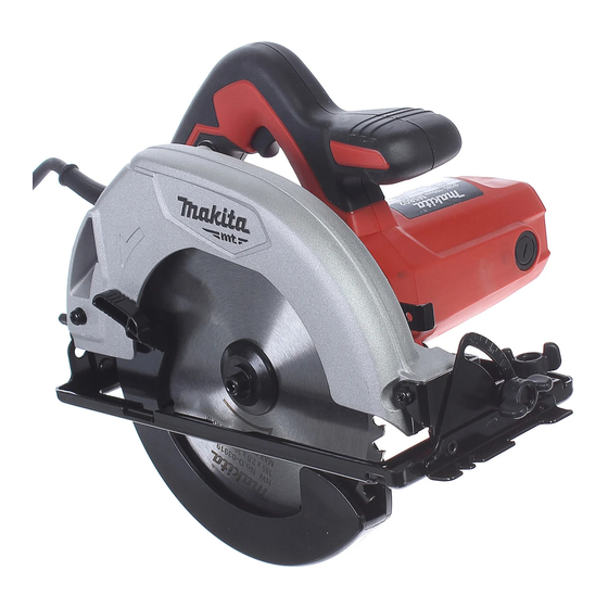
M5802
185(7-1/4")mm / 190(7-1/2") Circular Saw
Models M5802 is 185mm (7-1/4") Circular Saw and has been developed as
Makita-mt-series.
Its main features are:
·
New appearance; Features the same design concept as maktec/SSP-Makita brand
series; however, the logo has been replaced by "Makita-mt-" for new series
development.
·
Orange housing
·
Industrial performance and durability at less expense
·
Ergonomically designed handle with Soft grip
·
In compliance with the regulations of the EC directives
Voltage (V)
Current (A)
110
120
220
230
240
Specification
Type
Number of teeth
Saw
Diameter mm (")
blade
Hole diameter mm (")
Continuous rating input
Bevel angle : degree
Maximum
0 degrees mm
cutting capacity
45 degrees mm
Power supply cord : m (ft)
Dimensions (L x W x H) mm(")
Weight according to
EPTA-Procedure 01/ ver.2.1: kg(lbs)*4
*1 12 for European countries, 24 for Gulf countries, 40 for Asian countries
*2 190mm for European and Gulf countries, 185mm (7-1/4") for Asian countries
*3 30mm for European countries, 20mm for Gulf and Asian countries
*4 Weight with Dust nozzle and TCT saw blade
Guide rule ............................... 1 pc
Hex wrench 5 .......................... 1 pc
Dust nozzle .............................. 1 pc (for European countries only)
TCT saw blade ........................ 1 pc
Note: The standard equipment may vary by country or model variation.
Dust nozzle with M5x 14WR P.H.screw................ 1 pc
Cycle (Hz)
10
50/60
8.5
50/60
5.0
50/60
4.8
50/60
4.6
50/60
Model
(W)
(°)
(")
68(2-11/16")/66(2-5/8")
(")
46(1-13/16")/44(1-3/4")
H
Continuous Rating (W)
Input
1,050
----
1,050
1,050
1,050
Makita-mt-
M5802
TCT saw blade
12 *
1
185 (7-1/4) *
2
30 (1-3/16) *
3
1,050
0-45
2.0(6.6ft)
297x232x255
(11-3/4" x9-1/8" x10 ")
4.0(8.8lbs)
2
1 / 1
March 2016
W
L
Dimensions: mm (")
Length (L)
297 (11-3/4)
232 (9-1/8)
Width (W)
132 (5-3/16)
Height (H)
255 (10)
Max Output (W)
Output
650
1,300
570
1,300
650
1,300
650
1,300
650
1,300
P1/ 8
Advertisement

Related Manuals for Makita M5802


Summary of Contents for Makita M5802
- Page 1 March 2016 M5802 185(7-1/4”)mm / 190(7-1/2”) Circular Saw Models M5802 is 185mm (7-1/4") Circular Saw and has been developed as Makita-mt-series. Its main features are: · New appearance; Features the same design concept as maktec/SSP-Makita brand series; however, the logo has been replaced by “Makita-mt-” for new series development.
-
Page 2: Necessary Repairing Tools
Removing / Assembling Bearing retainer 19-33 [2] LUBRICATION Apply the following kinds of lubricant to the parts. Makita grease FA. No.2 to the parts designated with black triangle to protect parts and product from unusual abrasion. Symbol of Item No. - Page 3 P 3 / 12 epair [3] DISASSEMBLY/ASSEMBLY [3] -1. Base DISASSEMBLING (1) Remove saw blade in accordance with the instruction manual. First, remove M8x24 Flat headsquare neck bolt on Depth guide side, as shown in Fig. 2. Depth guide Angular plate Angular plate side Depth guide side Fig.
- Page 4 P 4 / 12 epair [3] DISASSEMBLY/ASSEMBLY [3] -1. Base DISASSEMBLING (2) Remove M5 Pan head screw on Angular plate side as shown in Fig. 3. Depth guide Angular plate Angular plate side Depth guide side Fig.3 1. Fixing M5 Hex nut with Wrench 8, 2.
- Page 5 P 5 / 12 epair [3] DISASSEMBLY/ASSEMBLY [3] -1. Base ASSEMBLING (1) Assemble Base by taking reverse step of Disassembling. Refer to Fig. 4, Fig. 3, Fig. 2. < Note > Pay attention to the matters in Fig. 5, when assembling Base. Fig.5 1.
- Page 6 P 6 / 12 epair [3] DISASSEMBLY/ASSEMBLY [3] -2-a Armature DISASSEMBLING (2) Remove Ball bearings from the Armature as shown in Fig. 7. Fig. 7 1. The space between Ball bearing 608ZZ and Insulation washer 2. Remove Ball bearing 6000ZZ with is too tight to engage the claw of 1R269.
-
Page 7: Safety Cover
P 7 / 12 epair [3] DISASSEMBLY/ASSEMBLY [3] -2-b Safety cover ASSEMBLING Assemble Safety cover as shown in Fig. 9. Fig. 9 3. Pass the another hook of Tension 2. Pass the hook of Tension spring 3 1. Make sure, that Thickness spring 3 thruogh the hole of Blade through the hole of Safety cover, ring is mounted to Bearing... - Page 8 P 8 / 12 epair [3] DISASSEMBLY/ASSEMBLY [3] -2-c Blade case complete ASSEMBLING (1) Assemble Bearing box to Blade case complete. Refer to right illustration in Fig. 10. (2) Assemble Compression spring 5 and Shaft lock to Blade case complete. And then, assemble Armature assembly to Blade case complete.
- Page 9 P 9 / 12 epair [3] DISASSEMBLY/ASSEMBLY [3] -3 Bearing box, Gear section DISASSEMBLING (4) Remove Ball bearing 6201ZZ as shown in Fig. 13R. Fig. 13R Straight flanged portion < Note > Hold Bearing box at its straight flanged portion, for keeping stabilized condition, when repair work.
- Page 10 P 10 / 12 epair [3] DISASSEMBLY/ASSEMBLY [3]-4. Adjustment of Lever plate ADJUSTMENBT Adjust Lever plate so that cut depth, desired by user, can be set at the position shown in the photograph below. See Fig. 15. Fig. 15 30 degrees Lever plate...
-
Page 11: Circuit Diagram
P 11 / 12 ircuit diagram Fig. D-1 Color index of lead wires' sheath Symbol of electrical parts Item No. Black Insulated terminal (M3.5) Blue Brown Spring terminal White < Note > AWG: American Wire Gage Switch AWG 18 AWG 18 Field AWG 18 AWG 20... -
Page 12: Wiring Diagram
P 12 / 12 iring diagram Fig. D-2 Wiring in Motor housing complete Switch Noise suppressor Motor housing complete Groove Power supply cord Lead wire Lead wire Groove holder (B) holder (A) Field lead wire Put sag of the Field lead Pass Field lead wires through grooves, wires to the space between Put Field lead wires to...