Makita PM7651H Technical Information
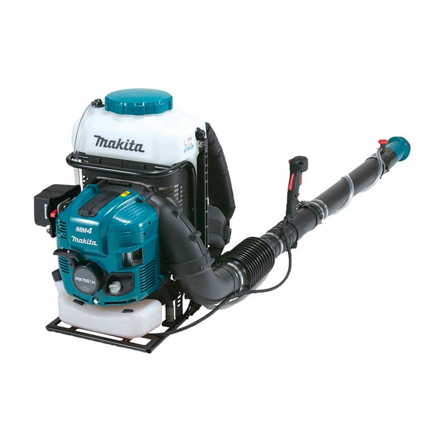
Petrol mist blower
Hide thumbs
Also See for PM7651H:
- Original instruction manual (272 pages) ,
- Instruction manual (220 pages) ,
- Original instruction manual (84 pages)
Advertisement
Quick Links
T
ECHNICAL INFORMATION
Model No.
Description
C
ONCEPT AND MAIN APPLICATIONS
Model PM7651H is a Petrol mist blower powered by 75.6mL
4-stroke engine, and developed based on the current model PM7650H.
The modifications from the current model PM7650H are as follows:
● Compliance with EU standards
• Lock-off button on the handle
• Without lock-on function for throttle
• Non-removable tank cap with retaining strap
• Gap between strainer and tank is 2mm or less
● Throttle lever with 3-stage switching function
● Anti-static throttle lever
S
pecification
Specification
Type
Displacement: mL (cu.in.)
Engine
Fuel
Max output: kW (PS)
Max torque: N·m
Max rotation speed at no load: min -ı = rpm
Engine oil
Compliance with exhaust emission regulations
Carburetor
Easy start
(Spring-assisted recoil starter)
Starting system
Decompression
Spark plug
Primer pump
Fuel tank capacity: L (US oz)
Solution tank capacity: L (US oz)
Max spray range (horizontal):
Max air speed: m/s
Max air volume*
:
m³/min
2
Rotation limiter
Dry weight*
: kg (lbs)
3
*1 "Straight" means "not mixed with engine oil".
*2 With nozzle
*3 With Straight pipe 380, without Hip belt
PM7651H
Petrol Mist Blower
Model
m (ft)
H
Straight unleaded gasoline*
2.7 (3.7) at 7,000 rpm
4.4 at 5,000 rpm
SAE10W-30 oil,
Class SF or higher of API Classification
Yes (Mechanical)
1 / 41
OFFICIAL USE
for ASC & Sales Shop
March 2016
W
Dimensions: mm (")
Length (L)
420 (16-1/2)
Width (W)
440 (17-1/4)
Height (H)
595 (23-1/2)
PM7651H
4-stroke
75.6 (4.61)
(E0 to E10)
1
7,400
Yes
Diaphragm
No
CMR6A
Yes
1.8 (61)
15.0 (507)
16.0 (52)
85
14.1 (497)
Yes
14.1 (31.1)
L
Advertisement

Related Manuals for Makita PM7651H


Summary of Contents for Makita PM7651H
- Page 1 Petrol Mist Blower Description ONCEPT AND MAIN APPLICATIONS Model PM7651H is a Petrol mist blower powered by 75.6mL 4-stroke engine, and developed based on the current model PM7650H. The modifications from the current model PM7650H are as follows: ● Compliance with EU standards •...
-
Page 2: Standard Equipment
OFFICIAL USE for ASC & Sales Shop tandard equipment Oil bottle* Hip belt set* Flat pipe* Box wrench Straight pipe 630* Nozzle 0.8* Hand strap Straight pipe 380* Tube 10-500* Flexible pipe Bent pipe 630* Hose clamp 76 (x4) End pipe 200* Hose clamp 100 (x1) End pipe 450* *1 With engine oil contained for some countries... - Page 3 INDEX INDEX ......................................3 CAUTION ....................................5 HANDLING OF GASKET ................................5 NECESSARY REPAIRING TOOLS ............................5 LUBRICANT AND ADHESIVE APPLICATION ........................6 Several sections ..................................6 Cylinder block section ................................7 REPAIR ......................................8 Nozzle section ..................................8 6-1-1 Disassembling ................................
- Page 4 6-15 Engine block ..................................37 6-15-1 Cylinder head section ..............................37 6-15-2 Adjustment of valve clearance ..........................39 6-15-3 Assembling of Muffler exhaust and Insulator complete .................... 39 6-16 Final check ..................................40 TIGHTENING TORQUE SPECIFICATIONS .......................... 41 4 / 41...
-
Page 5: Necessary Repairing Tools
CAUTION Repair the machine in accordance with “Instruction manual” or “Safety instructions. Follow the instructions described below in advance before repairing: Wear gloves. · When the engine is hot from use, cool down the engine enough or you can get burned. ·... -
Page 6: Lubricant And Adhesive Application
LUBRICANT AND ADHESIVE APPLICATION Apply the following lubricants and adhesives. Several sections Lubricant Amount Makita grease FA No.2 a little 4-stroke engine oil a little Fig. 5-1-1 Fig. 5-1-2 Spiral spring Outer circumference of O ring 93 Elbow Fig. 5-1-3 Fig. - Page 7 Cylinder block section Use parts cleaner or the like to remove grease from the mating surface of Crankcase to Cylinder block, and then apply ThreeBond 1215 or 1216 as shown below. Fig. 5-2-1 Oil route Note: ThreeBond 1215 or 1216 should not be come into here.
- Page 8 Tube 10-500 or Tube 10-250 Hose clamp 14 Top adapter Diffusion cover Nozzle adapter complete Hose clamp Apply Makita grease FA M5x18 Pan head screw Straight pipe No.2. Fig. 6-1-1-2 Fig. 6-1-1-3 [4] Remove 4x20 Tapping screw, and remove Sleeve 25 [5] Remove O ring 28 from Sleeve 25.
- Page 9 Cock section 6-2-1 Disassembling Fig. 6-2-1-1 [1] Release two Hose clamps 76, and remove Cock body and Strainer case. Strainer case Cock body Front side Hose clamp 76 (2 pcs.) Fig. 6-2-1-2 [2] The components of Cock section are as follows: Tube 10-500 Hose clamp 14 Tube 10-750...
- Page 10 [1] Assemble by reversing the disassembly procedure. Fig. 6-2-2-1 Fig. 6-2-2-2 [2] Apply Makita grease FA No.2 a little on the [3] Insert Cock into Cock body and turn it with pliers as shown below, outer circumference of Cock and O-ring 9.
- Page 11 Pipe section 6-3-1 Disassembling Fig. 6-3-1-1 [1] Overall view of Pipe section is as follows: Fig. 6-3-1-5 Fig. 6-3-1-2 Fig. 6-3-1-3, Fig. 6-3-1-4 Fig. 6-3-1-2 Fig. 6-3-1-3 [2] Disconnect Tube 10-750. [4] Release Hose clamp 76, and remove Swivel pipe [3] Release Hose clamp 76, and remove Straight pipe by complete and Flexible pipe complete.
- Page 12 Engine cover complete, Recoil, Fuel tank 6-4-1 Disassembling Fig. 6-4-1-1 [1] Remove three M5x20 Pan head screws, and remove Recoil. Recoil M5x20 Pan head screw (3 pcs.) Fig. 6-4-1-2 [2] Remove four 5x20 Tapping screws, and remove Engine cover complete. 5x20 Tapping screw (4 pcs.) Engine cover...
- Page 13 Fig. 6-4-1-3 [3] Remove the fuel tubes of Tube assembly from Carburetor and Primer pump. (Fig. 6-4-1-4) [4] Remove three M6x12 Pan head screws, and remove Fuel Tank. (Fig. 6-4-1-5) Fig. 6-4-1-6 Breather pipe Fig. 6-4-1-4 Carburetor Primer pump Tube assembly Fuel tank Transparent blue Black fuel tube of...
- Page 14 Control cable 6-5-1 Disassembling Fig. 6-5-1-1 [1] Cut and remove Wire band with cutting pliers. Wire band [2] Remove Control cable and ON/OFF switch cords from the hook of Volute case 2, then disconnect the bullet terminal of ON/OFF switch cords. (Fig. 6-5-1-2) [3] Remove Control cable and the high voltage cable of Ignition coil from the wire holder of Volute case 2.
- Page 15 Tank complete (Chemical tank) 6-6-1 Disassembling Fig. 6-6-1-1 [1] Remove Hose clamp 14, and remove Tube 10-750 from Joint strainer. Joint strainer Hose clamp 14 Tube 10-750 Fig. 6-6-1-2 Fig. 6-6-1-3 [2] Remove Hose clamp 14, and remove Tube 10-300 from [3] Remove four E-4 Stop rings with small pliers and pull Pressure pipe.
- Page 16 [7] Remove Hose clamp 14, and remove Sponge 12 by disconnecting Tube 10-300 from Joint 1. (Fig. 6-6-1-5) [8] Remove Strap by removing Joint 1 and Grommet from the top of Tank complete. (Fig. 6-6-1-5 and Fig. 6-6-1-6) [9] Remove Hose clamp 14, and remove Tube 10-500 from Joint 1 and Mixing body upper. (Fig. 6-6-1-6 and Fig. 6-6-1-7) [10] Remove two M5x12 Pan head screws, and remove Mixing body upper from Mixing body lower.
- Page 17 Blower section 6-7-1 Disassembling Fig. 6-7-1-1 [1] Remove two M6x20 Pan head screws, and remove Frame complete. [2] Remove Lower frame holder and Compression spring 17 from Frame holder. Frame complete Frame holder Lower frame holder Compression M6x20 Pan head spring 17 screw (2 pcs.) Fig.
- Page 18 [8] Remove 4x18 Tapping screw, and remove Pressure pipe from Volute case 1. Note: Be sure not to lose Flat washer 4. 4x18 Tapping screw O ring 93 Apply Makita grease FA No.2. Pressure pipe Elbow Flat Washer 4 Volute case 1 Fig.
- Page 19 Frame section 6-8-1 Disassembling Fig. 6-8-1-1 Remove six M4x25 Pan head screws, and remove Guard from Frame complete. Frame complete M4x25 Pan head screw (6 pcs.) Guard 6-8-2 Assembling Assemble by reversing the disassembly procedure. 19 / 41...
- Page 20 Ignition system 6-9-1 Checking plug cap [1] Remove Plug cap from Spark plug, then check the continuity between Plug cap spring and the ground (earth) terminal of Ignition coil with 1R402-A. (Fig. 6-9-1-1) [2] If there is no or intermittent continuity, check the continuity between Ignition cable and Plug cap spring by following the steps described below.
- Page 21 6-9-3 Checking of Ignition coil For checking troubles in Ignition System of Gasoline engines. Set it between Plug cap and Plug to check the state of ignition. Note: Do not remove Spark plug. · It is necessary to check the sparks generate certainly by pulling Starter rope against the compressed air in Cylinder for normal ·...
- Page 22 6-9-4 Checking of Ignition coil (cont.) Next, check the behavior during engine’s run as the following order. Fig. 6-9-4-1 Purpose: Clarify the cause of stall and poor acceleration resulting from; vanishment of sparks or the other reasons. [1] Attach Alligator clip to Spark [2] Turn Spark distance adjusting knob so that the spark plug.
- Page 23 6-9-5 Removing Ignition coil Fig. 6-9-5-1 Remove Wire (primary wire) from Ignition coil, then remove Ignition coil from the engine by loosening two M4x20 Socket head bolts. Ignition coil Wire (primary wire) M4x20 Socket head bolt (2 pcs.) 6-9-6 Mounting Ignition coil Fig.
- Page 24 6-9-7 Removing Flywheel complete WARNING!! Before starting removal procedure, be sure to remove Plug cap from Spark plug to prevent accidental engine start. Fig. 6-9-7-1 Fig. 6-9-7-2 [1] Remove M10 Flange nut by turning it counterclockwise [2] Mount Flywheel puller (1R364) on Flywheel complete with an impact driver equipped with a hex socket bit 14.
- Page 25 Note: Keeping eye on the hook so that the spring isn’t loosened, hold and slide the spring with both thumbs. [2] Apply a little amount of Makita grease FA No.2 to the whole surface of Spiral spring. [3] Put a new Starter rope through Starter case complete.
- Page 26 Fig. 6-10-2-4 Fig. 6-10-2-5 [5] While turning Reel counterclockwise, mount it in Starter case [6] Set Collar and two Swing arms in place on Reel. complete. Then hook the inner end of Spiral spring in the slit of Be sure to insert each Swing arm through the the shaft portion of Starter case complete.
- Page 27 6-11 Carburetor section 6-11-1 Removing Carburetor [1] Remove Air cleaner cover complete from Air cleaner plate by loosening M5x25 Pan head screw. (Fig. 6-11-1-1) [2] Remove Air cleaner element. (Fig. 6-11-1-2) [3] Remove two M5x70 Pan head screws that fasten Air cleaner plate and Carburetor to Cylinder head complete. Note: Completely remove the two screws from Air cleaner plate or Carburetor cannot be removed from Cylinder head complete.
- Page 28 [4] Before mounting the inner parts of Pump body assembly in place, make sure that the tip of Inlet needle is neither worn nor deformed. (Fig. 6-11-2-2) Note: The inner parts are not available individually. If you need some of the inner parts, order Pump body assembly. [5] When mounting Control lever, make sure that the upper end of Spring is firmly held in place under the projection of Control lever.
- Page 29 6-11-3 Assembling Carburetor Assemble by reversing the disassembly procedure. Note: Make sure that the assembling direction of each part is correct. 6-11-4 Vacuum leak test of Carburetor Fig. 6-11-4-1 Connect 1R127 with the fuel inlet of Carburetor, then increase the testing pressure up to 0.05Mpa. The pressure will stay the same about 10 seconds if there is no vacuum leak.
- Page 30 Fig. 6-11-5-4 [4] Mount Air cleaner element onto Air cleaner plate. [5] Mount Air cleaner cover complete onto Air cleaner plate, then secure with M5x25 Pan head screw. Note: For secure mounting, be sure to fit the locking tab of Air cleaner plate into the slot of Air cleaner cover complete. Locking tab Air cleaner plate Air cleaner element...
- Page 31 6-12 Stop switch 6-12-1 Checking Stop switch Fig. 6-12-1-1 Check the continuity between the bullet terminals on the two lead wires extending from Control lever with 1R402-A. If Stop switch functions properly, there will be no continuity with the switch ON and there will be continuity with the switch OFF. Control lever 1R402 6-13...
- Page 32 6-14 Engine block 6-14-1 Engine block section 6-14-1-1 Disassembling [1] It is highly recommended to drain the oil system of Engine block before starting disassembling because the remaining oil will spill out. [2] Remove Engine section from Volute case. (See 6-7 Blower section.) [3] Remove Ignition coil, Flywheel and Spark plug from Engine section.
- Page 33 Fig. 6-14-1-1-4 Fig. 6-14-1-1-5 [8] Remove Cam gear cover, and remove Pin 5, Cam lifter [9] Remove five M5x25 Hex socket head bolts, and remove and Camgear assy. Oil case from Cylinder block set. Note: Assemble Cam lifters in the correct direction. Oil case Cam lifter R Note: There is a cross...
- Page 34 Fig. 6-14-1-1-9 Fig. 6-14-1-1-10 [13] Remove two Ring springs 12 from the ends of Piston [14] Push out Piston pin with 1R286, and remove Piston. pin with a pointed tool such as an awl. Piston pin Ring spring 12 Note: Be careful that Ring spring 12 pops out.
- Page 35 Fig. 6-14-1-2-2 [5] Assemble Cylinder block set. Use parts cleaner or the like to remove grease from the mating surface of Crankcase to Cylinder block, and then apply ThreeBond 1215 or 1216 as shown below. Oil route Note: ThreeBond 1215 or 1216 should not be come into here.
- Page 36 Fig. 6-14-1-2-5 Fig. 6-14-1-2-6 [8] Assemble Oil case gasket, Lead valve and Retainer plate with [9] Bend Oil tube to the lead valve side. M4x10 Socket head bolt. Note: Do not reuse removed Oil case gasket. Replace it with a new one.
- Page 37 6-15 Engine block 6-15-1 Cylinder head section 6-15-1-1 Disassembling Fig. 6-15-1-1-1 Remove Cotter from Cylinder head complete using 1R005 and 1R389, and remove two Retainers, Compression springs 11, Intake valve and Exhaust valve. Remove Cotter with a slotted screwdriver magnetized with 1R288. 1R389 1R005 Cotter...
- Page 38 Fig. 6-15-1-2-2 Fig. 6-15-1-2-3 [3] Set Flywheel with M10 Flange nut [4] Turn Flywheel by hand to align each marking on Flywheel temporarily. parallel to Crankcase. Piston comes to the upper dead point in Cylinder block set. M10 Flange nut Flywheel Marking Oil case...
- Page 39 6-15-2 Adjustment of valve clearance Adjust the valve clearance as follows: [1] Align each marking on Flywheel parallel to Crankcase. (Fig. 6-15-1-2-3) Fig. 6-15-2-1 Fig. 6-15-2-2 [2] Loosen Adjusting screws, and insert 0.1mm feeler [4] Assemble Rocker cover gasket and Rocker cover gauge of 1R366 into the clearance between Rocker arms complete to Cylinder head complete with two M5x30 and Intake/ exhaust valve holes.
- Page 40 6-16 Final check Be sure to check the following points. Tighten each bolt/screw to the specific torque without failure. · Contain Regular gasoline in Fuel tank. · Contain 4 cycle engine oil in Oil tank. · Push Primer pump several times to feed the fuel into Carburetor, and then pull Starter knob to start the ignition. ·...
-
Page 41: Tightening Torque Specifications
TIGHTENING TORQUE SPECIFICATIONS *W: Spring washer R: Flat washer M: Thread locking patch Tightening torque Parts to fasten Fastener Q’ty (N・m) Crankcase Cylinder M6x30 Hex socket head bolt 10.0 - 12.0 Retainer plate Crankcase M4x10 Socket head bolt with W 2.0 - 3.5 ...