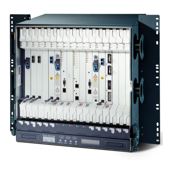
Cisco ONS 15454 Unpacking And Installing
Four-shelf and zero-shelf bay assembly
Hide thumbs
Also See for ONS 15454:
- Hardware installation manual (516 pages) ,
- Troubleshooting manual (107 pages) ,
- Manual (88 pages)
Advertisement
Quick Links
Unpacking and Installing the Cisco ONS 15454
Four-Shelf and Zero-Shelf Bay Assembly
Overview
The Cisco ONS 15454 Four-Shelf and Zero-Shelf Bay Assemblies provide a dual-feed pre-wired
TPA-type Fuse and Alarm Panel, two vertical fiber ducts, and two 2.38-inch vertical extenders and
extender bases. The Four-Shelf Bay Assembly also provides a pre-installed, four-shelf configuration that
includes four ONS 15454 shelf assemblies with configured backplane interface connectors (BICs).
This guide describes how to unpack and install the Cisco ONS 15454 Four-Shelf and Zero-Shelf Bay
Assembly. Because it is a complete system, installation simply requires you to remove the unit from the
shipping pallet, move the unit into place, secure it, supply power and ground attachment.
This guide includes the following sections:
•
•
•
•
•
•
•
•
Corporate Headquarters:
Cisco Systems, Inc., 170 West Tasman Drive, San Jose, CA 95134-1706 USA
Copyright © 2002. Cisco Systems, Inc. All rights reserved.
Safety Recommendations
Recommended Materials
Unpacking Instructions
Installation Instructions
Install the Four-Shelf and Zero-Shelf Bay Assembly
–
–
Slab Floor Plan
Raised Floor Plan
–
–
Mounting a Single Shelf Assembly
Mounting the Fuse and Alarm Panel
–
Cabling Illustrations
Fuse and Alarm Panel Wiring
Install the Power and Ground
Optional Kits
Advertisement

Related Manuals for Cisco ONS 15454


Summary of Contents for Cisco ONS 15454
- Page 1 ONS 15454 shelf assemblies with configured backplane interface connectors (BICs). This guide describes how to unpack and install the Cisco ONS 15454 Four-Shelf and Zero-Shelf Bay Assembly. Because it is a complete system, installation simply requires you to remove the unit from the shipping pallet, move the unit into place, secure it, supply power and ground attachment.
-
Page 2: Safety Recommendations
3/4 in. (19 mm) socket or box-end wrench for the earthquake floor bolts • Four optional kits listed in Table 2 on page 33 that can be ordered separately Unpacking and Installing the Cisco ONS 15454 Four-Shelf and Zero-Shelf Bay Assembly 78-13271-05... - Page 3 An AC outlet is provided on the front of the base if 110VAC powering is needed. Wiring for AC power must be performed by an electrician. The AC outlet at the base of the shelf should be protected by a 20A breaker maximum. Caution Unpacking and Installing the Cisco ONS 15454 Four-Shelf and Zero-Shelf Bay Assembly 78-13271-05...
- Page 4 Recommended Materials Figure 2 Rack assembly Unpacking and Installing the Cisco ONS 15454 Four-Shelf and Zero-Shelf Bay Assembly 78-13271-05...
-
Page 5: Unpacking Instructions
Unpacking Instructions Unpacking Instructions The ONS 15454 Four-Shelf and Zero-Self Bay Assembly ships in a corrugated container that covers the unit on its shipping pallet. After removing the corrugated container, you must remove the bolts that hold the rack to the pallet before moving the unit to the desired location. - Page 6 Unpacking Instructions Figure 3 Four-Shelf Bay Assembly on shipping pallet Unpacking and Installing the Cisco ONS 15454 Four-Shelf and Zero-Shelf Bay Assembly 78-13271-05...
-
Page 7: Installation Instructions
Install the Bay Assembly according to local site practice. Step 8 For more information about installing or configuring individual Cisco ONS 15454s, refer to Cisco ONS 15454 user documentation. After the rack is installed attach the extender bases and vertical extenders to both sides of the rack. - Page 8 (can require a larger gauge wire depending on distance) wire depending on distance) Rack ground Rack ground feed wire, #4 AWG feed wire, #4 AWG Figure 5 Slab base fiber routing Unpacking and Installing the Cisco ONS 15454 Four-Shelf and Zero-Shelf Bay Assembly 78-13271-05...
- Page 9 It will be necessary to use alternate anchoring holes in the event the primary holes are obstructed Note by the stringers that support the removable tile. Unpacking and Installing the Cisco ONS 15454 Four-Shelf and Zero-Shelf Bay Assembly 78-13271-05...
- Page 10 On the bottom of the u-channel, use the clip, washer, lockwasher, and nut. Note The u-channel should not extend more than four inches past the edge of the stringers or it will block access under the floor. Unpacking and Installing the Cisco ONS 15454 Four-Shelf and Zero-Shelf Bay Assembly 78-13271-05...
- Page 11 After installing the rack onto the raised floor, remove the base plate cover from the rack by removing Step 1 the screws on the front of the base plate, as shown in Figure Figure 7 Removing the base plate from the rack Unpacking and Installing the Cisco ONS 15454 Four-Shelf and Zero-Shelf Bay Assembly 78-13271-05...
- Page 12 Raised floor base fiber routing close-up You can use the base plate or extender base holes to route the fibers. Cisco recommends using the base plate holes for the bottom node and the extender base holes for the other three nodes on the four-node rack.
- Page 13 Mounting a Single Shelf Assembly Mounting a single ONS 15454 in a rack requires a minimum of 18.5 inches of vertical rack space (plus 1 inch for air flow). To ensure the mounting is secure, use two to four #12-24 mounting screws for each side of the shelf assembly.
- Page 14 Install one mounting screw in each side of the shelf assembly. Step 6 One or more sets of the horizontal screw slots on the ONS 15454 should be used to prevent future slippage. When the shelf assembly is secured to the rack, install the remaining mounting screws.
- Page 15 Step 4 in each side of the assembly. One or more sets of the horizontal screw slots on the ONS 15454 should be used to prevent future slippage. When the shelf assembly is secured to the rack, install the remaining mounting screws.
- Page 16 Cabling Illustrations Cabling Illustrations Figure 13 A fiber guide on a four-node rack Fiber Guide Unpacking and Installing the Cisco ONS 15454 Four-Shelf and Zero-Shelf Bay Assembly 78-13271-05...
- Page 17 Cabling Illustrations Figure 14 Rear view of a four-node rack Ground #4AWG wire to attach to ground feed Power cable Ground strap #6AWG Alarm cables Unpacking and Installing the Cisco ONS 15454 Four-Shelf and Zero-Shelf Bay Assembly 78-13271-05...
- Page 18 Cabling Illustrations Figure 15 Side view of DS1 and power cables Power cables DS1 cables Figure 16 DS1 cable close-up of lacing DS1 cables Power cables Unpacking and Installing the Cisco ONS 15454 Four-Shelf and Zero-Shelf Bay Assembly 78-13271-05...
- Page 19 Cabling Illustrations Figure 17 Side rack view of DS1 and power cables Power cables DS1 cables Unpacking and Installing the Cisco ONS 15454 Four-Shelf and Zero-Shelf Bay Assembly 78-13271-05...
- Page 20 Cabling Illustrations Figure 18 Cabling on one node DS-1 cables Base of rack DS-3 cables Unpacking and Installing the Cisco ONS 15454 Four-Shelf and Zero-Shelf Bay Assembly 78-13271-05...
- Page 21 Cabling Illustrations Figure 19 Standoff with wiring Timing cables DS-3 cables Fiber guide Unpacking and Installing the Cisco ONS 15454 Four-Shelf and Zero-Shelf Bay Assembly 78-13271-05...
- Page 22 Cabling Illustrations Figure 20 Standoff at bottom of rack Timing cables Alarming cable DS-3 cables Unpacking and Installing the Cisco ONS 15454 Four-Shelf and Zero-Shelf Bay Assembly 78-13271-05...
- Page 23 The FAP included in the four-shelf and zero-shelf bay assemblies has the capability to report eight alarms to a network operations center (NOC). The ONS 15454 has the capability to report four environmental alarms through the system. Only one shelf (with an AIC/AIC-I card) is needed to monitor alarming for a loss of power and a blown fuse condition.
- Page 24 FAP and power The Cisco ONS 15454 bay assemblies use 4-pair, CAT 3-rated, twisted pair wire for FAP wiring. To achieve all of the alarming capabilities of the FAP the wiring is doubled on the pins of the alarm cards.
- Page 25 3.4.0. In this case the backplane pin labeling will appear as indicated in Figure 25. But you must use the pin assignments provided by the AIC-I as shown in Figure Unpacking and Installing the Cisco ONS 15454 Four-Shelf and Zero-Shelf Bay Assembly 78-13271-05...
- Page 26 Alarm input pair number 10: Reports closure on connected wires. Alarm input pair number 11: Reports closure on connected wires. Alarm input pair number 12: Reports closure on connected wires. Unpacking and Installing the Cisco ONS 15454 Four-Shelf and Zero-Shelf Bay Assembly 78-13271-05...
- Page 27 (such as copper and aluminum, or copper and copper-clad aluminum), unless the device is suited for the purpose and conditions of use. Connect the ONS 15454 only to a DC power source that complies with the safety extra-low voltage Warning (SELV) requirements in IEC 60950-based safety standards.
- Page 28 Figure 26 Ground location on the backplane FRAME GROUND Attach #6 AWG Attach the other end of the shelf ground cable to the bay (Figure 27). Step 4 Unpacking and Installing the Cisco ONS 15454 Four-Shelf and Zero-Shelf Bay Assembly 78-13271-05...
- Page 29 View of the power from the BDFB/power breaker panel to LVD connection BDFB cables Connect Office Power to the ONS 15454 Shelf Tools needed: • H-tap • H-tap crimp tool Unpacking and Installing the Cisco ONS 15454 Four-Shelf and Zero-Shelf Bay Assembly 78-13271-05...
- Page 30 -48 VDC and return. Note If the system loses power or both TCC+ cards are reset, you must reset the ONS 15454 clock. After powering down, the date defaults to January 1, 1970, 00:04:15. Refer to Cisco ONS 15454 user documentation for information about resetting the ONS 15454 clock.
- Page 31 PLEASE REFER TO INSTALLATION INSTRUCTIONS. Remove or loosen the #8 power terminal screws on the ONS 15454. To avoid confusion, label the cables Step 4 connected to the BAT1/RET1 (A) power terminals as 1, and the cables connected to the BAT2/RET2 (B) power terminals as 2.
- Page 32 10 in-lbs. When terminating a frame ground, use the kep-nut provided with the ONS 15454 and tighten it to a torque specification of 31 in-lbs. The kep-nut provides a frame ground connection that minimizes the possibility of loosening caused by rotation during installation and maintenance activity.
-
Page 33: Optional Kits
15454 Bay Extender Kit (2.38-inch) 74-2794-01 15454-BAY-COVER= 15454 Bay End Plate Cover Kit 74-2795-01 15454-BAY-GUARD= 15454 Bay End Guard Kit 74-2796-01 15454-BAY-ACC1= 15454 First Aid Kit 53-2073-01 Unpacking and Installing the Cisco ONS 15454 Four-Shelf and Zero-Shelf Bay Assembly 78-13271-05... - Page 34 The 15454 Bay Extender Kit provides rear cable protection, additional cable management space and includes a 2.38-inch vertical extender (Figure 30) and extender base (Figure 31 Figure 32). Figure 30 Vertical extender Figure 31 Extender base Unpacking and Installing the Cisco ONS 15454 Four-Shelf and Zero-Shelf Bay Assembly 78-13271-05...
- Page 35 Optional Kits Figure 32 Extender base assembly Unpacking and Installing the Cisco ONS 15454 Four-Shelf and Zero-Shelf Bay Assembly 78-13271-05...
- Page 36 The end plate cover can be mounted with the 2.38-inch extender as shown in Figure 33 or mounted directly as shown in Figure Figure 33 End plate cover assembly mounted with 2.38-inch extender End plate Extender Unpacking and Installing the Cisco ONS 15454 Four-Shelf and Zero-Shelf Bay Assembly 78-13271-05...
- Page 37 Optional Kits Figure 34 End plate cover assembly mounted directly Unpacking and Installing the Cisco ONS 15454 Four-Shelf and Zero-Shelf Bay Assembly 78-13271-05...
- Page 38 The 15454 First Aid Kit contains extra items such as, tape, cord, tags, and fuses; and cosmetic items such as, touch-up paint to promote a quality installation. Unpacking and Installing the Cisco ONS 15454 Four-Shelf and Zero-Shelf Bay Assembly 78-13271-05...
- Page 39 Optional Kits Unpacking and Installing the Cisco ONS 15454 Four-Shelf and Zero-Shelf Bay Assembly 78-13271-05...
- Page 40 Optional Kits Unpacking and Installing the Cisco ONS 15454 Four-Shelf and Zero-Shelf Bay Assembly 78-13271-05...
- Page 41 This document is to be used in conjunction with Cisco ONS 15454 user documentation. CCVP, the Cisco logo, and Welcome to the Human Network are trademarks of Cisco Systems, Inc.; Changing the Way We Work, Live, Play, and Learn is a service mark of Cisco Systems, Inc.;...
- Page 42 Optional Kits Unpacking and Installing the Cisco ONS 15454 Four-Shelf and Zero-Shelf Bay Assembly 78-13271-05...