Cisco ONS 15454 Unpacking And Installing
Four-shelf and zero-shelf bay assembly
Hide thumbs
Also See for ONS 15454:
- Hardware installation manual (516 pages) ,
- Troubleshooting manual (107 pages) ,
- Manual (88 pages)
Advertisement
Quick Links
Unpacking and Installing the Cisco ONS 15454
Four-Shelf and Zero-Shelf Bay Assembly
Cisco ONS 15454 Four-Shelf and Zero-Shelf Bay Assembly
Overview
The Cisco ONS 15454 four-shelf and zero-shelf bay assemblies provide a dual-feed, pre-wired TPA-type
fuse and alarm panel, two vertical fiber ducts, and two 2.38-inch vertical extenders and extender bases.
The four-shelf bay assembly also provides a pre-installed, four-shelf configuration that includes four
ONS 15454 shelf assemblies with electrical interface assembly (EIA) panels or EIA blank cover panels.
This guide describes how to unpack and install the Cisco ONS 15454 four-shelf and zero-shelf bay
assembly. Because it is a complete system, installation simply requires you to remove the unit from the
shipping pallet, move the unit into place, secure it, and supply power and ground attachment. Refer to
the Cisco ONS 15454 user documentation for component-specific installation and replacement
procedures.
This guide includes the following sections:
•
•
•
•
•
•
•
Corporate Headquarters:
Cisco Systems, Inc., 170 West Tasman Drive, San Jose, CA 95134-1706 USA
Copyright © 2004 Cisco Systems, Inc. All rights reserved.
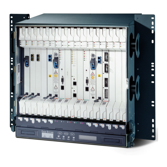
Figure 1 on page 2
Safety Recommendations
Included Material
Recommended Material
Unpacking Instructions
Installation Instructions
–
Slab Floor Plan
Raised Floor Plan
–
–
Install the ONS 15454 Four-Shelf or Zero-Shelf Bay Assembly
Route Fiber Through the Base
–
Cabling Illustrations
Fuse and Alarm Panel Wiring
–
FAP Alarming
FAP Output and Input Power
–
shows a four-shelf bay assembly.
Advertisement

Related Manuals for Cisco ONS 15454


Summary of Contents for Cisco ONS 15454
- Page 1 ONS 15454 shelf assemblies with electrical interface assembly (EIA) panels or EIA blank cover panels. This guide describes how to unpack and install the Cisco ONS 15454 four-shelf and zero-shelf bay assembly. Because it is a complete system, installation simply requires you to remove the unit from the shipping pallet, move the unit into place, secure it, and supply power and ground attachment.
- Page 2 An AC outlet is provided on the front of the base if 110VAC powering is needed. Wiring for AC power Note must be performed by an electrician. Unpacking and Installing the Cisco ONS 15454 Four-Shelf and Zero-Shelf Bay Assembly 78-15720-04...
- Page 3 Cisco ONS 15454 Four-Shelf and Zero-Shelf Bay Assembly Overview Figure 2 shows how the rack is assembled. Figure 2 Rack assembly Unpacking and Installing the Cisco ONS 15454 Four-Shelf and Zero-Shelf Bay Assembly 78-15720-04...
-
Page 4: Safety Recommendations
Plastic rear cover • Rear cover support • Right and left fiber channels • Phillips head custom screws • Touch up paint • Quick installation and configuration documentation • Unpacking and Installing the Cisco ONS 15454 Four-Shelf and Zero-Shelf Bay Assembly 78-15720-04... -
Page 5: Recommended Material
Cisco ONS 15454-FAP-LVD Operations Guide. Unpacking Instructions The ONS 15454 four-shelf and zero-self bay assembly ships in a corrugated container that covers the rack on its shipping pallet. After removing the corrugated container, you must remove the bolts that hold the rack to the pallet before moving the unit to the desired location. - Page 6 Stability hazard. The rack stabilizing mechanism must be in place, or the rack must be bolted to the floor before you slide the unit out for servicing. Failure to stabilize the rack can cause the rack to tip over. Unpacking and Installing the Cisco ONS 15454 Four-Shelf and Zero-Shelf Bay Assembly 78-15720-04...
-
Page 7: Installation Instructions
Relevel the rack using metal shims if necessary. Step 4 Install the bay assembly according to local site practice. Step 5 Unpacking and Installing the Cisco ONS 15454 Four-Shelf and Zero-Shelf Bay Assembly 78-15720-04... - Page 8 ONS 15454 node Extender base cover Extender base cover with screws with screws Extender base Extender base Base plate cover Base plate cover with screws with screws Base plate Unpacking and Installing the Cisco ONS 15454 Four-Shelf and Zero-Shelf Bay Assembly 78-15720-04...
- Page 9 It will be necessary to use alternate anchoring holes in the event the primary holes are obstructed Note by the stringers that support the removable tile. Unpacking and Installing the Cisco ONS 15454 Four-Shelf and Zero-Shelf Bay Assembly 78-15720-04...
- Page 10 On the bottom of the u-channel, use the clip, washer, lockwasher, and nut. Note The u-channel should not extend more than four inches past the edge of the stringers or it will block access under the floor. Unpacking and Installing the Cisco ONS 15454 Four-Shelf and Zero-Shelf Bay Assembly 78-15720-04...
- Page 11 Install the bay assembly according to local site practice. Step 7 After the rack is installed attach the extender bases and vertical extenders to both sides of the rack as needed. Unpacking and Installing the Cisco ONS 15454 Four-Shelf and Zero-Shelf Bay Assembly 78-15720-04...
- Page 12 Extender base cover with screws with screws Extender base Extender base Base plate cover Base plate cover with screws with screws Base plate (slid out from rack) Unpacking and Installing the Cisco ONS 15454 Four-Shelf and Zero-Shelf Bay Assembly 78-15720-04...
- Page 13 When the covers have been removed, you have access to the base of the rack and any holes previously cut into the raised floor tile, as shown in Figure Figure 9 Raised Floor Base Fiber Routing Close-up Unpacking and Installing the Cisco ONS 15454 Four-Shelf and Zero-Shelf Bay Assembly 78-15720-04...
- Page 14 Installation Instructions You can use the base plate or extender base holes to route the fibers. Cisco recommends using the base plate holes for the bottom node and the extender base holes for the other three nodes on the four-node rack.
- Page 15 Cabling Illustrations Cabling Illustrations Figure 11 through Figure 19 illustrate cabling schemes for a bay assembly. Figure 11 A Fiber Guide on a Four-Node Rack Fiber Guide Unpacking and Installing the Cisco ONS 15454 Four-Shelf and Zero-Shelf Bay Assembly 78-15720-04...
- Page 16 Cabling Illustrations Figure 12 Rear View of a Four-Node Rack Ground #4AWG wire to attach to ground feed Power cable Ground strap #6AWG Alarm cables Unpacking and Installing the Cisco ONS 15454 Four-Shelf and Zero-Shelf Bay Assembly 78-15720-04...
- Page 17 Cabling Illustrations Figure 13 Side View of DS1 and Power Cables Power cables DS1 cables Figure 14 Close-Up of Power Cable Lacing DS1 cables Power cables Unpacking and Installing the Cisco ONS 15454 Four-Shelf and Zero-Shelf Bay Assembly 78-15720-04...
- Page 18 Cabling Illustrations Figure 15 Side Rack View of DS1 and Power Cables Power cables DS1 cables Unpacking and Installing the Cisco ONS 15454 Four-Shelf and Zero-Shelf Bay Assembly 78-15720-04...
- Page 19 Cabling Illustrations Figure 16 Cabling on One Node DS-1 cables Base of rack DS-3 cables Unpacking and Installing the Cisco ONS 15454 Four-Shelf and Zero-Shelf Bay Assembly 78-15720-04...
- Page 20 Cabling Illustrations Figure 17 Standoff with Wiring Timing cables DS-3 cables Fiber guide Unpacking and Installing the Cisco ONS 15454 Four-Shelf and Zero-Shelf Bay Assembly 78-15720-04...
- Page 21 Cabling Illustrations Figure 18 Standoff at Bottom of Rack Timing cables Alarming cable DS-3 cables Unpacking and Installing the Cisco ONS 15454 Four-Shelf and Zero-Shelf Bay Assembly 78-15720-04...
- Page 22 Cabling Illustrations Figure 19 48 Fibers from One Node Unpacking and Installing the Cisco ONS 15454 Four-Shelf and Zero-Shelf Bay Assembly 78-15720-04...
- Page 23 The FAP included in the four-shelf and zero-shelf bay assemblies provides four sets of two 30A fused drops, for powering the redundant A and B inputs of four ONS 15454 nodes. The FAP has integrated low voltage disconnect (LVD) circuitry to provide a shutdown of the output power due to a drop in input voltage from the network power source.
- Page 24 1 A2 2 1 A1 2 MAX. INPUT 75A MAX. INPUT 75A 50A MAX. PER FUSE POS. 50A MAX. PER FUSE POS. MAX. INPUT 75A MAX. INPUT 75A Unpacking and Installing the Cisco ONS 15454 Four-Shelf and Zero-Shelf Bay Assembly 78-15720-04...
- Page 25 Fuse and Alarm Panel Wiring FAP Alarming The Cisco ONS 15454 bay assemblies use 6-pair, CAT 3-rated, twisted pair wire for FAP wiring. To achieve all of the alarming capabilities of the FAP the wiring is doubled on the pins of the alarm cards.
- Page 26 Cisco ONS 15454-FAP-LVD Operations Guide for more information. Figure 26 through Figure 30 show output and input lugs and wiring and Table 2 on page 28 lists lug wiring positions. Unpacking and Installing the Cisco ONS 15454 Four-Shelf and Zero-Shelf Bay Assembly 78-15720-04...
- Page 27 1 A2 2 1 A1 2 MAX. INPUT 75A MAX. INPUT 75A 50A MAX. PER FUSE POS. 50A MAX. PER FUSE POS. MAX. INPUT 75A MAX. INPUT 75A Unpacking and Installing the Cisco ONS 15454 Four-Shelf and Zero-Shelf Bay Assembly 78-15720-04...
- Page 28 FAP, A Side, RTN, Pos 2 Shelf, 2, RTN 1 FAP, A Side, RTN, Pos 3 Shelf, 3, RTN 1 FAP, A Side, RTN, Pos 4 Shelf, 4, RTN 1 Unpacking and Installing the Cisco ONS 15454 Four-Shelf and Zero-Shelf Bay Assembly 78-15720-04...
- Page 29 Lug 20 Lug 17 Lug 23 Lug 22 Lug 24 Lug 21 Lug 27 Lug 26 Lug 28 Lug 25 Lug 31 Lug 30 Lug 32 Lug 29 Unpacking and Installing the Cisco ONS 15454 Four-Shelf and Zero-Shelf Bay Assembly 78-15720-04...
- Page 30 Tighten input terminal nuts to 72 pound force inches (3.6 Newton meters) of torque Detail drawing of input power cable connections Figure 30 Wiring from Rear of FAP Unpacking and Installing the Cisco ONS 15454 Four-Shelf and Zero-Shelf Bay Assembly 78-15720-04...
- Page 31 Connect the alarm wires on the new Side A or Side B. Step 8 Turn on the power to the new Side A or Side B. Step 9 Unpacking and Installing the Cisco ONS 15454 Four-Shelf and Zero-Shelf Bay Assembly 78-15720-04...
- Page 32 (such as copper and aluminum, or copper and copper-clad aluminum), unless the device is suited for the purpose and conditions of use. Warning Connect the ONS 15454 only to a DC power source that complies with the safety extra-low voltage (SELV) requirements in IEC 60950-based safety standards. Warning The ONS 15454 relies on the protective devices in the building installation to protect against short circuit, overcurrent, and grounding faults.
-
Page 33: Optional Kits
The 15454 Bay Extender Kit provides rear cable protection, additional cable management space and includes a 2.38-inch vertical extender (Figure 32) and extender base (Figure 33 Figure 34). Unpacking and Installing the Cisco ONS 15454 Four-Shelf and Zero-Shelf Bay Assembly 78-15720-04... - Page 34 Optional Kits Figure 32 Vertical Extender Figure 33 Extender Base Unpacking and Installing the Cisco ONS 15454 Four-Shelf and Zero-Shelf Bay Assembly 78-15720-04...
- Page 35 Optional Kits Figure 34 Extender Base Assembly Unpacking and Installing the Cisco ONS 15454 Four-Shelf and Zero-Shelf Bay Assembly 78-15720-04...
- Page 36 The end plate cover can be mounted with the 2.38-inch extender as shown in Figure 35 or mounted directly as shown in Figure Figure 35 End Plate Cover Assembly Mounted with 2.38-inch Extender End plate Extender Unpacking and Installing the Cisco ONS 15454 Four-Shelf and Zero-Shelf Bay Assembly 78-15720-04...
- Page 37 Optional Kits Figure 36 End Plate Cover Assembly Mounted Directly Unpacking and Installing the Cisco ONS 15454 Four-Shelf and Zero-Shelf Bay Assembly 78-15720-04...
- Page 38 15454 First Aid Kit The 15454 First Aid Kit contains extra items such as, tape, cord, tags; and cosmetic items such as, touch-up paint to promote a quality installation. Unpacking and Installing the Cisco ONS 15454 Four-Shelf and Zero-Shelf Bay Assembly 78-15720-04...
-
Page 39: Obtaining Documentation And Submitting A Service Request
This document is to be used in conjunction with Cisco ONS 15454 user documentation and 15454-FAP-LVD documentation. CCVP, the Cisco logo, and Welcome to the Human Network are trademarks of Cisco Systems, Inc.; Changing the Way We Work, Live, Play, and Learn is a service mark of Cisco Systems, Inc.;... - Page 40 Optional Kits Unpacking and Installing the Cisco ONS 15454 Four-Shelf and Zero-Shelf Bay Assembly 78-15720-04...