Table of Contents
Advertisement
GE Healthcare
Datex-Ohmeda S/5
Datex-Ohmeda S/5
Technical Reference Manual
Conformity according to the Council Directive 93/42/EEC concerning Medical Devices
CAUTION: U.S. Federal law restricts this device to sale by or on the order of a licensed medical practitioner.
Outside the USA, check local laws for any restriction that may apply.
All specifications subject to change without notice.
Order code M1162897
st
1
edition
June 25, 2009
GE Healthcare Finland Oy
Helsinki, Finland
P.O. Box 900
FI-00031 GE, FINLAND
Tel: +358 10 39411
Fax: +358 9 1463310
www.gehealthcare.com
Copyright © 2009 General Electric Company. All rights reserved.
TM
Anesthesia Monitor
TM
Critical Care Monitor
Datex-Ohmeda Inc.
P.O. Box 7550
Madison, WI 53707-7550, USA
Tel: +1 608 221 1551
Fax: +1 608 222 9147
Advertisement
Chapters
Table of Contents
Troubleshooting

Related Manuals for GE Datex-Ohmeda S/5


Summary of Contents for GE Datex-Ohmeda S/5
- Page 1 Outside the USA, check local laws for any restriction that may apply. All specifications subject to change without notice. Order code M1162897 edition June 25, 2009 GE Healthcare Finland Oy Datex-Ohmeda Inc. Helsinki, Finland P.O. Box 7550 P.O. Box 900...
- Page 2 The S/5 Anesthesia Monitor with L-ANE07 and L-ANE07A software is indicated for use by qualified medical personnel only. The Datex-Ohmeda S/5 Critical Care Monitor with L-ICU07 or L-ICU07A software is intended for multiparameter patient monitoring. The S/5 Critical Care Monitor with L-ICU07 and L-ICU07A software is indicated for monitoring of hemodynamic (including arrhythmia and ST-segment analysis), respiratory, ventilatory, gastrointestinal/regional perfusion and neurophysiological status of all hospital patients.
- Page 3 Responsibility of the manufacturer GE Healthcare Finland Oy (GE) is responsible for the effects on safety, reliability and performance of the equipment only if: • assembly, extensions, readjustments, modifications, servicing and repairs are carried out by personnel authorized by GE.
- Page 5 Datex-Ohmeda S/5 Anesthesia and Critical Care Monitors Technical Reference Manual, Order code: M1162897 edition Part I, General Service Guide Document No. Updated Description M1137263-004 Introduction, System description, Installation, Interfacing, Functional check, General troubleshooting M1125633-006 Planned Maintenance Instructions Part II, Product Service Guide Document No.
- Page 6 Datex-Ohmeda S/5 Anesthesia and Critical Care Monitors Document no M1137263-04...
-
Page 7: Table Of Contents
Table of contents Table of contents Table of contents Table of figures List of tables About this manual Introduction Symbols ................4 1.1.1 Symbols on transport packaging. - Page 8 Datex-Ohmeda S/5 Anesthesia and Critical Care Monitors 3.4.7 Performing Factory Reset ............33 Displays .
- Page 9 Software troubleshooting ............76 Appendix A: Functional check form, Datex-Ohmeda S/5 AM, CCM Appendix B: ElectroMagnetic Compatibility Document no.
- Page 10 Datex-Ohmeda S/5 Anesthesia and Critical Care Monitors Table of figures Figure 1 Datex-Ohmeda S/5 Anesthesia Monitor system ......................3 Figure 2 General bus structure of S/5 system ..........................17 Figure 3 Distributed processing in S/5 system ..........................18 Figure 4 Principle of UPI section operation ............................19 Figure 5 Software loading ..................................19...
- Page 11 List of tables List of tables Table 1 Transference of parameters, Datex-Ohmeda monitors ..............48 Table 2 Transference of parameters, external monitors..................48 Table 3 DIS modules and interfaced devices......................51 Table 4 Parameters transferred from S/5 Anesthesia Monitor to S/5 Anesthesia Delivery Unit ..56 Table 5 Events transferred from S/5 Anesthesia Delivery Unit to the S/5 Anesthesia Monitor..
- Page 12 Datex-Ohmeda S/5 Anesthesia and Critical Care Monitors Document no M1137263-04...
-
Page 13: About This Manual
Installation and service are allowed by authorized service personnel only. GE Healthcare Finland Oy (GE) assumes no responsibility for the use or reliability of its software in equipment that is not furnished by GE. - Page 14 Datex-Ohmeda S/5 Anesthesia and Critical Care Monitors S/5 Critical Care Monitor For instructions for daily use including cleaning and daily maintenance, clinical aspects and basic methods of measurement: S/5 Critical Care Monitor, User’s Guide S/5 Critical Care Monitor, User’s Reference Manual For more information about the iCentral, S/5 Arrhythmia Workstation and anesthesia record keeping solution, see the “Technical Reference Manuals”...
-
Page 15: Introduction
The Datex-Ohmeda S/5 Anesthesia Monitor is a modular multiparameter patient monitor primarily used during anesthesia in operating rooms. The Datex-Ohmeda S/5 Critical Care Monitor provides full patient profile throughout the care period. The modular design makes the system flexible and easy to upgrade. In addition to parameter changes, the modularity includes an easy upgrade to anesthesia record keeping, monitor networking and interfacing with other external devices. -
Page 16: Symbols
Datex-Ohmeda S/5 Anesthesia and Critical Care Monitors 1.1 Symbols 1.1.1 Symbols on transport packaging The contents of the transport package are fragile and must be handled with care. Indicates the correct upright position of the transport package. The transport package must be kept in a dry environment. -
Page 17: Symbols On Equipment
Introduction 1.1.2 Symbols on equipment The battery contains lead acid, and in the event of disposal must be separated from other waste according to local regulations. The separate collection symbol is affixed to a battery, or its packaging, to advise you that the battery must be recycled or disposed of in accordance with local or country laws. -
Page 18: Equipment Safety Symbols
Datex-Ohmeda S/5 Anesthesia and Critical Care Monitors 1.1.3 Equipment safety symbols Attention, consult accompanying documents. When displayed next to the O value, indicates that the FiO low alarm limit is set below 21%. When displayed next to the HR value, indicates that the pacer is set on R. -
Page 19: Other Symbols
Introduction BIS: On the Aspect DSC indicates the following caution: CAUTION The converter must not be opened for any reason or autoclaved. On the Interface Module E-INT indicates that it is for connecting external devices. Do not connect patient cables to the module. Type BF (IEC 60601-1) protection against electric shock. - Page 20 Datex-Ohmeda S/5 Anesthesia and Critical Care Monitors Signal/power output Signal/power input Signal/power input/output Connector for defibrillator synchronization Connector for the S/5 Device Interfacing Solution, DIS Power input Signal input Power input Submenu. Selecting an alternative marked with this symbol in a menu opens a new menu.
- Page 21 Introduction Gas outlet Do not reuse. Use by. Indicates the last use day. Date of manufacturer Does not contain Latex. Do not immerse the sensor in liquids. Document no. M1137263-04...
- Page 22 Datex-Ohmeda S/5 Anesthesia and Critical Care Monitors IPX class: Degree of protection against harmful ingress of water as detailed in the IEC 60529: IPX0 - Ordinary equipment IPX1 - Protection against vertically falling water drops. IPX2 - Protection against vertically falling water drops when enclosure tilted IPX3 up to 15 °.
-
Page 23: Safety
Introduction 1.2 Safety The following list contains general warnings and cautions you should know before installing, maintaining or servicing the system. Warnings and cautions specific to the use of the system can be found in the User’s Guide and User’s Reference Manual. 1.2.1 Safety precautions Warnings WARNING... - Page 24 Datex-Ohmeda S/5 Anesthesia and Critical Care Monitors • A secondary display and printer must always be supplied from an additional transformer providing at least basic isolation (isolating or separating transformer.) Without an appropriate transformer the leakage current of the secondary display can be too high.
- Page 25 Special components Special components are used in these monitors that are vital to assure reliability and safety. GE Healthcare assumes no responsibility for damage, if replacement components not approved by GE Healthcare are used.
- Page 26 Datex-Ohmeda S/5 Anesthesia and Critical Care Monitors Cautions CAUTION A CAUTION indicates a condition that may lead to equipment damage or malfunction. Installation • Leave space for air circulation to prevent the monitor from overheating. • Ensure that the module is properly orientated (i.e. module release latch facing downward) before insertion.
-
Page 27: Esd Precautionary Procedures
Introduction 1.2.2 ESD precautionary procedures • To avoid electrostatic charges building up, it is recommended to store, maintain and use the equipment at a relative humidity of 30% or greater. Floors should be covered by ESD dissipative carpets or similar. Non-synthetic clothing should be used when working with the component. - Page 28 Datex-Ohmeda S/5 Anesthesia and Critical Care Monitors Document no M1137263-04...
-
Page 29: System Description
System description System description 2.1 Introduction Datex-Ohmeda monitors build up a freely configurable modular system. The architecture is designed to enable different module combinations so that the user is able to get the desirable parameter and feature set. This modular approach makes it possible to add new features when they are needed. -
Page 30: Distributed Processing
Datex-Ohmeda S/5 Anesthesia and Critical Care Monitors 2.3 Distributed processing A system assembled from Datex-Ohmeda products is a multiprocessor system. All parameter modules have their own microprocessor, which performs functions such as module key control, waveform filtering, parameter related computing and pneumatic control, etc. At the same time the main CPU performs higher level tasks such as trending and alarm control. -
Page 31: Software Loading
System description UPI Board Dual-port Microcontroller Figure 4 Principle of UPI section operation The UPI processor collects and stores all data that is received from the parameter modules into a dual port RAM, which is mapped directly to the address space of the main CPU. The main CPU reads data from the memory while the UPI processor guarantees that the data is up to date. -
Page 32: Parameter Modules
Datex-Ohmeda S/5 Anesthesia and Critical Care Monitors 2.6 Parameter modules +5 V Module Isolation ±12 V +15 V keys transformer Analog Reset electronics converter Data EEPROM Opto RS485 Peripheral isolation drivers drivers Figure 6 General structure of parameter modules with patient isolation The detailed structure of a parameter module depends on the specific needs for each individual parameter. -
Page 33: System Installation
Confirm that all components are undamaged. If any of the components are damaged, contact the shipper. Confirm that all components are included. If any of the components are missing, contact your GE Healthcare distributor. 3.2 Choosing location Consider the following aspects: •... -
Page 34: Central Unit; S/5 8-Module Frame, F-Cu8
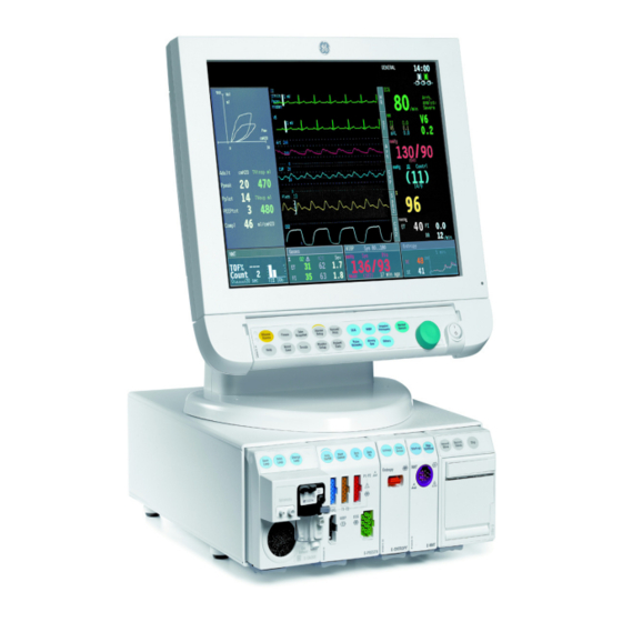
Datex-Ohmeda S/5 Anesthesia and Critical Care Monitors 3.3 Central Unit; S/5 8-Module Frame, F-CU8 Figure 7 Central Unit: S/5 8-Module Frame, F-CU8 The front of the Central Unit, F-CU8, houses plug-in parameter modules which interface the system with external devices. The back of the Central Unit houses the system circuit boards, together with expansion slots which accommodate PC boards which interface with external devices and the Datex-Ohmeda Network. -
Page 35: Inserting The Parameter Modules
System installation Confirm that the network symbol and ‘Connected to Network’ message are displayed on the upper part of the screen. 3.3.3 Inserting the parameter modules Ensure that the module is properly orientated (i.e. module release latch facing downward). Align the module insertion guide slot with the frame insertion guide. Push the module into the frame until it clicks. -
Page 36: E-Psm(P) Mounting Accessories
With Interface Module for PSM, E-INTPSM, the Frame Mount or the Pole Mount can be connected to the Datex-Ohmeda S/5 F-CU8 frame equipped with software license 04 or later. The E-PSM(P) module can be attached to the Frame Mount or Pole Mount and used like a Datex-Ohmeda S/5 modular module. - Page 37 System installation Frame mount for PSM - Instructions for connecting to the F-CU8 frame 1. The correct drilling locations are marked through the MARK marking holes on the enclosed plate. 2. Set front and bottom of the plate as shown in the picture. 3.
-
Page 38: Positioning Pc Boards
Datex-Ohmeda S/5 Anesthesia and Critical Care Monitors Pole mount for PSM – Instructions for connecting to frame 1. Attach the E-PSM(P) module to the Pole Mount. 2. Connect the cable of the Pole Mount for PSM to the F-CU8 with the E-INTPSM module (M1054424). -
Page 39: Replacing Pc Boards
System installation NOTE: Authorized personnel only may open the cover of 24Vdc input connector (use a flat screwdriver). 3.3.6 Replacing PC boards For service procedures refer to Part II. Make sure that the power of the monitor is turned off and unplug the power cord. Press and hold the service reset button on the rear panel for at least five seconds or until an audible tone is heard (see Figure... -
Page 40: Performing Factory Reset
Datex-Ohmeda S/5 Anesthesia and Critical Care Monitors 3.3.7 Performing Factory Reset NOTE: The factory reset is necessary after downloading of monitor software and after replacing the CPU board or SRAM/Timekeeper battery. NOTE: A factory reset will restore all customized defaults, including language selection, to factory defaults. -
Page 41: Mounting The Frame
System installation F-CU5(P) F-CPU signal cable N-AC F-CPU power cable F-CPU Power cord Figure 12 F-CU5 parts connected with cables Figure 13 Two F-CU5s connected to one F-CPU 3.4.1 Mounting the Frame The various mount options and connecting cables allow you to install the F-CU5(P) 5-Module Frame, F-CPU Central Processor Unit and N-AC Power Unit either in one package or separately. -
Page 42: Connecting To Mains
Datex-Ohmeda S/5 Anesthesia and Critical Care Monitors The different mounts to install the Central Unit F-CU5 Wall Mount Hanger for S/5 F-CU5 Power Adapter Mount for F-CU5 Power Unit N-AC Adapter Plate for S/5 F-CU5 Table Holder for S/5 F-CU5 Holder for S/5 Command Bar 3.4.2 Connecting to mains... -
Page 43: Inserting The Parameter Modules
System installation If necessary, change the monitor's network communication by selecting DRI Level and turning the ComWheel. NOTE: If the DRI level is changed, the monitor will restart automatically. Confirm that the network symbol and 'Connected to Network' message are displayed on the upper part of the screen. -
Page 44: Positioning Pc Boards
Datex-Ohmeda S/5 Anesthesia and Critical Care Monitors WARNING When detaching modules, be careful not to drop them. Always support with one hand while pulling out with the other. WARNING Do not use modules with identical measurements in the same monitor. If such modules have been inserted, remove the module that has been most recently connected. -
Page 45: Replacing Pc Boards
System installation 3.4.6 Replacing PC boards For service procedures refer to Part II. Make sure that the power is turned off the Monitor and unplug the power cord. Press and hold the service reset button on the rear panel of the F-CPU for at least five seconds or until an audible tone is heard (see Figure 15). -
Page 46: Displays
Datex-Ohmeda S/5 Anesthesia and Critical Care Monitors 3.5 Displays D-FPD15 19’’ medical grade display D-LCC12A Figure 16 Display options 3.5.1 Main displays The main display options are integrated with an S/5 Command Bar and a ComWheel: • 15” Flat Panel Display, D-FPD15 •... -
Page 47: 15" Flat Panel Display, D-Fpd15
System installation WARNING The displays must only be used together with the original type of power adapter. CAUTION The LCD displays are fragile. Ensure that the LCD displays are not placed near a heat source or exposed to mechanical shocks, pressure, moisture, or direct sunlight. -
Page 48: 12" Lcd Display, D-Lcc12A
Datex-Ohmeda S/5 Anesthesia and Critical Care Monitors Install/Service (password 16-4-34) – Installation - Display Setup NOTE: After changing the resolution, the monitor must be restarted before the new setting becomes effective. If the resolution setting is not correct after the monitor restart, check that... -
Page 49: 19" Medical Grade Display
System installation Mounting to Display arm Mount the LCD Display, D-LCC12A to a pedestal, wall or ceiling mount, or to a display arm with appropriate parts. Connect the video cable to the display and tighten the video cable finger screws carefully. CAUTION To prevent any liquid from entering the LCD display casing, do not tilt the LCD display more than 45 degrees backward or 20 degrees forward. -
Page 50: Display Controller Boards
Datex-Ohmeda S/5 Anesthesia and Critical Care Monitors Connect the AC adapter’s DC plug into the displays power input. Connect the provided power cord in to the inlet of the auxiliary AC adapter. Then, connect plug to the mains outlet. Connect the DVI cable to the connector X2 on the CPU board, B-CPU6. Tighten the finger screws. -
Page 51: Resolution Selection For Optional B-Dispx
System installation Resolution settings are made by dip switch S3 S3 S2 S3 switches sw1 sw2 Auto SVGA Figure 18 Resolution dip switch settings, B-DISPX 3.6.2 Resolution selection for optional B-DISPX The resolution selection dip switch positions are presented in Figure 18 Resolution dip switch settings, B-DISPX. -
Page 52: S/5 Airway Modules
Datex-Ohmeda S/5 Anesthesia and Critical Care Monitors 3.8 S/5 Airway Modules 3.8.1 S/5 Compact Airway Modules, E-xxxx This chapter provides information for installing Compact Airway Modules E-xxxxx. Figure 19 Compact Airway Module, E-XXXX Connection to Central Unit Ensure that the module is properly orientated (i.e. module release latch facing downward). -
Page 53: Figure 20 Scavenging Through Ventilator Reservoir
System installation Scavenging through the ventilator reservoir SAMPLE GAS OUT Figure 20 Scavenging through ventilator reservoir Connect an exhaust line to the sample gas outlet on the module’s front panel. Attach the other end of the line to the ventilator reservoir. Make sure that the reservoir tube diameter is at least 2 - 3 times larger than the exhaust line. -
Page 54: Record Keeping Keyboard For Anesthesia, K-Arkb
Datex-Ohmeda S/5 Anesthesia and Critical Care Monitors Connecting directly to the vacuum scavenging system Connect the exhaust line to the monitor’s sample gas outlet. Connect the exhaust line only to an open scavenging system where gas is removed at room pressure. Do not connect the monitor directly to a vacuum scavenging system. -
Page 55: Ark Barcode Reader, N-Scan (Optional)
System installation 3.10 ARK Barcode Reader, N-SCAN (optional) 3.10.1 Connection to Central Unit/LCD Display or D-LCC12A The ARK Barcode Reader, N-SCAN, can be connected to the Record Keeping Keyboard for Anesthesia, K-ARKB, and to the LCD Display or D-LCC12A using a Y-cable as illustrated in Figure 23 below. -
Page 56: S/5 Extension Frame, F-Ext4, With F-Cu8 Only
Datex-Ohmeda S/5 Anesthesia and Critical Care Monitors Figure 24 N-SCAN Barcode Reader connection directly to the keyboard Barcode Reader is configured compatible to your monitor and necessary information is delivered with the monitor. WARNING When using the ARK Barcode Reader, N-SCAN, do not stare into beam. -
Page 57: Mounting Of Extension Frame, F-Ext4
System installation 3.11.1 Mounting of Extension Frame, F-EXT4 When mounting the Extension Frame, F-EXT4, for instance to an IV pole, make sure that this does not affect the stability of the IV pole. 3.11.2 Connection to Central Unit Insert the Extension Module, E-EXT, into the Central Unit. Firmly press the module into position. Connect the Extension Module cable to the Extension Frame. - Page 58 Datex-Ohmeda S/5 Anesthesia and Critical Care Monitors Document no M1137263-04...
-
Page 59: Interfacing
Interfacing Interfacing External devices can be interfaced with the S/5 Anesthesia and Critical Care Monitors via the UPI4 and UPI4NET boards, B-UPI4 and B-UPI4NET, via the Interface Module, E-INT, and via the Device Interfacing Solution, N-DISxxx. A UPI4 and UPI4NET board can be used for interface with: •... -
Page 60: Connection To External Datex-Ohmeda Monitors
Datex-Ohmeda S/5 Anesthesia and Critical Care Monitors Table 4 Transference of parameters, Datex-Ohmeda monitors Device Waveforms Numerics Alarms (analog) Cardiocap E-INT -> CO Et&Fi Airway gases, None Respiration rate, , Pulse rate Capnomac E-INT -> CO , Pleth Et&Fi Airway gases,... -
Page 61: Connection To Critikon Dinamap 1846Sx, Abbott Oximetrix 3 And Baxter Explorer
Interfacing 4.1.2 Connection to Critikon Dinamap 1846SX, Abbott Oximetrix 3 and Baxter Explorer Use the INT-External Device Cable. Make sure that the power to both monitors is turned off. Connect the 9 pin D-connector to the Interface Module, E-INT. Tighten the finger screws. Connect the 25 pin D-connector to the connector on the external monitor. - Page 62 Datex-Ohmeda S/5 Anesthesia and Critical Care Monitors Document no M1137263-04...
-
Page 63: Interfacing External Bedside Devices Via Device Interfacing Solutions, N-Disxxx
Trademark of Dräger Medical AG & Co Trademark of Nellcor Puritan Bennet Inc Trademark of Maquet Critical Care AB part of the Getinge Group (previously trademark of Siemens) Trademark of GE Healthcare Finland Oy Replaced by N-DISVENT Device Monitors N-DISOXIM3... -
Page 64: Device Interfacing Solution Components
Datex-Ohmeda S/5 Anesthesia and Critical Care Monitors N-DISRGM RGM Monitor N-DISTONO Tonocap N-DISWHITE Capnomac, Capnomac II Multicap, Normocap, CD2-O2 Capnomac Ultima Normocap CD-200 Oscar Oxy, Cardiocap 1GS, Cardiocap 2GS Satlite, Satlite Trans, Satlite Plus Trademark of Hospira Inc. (previously trademark of Abbott Laboratories) -
Page 65: Mounting
Interfacing label specifying the external device LED indicators black bus cable from another interfacing module, if needed grey device specific cable to the communication port of the external device black bus cable to the monitor’s DIS connector (or to another interfacing module) Figure 26 Connection cables and LED indicators... -
Page 66: Selecting The External Device
Datex-Ohmeda S/5 Anesthesia and Critical Care Monitors Figure 27 An example of interfacing external devices with Device Interfacing Solution Datex-Ohmeda S/5 Anesthesia Monitor (with software L-ANE02(A) or later) Aestiva/5 anesthesia machine RGM monitor Interfacing module NOTE: You can connect up to ten (10) interfacing modules to one system simultaneously. -
Page 67: Functional Check
Interfacing 4.2.5 Functional check There are two ways to check the function of the Device Interfacing Solution: Monitor Setup Press the key. Select Interfacing and open the Status Page menu. The status page shows you the current communication status of the interfacing module (1 - 10). NOTE: The status message ‘Connected’... -
Page 68: Interfacing Datex-Ohmeda Anesthesia Delivery Unit
Datex-Ohmeda S/5 Anesthesia and Critical Care Monitors 4.3 Interfacing Datex-Ohmeda Anesthesia Delivery Unit It is possible to interface the Datex-Ohmeda Anesthesia Delivery Unit to the S/5 Anesthesia Monitor via the UPI Board, B-UPI4 or UPINET Board, B-UPI4NET. The data link is bi-directional. -
Page 69: Interfacing Dräger Cicero, Cato, Julian And Narkomed 2C (By Nad)
Interfacing Table 8 Events transferred from S/5 Anesthesia Delivery Unit to the S/5 Anesthesia Monitor Events transferred once a minute Ventilator settings Ventilation (mode) Tidal Volume Minute Volume Resp. Rate I:E Times: inp I:E Times: exp InspPause Ventilator measurements Ppeak Pplat Peep Pmin... -
Page 70: Interconnection
Datex-Ohmeda S/5 Anesthesia and Critical Care Monitors 4.4.1 Interconnection Use the INT-External Device Cable, except for Julian and Cicero EM, in which case use the INT-Julian/Cicero EM cable. Make sure that the power to both monitors is turned off. Connect the 9 pin D-connector to the Interface Module, E-INT. Tighten the finger screws. - Page 71 Interfacing Table 10 Parameters transferred from Dräger Cato, Julian and Narkomed 2C (NAD) monitor to the S/5Anesthesia Monitor or S/5Critical Care Monitor Selection Waveforms Numerics States Gases / SSS (kPa, mmHg, %) Fi & Et (kPa, %) None Fi & Et(%) O Fi &...
-
Page 72: Interfacing Printer
It is possible to interface a computer to the S/5 Anesthesia Monitor and to the Critical Care Monitor. Contact your authorized GE Healthcare distributor for further advice on computer interface. WARNING Always make sure that the combination complies with the international safety standard IEC 60601-1-1 for medical electrical systems and with the requirements of local authorities. -
Page 73: Output Signals
Interfacing 4.7 Output signals 4.7.1 UPI4NET Board output signals Analog/ digital output signals on the connectors X7 can be used for interfacing with other devices. The pin assignments are illustrated in tables/pictures below. Table 11 Coding element connector, X4 9 pin female D-connector Signal IDCS1 (chip select) IDCL (clock) -
Page 74: Analog Outputs
Datex-Ohmeda S/5 Anesthesia and Critical Care Monitors If the output signals are used simultaneously with the coding element, the B-UPINET Y-cable, order number 889308, is recommended. 4.7.3 Analog outputs Direct ECG B-UPI4NET -02 (X7 pin 8) Delay (max.): <15 ms Gain ECG (out)/ECG (in): 1 V/mV ±20%... -
Page 75: Functional Check
Monitor and S/5 Critical Care Monitor. The functional check is mandatory after monitor installation. These instructions include a “Functional check form, Datex-Ohmeda S/5 AM, CCM” which may be used when performing the procedures. The symbol in the instructions indicates that the check form contains space to record the results of the particular procedure. - Page 76 Datex-Ohmeda S/5 Anesthesia and Critical Care Monitors For product(s) Tool Order No. Multi-Link ECG accessories, IEC E-PSM(P)/ E-PRESTN Multi-link 3-leadwire set 412682-003 Multi-link 5-leadwire set 412681-003 Multi-link 5-leadwire set, C2-C6 416467-004 E-PRESTN w/ (E12) Multi-link 12-lead ECG trunk 416035-002 cable...
-
Page 77: Hemodynamic Patient Simulators
Functional check see section “Adjustments and calibrations” in Compact Airway modules slot in E-Modules Technical Reference Manual. For details on recommended accessories see “Supplies and Accessories” catalog. 5.1.1 Hemodynamic patient simulators The following tables present the patient simulators’ compatibility with each hemodynamic module, and the accessories needed: Table 14 Patient simulators’... -
Page 78: Functional Inspection
Datex-Ohmeda S/5 Anesthesia and Critical Care Monitors − F-CU8: the equipotential tap and all the screws are tightened properly. − sampling line is connected to the Airway Module, if installed. Check that modules go in smoothly and lock up properly in all module slots. -
Page 79: Display(S)
Functional check Airway Gas -Spirometry Setup -Scaling -Indep. -Paw Scale –20 -Flow Scale –15 Ventil. -Spirometry Setup -Scaling -Indep. -Paw Scale –20 -Flow Scale –15 Others -Resp Setup -Size -1.0 - Resp Rate Source – AUTO - Measurement – ON - Detection Limit –... -
Page 80: 5-Module Central Unit, F-Cu5/ 8-Module Central Unit, F-Cu8
Datex-Ohmeda S/5 Anesthesia and Critical Care Monitors 5.3.4 5-Module Central Unit, F-CU5/ 8-Module Central Unit, F-CU8 Check that all the fans in the N-AC, F-CPU and F-CU5(P) are / the frame fan in F-CU8 is running. Check that the clock on the screen shows correct time. Readjust the time and date, if necessary. -
Page 81: Single Width Airway Module, E-Minic
Functional check 5.3.7 Single width Airway Module, E-miniC Wait until the message ‘Calibrating gas sensor’ disappears from the screen. Block the tip of the sampling line with your finger and check that the message ‘Sample line blocked’ appears on the monitor screen within 30 seconds. Detach the Mini D-fend and check that the message ‘Check D-fend’... -
Page 82: Pressure/Pressure Temp Modules, E-P, E-Pt
Datex-Ohmeda S/5 Anesthesia and Critical Care Monitors Perform a NIBP measurement and check that the module gives a reasonable measured result. 5.3.9 Pressure/Pressure Temp Modules, E-P, E-PT Invasive blood pressure measurement Zero P3 Check the function of the front panel key. -
Page 83: Masimo Compatible Saturation Module, E-Masimo
Functional check 5.3.12 Masimo Compatible Saturation module, E-MASIMO Connect a Masimo SpO2 finger probe to the module. Check that the message ‘Check probe’ is displayed on the screen within 30 seconds. Attach the SpO2 probe on your finger. Check that a reading of 95-100 and a proper SpO2 waveform appear. -
Page 84: Recorder Module
Datex-Ohmeda S/5 Anesthesia and Critical Care Monitors 5.3.17 Recorder module Record Wave Press the module key and check that the module starts recording the Stop selected waveforms. Press the module key to stop recording. Check that the quality of the recordings is acceptable. -
Page 85: General
Functional check 5.3.22 General • Switch the monitor to standby • Perform final cleaning • Fill in all necessary documents Document no. M1137263-04... - Page 86 Datex-Ohmeda S/5 Anesthesia and Critical Care Monitors Document no M1137263-04...
-
Page 87: General Troubleshooting
General troubleshooting General troubleshooting Monitor not functioning On/Stby sw itch "ON"? Display connected and Connect and check pow ered? Keyboard connected? The problem w as caused by Monitor starts loosen unit(s) functioning? Mains Disconnect and reconnect the pow er cord connected? Possible intrconnecting pow er cord. -
Page 88: Software Troubleshooting
Datex-Ohmeda S/5 Anesthesia and Critical Care Monitors 6.1 Software troubleshooting For information on software troubleshooting, see “Software Download Tool - User Instructions.” Document no M1137263-04... -
Page 89: Appendix A: Functional Check Form, Datex-Ohmeda S/5 Am, Ccm
Appendix Functional check form, Datex-Ohmeda S/5 AM, CCM APPENDIX A: Functional check form, Datex-Ohmeda S/5 AM, CCM Customer Service Service engineer Date Measuring equipment / test gases used: Equipment / tool / gas: Manufacturer: Model/Type/Part Serial Number / Calibration Number:... - Page 90 Datex-Ohmeda S/5 Anesthesia and Critical Care Monitors Functional Inspection N.A. Fail 5.3.4. 5-Module Central Unit, F-CU5/ 8-Module Central Unit, F-CU8 5.3.5. Extension Frame, F-EXT4 Notes 5.3.6. Compact Airway Module, E-CXXXXX . Compact Airway Modules with the Patient Spirometry option . For all Compact Airway Modules 5.3.7.
- Page 91 Appendix Functional check form, Datex-Ohmeda S/5 AM, CCM Functional Inspection N.A. Fail 5.3.11. Cardiac Output Modules, E-COP, E-COPSv . Invasive blood pressure measurement . Cardiac Output measurement Notes 5.3.12. Masimo Compatible Saturation module, E-MASIMO 5.3.13. Nellcor Compatible Saturation module, E-NSATX 5.3.14.
- Page 92 Datex-Ohmeda S/5 Anesthesia and Critical Care Monitors Functional Inspection N.A. Fail 5.3.22. General • Perform final cleaning • Fill in all necessary documents Notes Signature A4(4) Document no M1137263-04...
- Page 93 Appendix ElectroMagnetic Compatibility APPENDIX B: ElectroMagnetic Compatibility Table 1 Guidance and manufacturer’s declaration – electromagnetic emissions Guidance and manufacturer’s declaration – electromagnetic emissions The S/5™ AM or CCM is intended for use in the electromagnetic environment specified below. The customer or the user of the S/5™ AM or CCM should assure that it is used in such an environment. Emissions test Compliance Electromagnetic environment - guidance...
- Page 94 Datex-Ohmeda S/5 Anesthesia and Critical Care Monitors Table 2 Guidance and manufacturer’s declaration – electromagnetic immunity Guidance and manufacturer’s declaration – electromagnetic immunity The S/5™ AM or CCM is intended for use in the electromagnetic environment specified below. The customer or the user of the S/5™...
-
Page 95: Appendix B: Electromagnetic Compatibility
Appendix ElectroMagnetic Compatibility Table 3 Guidance and manufacturer’s declaration – electromagnetic immunity Guidance and manufacturer’s declaration – electromagnetic immunity The S/5™ AM or CCM is intended for use in the electromagnetic environment specified below. The customer or the user of the S/5™ AM or CCM should assure that it is used in such an environment. Immunity test IEC 60601 test level Compliance... - Page 96 Datex-Ohmeda S/5 Anesthesia and Critical Care Monitors NOTE 1 At 80 MHz and 800 MHz, the higher frequency range applies. NOTE 2 These guidelines may not apply in all situations. Electromagnetic propagation is affected by absorption and reflection from structures, objects and people.
- Page 97 Appendix ElectroMagnetic Compatibility Table 4 Recommended separation distances between portable and mobile RF communications equipment and the S/5™ AM or CCM Recommended separation distances between portable and mobile RF communications equipment and the S/5™ AM or CCM The S/5™ AM or CCM is intended for use in an electromagnetic environment in which radiated RF disturbances are controlled.
- Page 98 Datex-Ohmeda S/5 Anesthesia and Critical Care Monitors For your notes: B6(6) Document no M1137263-04...
- Page 99 CAUTION: U.S. Federal law restricts this device to sale by or on the order of a licensed medical practitioner. Outside the USA, check local laws for any restriction that may apply. All specifications subject to change without notice. Document number M1125633-06 June 18, 2009 GE Healthcare Finland Oy Datex-Ohmeda Inc. Helsinki, Finland P.O. Box 7550 P.O. Box 900...
- Page 101 Table of contents Table of contents Planned maintenance instructions Introduction ................1 Recommended tools .
- Page 102 Datex-Ohmeda S/5 Anesthesia and Critical Care Monitors Document no M1125633-06...
-
Page 103: Planned Maintenance Instructions
Planned maintenance instructions Planned maintenance instructions 1.1 Introduction These instructions include procedures for planned maintenance (PM) for the Datex-Ohmeda S/5 Anesthesia Monitor and S/5 Critical Care Monitor. The Planned maintenance should be performed once a year. These instructions include “Planned maintenance check form, S/5 Anesthesia and S/5 Critical Care Monitor”... -
Page 104: Recommended Tools
Datex-Ohmeda S/5 Anesthesia and Critical Care Monitors 1.2 Recommended tools NOTE: Use only properly maintained, calibrated and traceable measurement equipment for the specified calibrations and adjustments to ensure accuracy. For product(s) Tool Order No. All Airway modules Flowmeter Compact Airway Module, E-CAiO(VX) -
Page 105: Hemodynamic Patient Simulators
Planned maintenance instructions For product(s) Tool Order No. E-COP, E-COPSv C.O. Catheter cable 16590 E-COPSv simulator 890121 EEG Module, E-EEG Earphones EEG simulator 90502 BIS Module, E-BIS BIS simulator or 900509 BIS Sensor simulator 900508 E-ENTROPY Simulator for E-ENTROPY N-ES Entropy sensor cable 8002964 E-NMT... -
Page 106: Recommended Parts
Datex-Ohmeda S/5 Anesthesia and Critical Care Monitors Table 2 Adapter cables for hemodynamic patient simulators Patient simulator Hemodynamic patient simulator Dual temperature adapter cable 402015-004 Hemodynamic patient simulator Dual Inv.BP adapter cable 2005772-001 Medsim Temperature adapter cable M1010832 Medsim Inv.BP adapter cable M1010858 Lionheart &... -
Page 107: Planned Maintenance Parts
Planned maintenance instructions 1.4 Planned maintenance parts 1.4.1 PM parts for Compact Airway Modules, E-CXX with CO2 absorber - Anesthesia and Critical Care Part Order No. Special tube 300 mm (Nafion) 733382-HEL Special tube 130 mm (Nafion) M1080137 Ref. gas sticker 893110-HEL Ref. - Page 108 Datex-Ohmeda S/5 Anesthesia and Critical Care Monitors Document no M1125633-06...
-
Page 109: Planned Maintenance Check List
Planned maintenance check list Planned maintenance check list 2.1 Visual inspection/preparation 2.1.1 General WARNING Wear a static control wrist strap when handling PC boards. Electrostatic discharge may damage components on the board. Make sure that the monitor is switched to standby. Disconnect the mains power cord. -
Page 110: Single-Width Airway Module, E-Minic
Datex-Ohmeda S/5 Anesthesia and Critical Care Monitors NOTE: Make sure that the tubes are not in contact with the sampling pump or the O sensor, or its springs. NOTE: Check that tubes are not contaminated. Any contamination inside the tubing can increase a risk of faulty operation in valves or sensors. -
Page 111: Modules With Nibp Measurement
Planned maintenance check list NOTE: Avoid contact with the rubber paper roller. Be careful to limit the application of alcohol to the thermal printhead and the window. − Reinstall the paper roll. 2.1.6 Modules with NIBP measurement Check the NIBP filter. Replace the filter, if necessary. Plug the module back into the frame. - Page 112 Datex-Ohmeda S/5 Anesthesia and Critical Care Monitors Record/Print - Record Waveforms - Waveform 1 - ECG1 - Waveform 2 - P1 - Waveform 3 - P2 Invasive Pressures - P1 ‘ART’ Setup - Label - ART - P2 ‘CVP’ Setup - Label - CVP...
-
Page 113: Display
Planned maintenance check list 2.2.2 Display Check that the picture on the screen is adjusted correctly. Readjust the picture with the adjustment knobs or with the display menu keys, if necessary. 2.2.3 Keyboard(s) Tests with the Command Bar: − Help Press the key. -
Page 114: Extension Frame, F-Ext4
Datex-Ohmeda S/5 Anesthesia and Critical Care Monitors 2.2.5 Extension Frame, F-EXT4 If the F-EXT4 contains a fan, check that the fan is running. Check that the modules in the F-EXT4 are recognized, i.e. the required parameter information is shown on the monitor screen. -
Page 115: Single-Width Airway Module, E-Minic
Planned maintenance check list Patient Spirometry Compact Airway Modules with the option 11. Enter the Spirometry service menu. Connect a clean spirometry tube and D-lite to the module. Perform the spirometry leak test. 12. Connect the sampling line. Breathe through the wider side of the D-lite. Check that the flow waveform moves downwards when you breathe in, and upwards when you breathe out. -
Page 116: Multiparameter Hemodynamic Modules
Datex-Ohmeda S/5 Anesthesia and Critical Care Monitors NOTE: Noisy sampling pump might indicate possible problems with motor bearing. Replace the noisy sampling pump by new one if needed. 2.2.8 Multiparameter Hemodynamic Modules ECG and RESP measurements Enter the ESTP: ECG service menu. - Page 117 Planned maintenance check list Temperature measurement Enter the ESTP: STP service menu. Check that the Time-outs, Bad checksums and Bad c-s by mod values are not increasing faster than by 5 per second. Check that the STP board memories have passed the internal memory test, i.e.
-
Page 118: Eeg Module, E-Eeg And Eeg Headbox, N-Eeg
Datex-Ohmeda S/5 Anesthesia and Critical Care Monitors E-PSM(P), E-PRESTN: 21. Attach a NIBP cuff hose without cuff identification and check that the module identifies the hose: − The message ‘Select inflation limits’ appears in the NIBP digit field. − When you try to start the measurement, the monitor automatically opens the selections NIBP Setup - Inflation Limits. - Page 119 Planned maintenance check list Sensor Check Check the membrane keys of the module. Stay in the module view and press each key for at least one second and check that the key being pressed is identified, i.e. the corresponding 'PUSHED' text appears in the service menu. Check that ‘Messages from BE’...
- Page 120 Datex-Ohmeda S/5 Anesthesia and Critical Care Monitors 2.2.12 Pressure/Pressure Temp Modules, E-P, E-PT Enter the P/PT module service menu: Check that the Time-outs, Bad checksums and Bad c-s by mod values are not increasing faster than by 5 per second. Check that the PT board memories have passed the internal memory test, i.e.
-
Page 121: 15Neuromuscular Module, E-Nmt
Planned maintenance check list Invasive blood pressure measurement Zero P4 Check the function of the front panel membrane key. Check the InvBP channel with a patient simulator. Zero the InvBP channel. Then check that the values and waveforms correspond to the simulator settings. - Page 122 Datex-Ohmeda S/5 Anesthesia and Critical Care Monitors Check that the message ‘Cable off’ is shown in the digit field and that ‘Cable’ on the service menu states OFF. Plug the NMT Sensor Cable with the NMT ElectroSensor into the front panel connector NMT.
-
Page 123: 19Recorder Module, E-Rec
Planned maintenance check list Attach the SpO probe on your finger. Check that a reading of 95-100 and a proper SpO waveform appear. 2.2.18 Memory Module, E-MEM Check that the module is recognized properly, i.e. Present and Active state YES. Check that the memories and the PCMCIA controller have passed the tests. - Page 124 Datex-Ohmeda S/5 Anesthesia and Critical Care Monitors 2.2.21 Interface Module, E-INT Enter the Interface service menu: Check that the Time-outs, Bad checksums and Bad c-s by mod values are not increasing faster than by 5 per second. Check that the memories have passed the internal memory test, i.e.
- Page 125 Planned maintenance check list Final cleaning Switch the monitor to standby and perform final cleaning. Fill in all necessary documents. Document no. M1125633-06...
- Page 126 Datex-Ohmeda S/5 Anesthesia and Critical Care Monitors Document no M1125633-06...
- Page 127 Appendix Planned maintenance check form, S/5 Anesthesia and S/5 Critical Care Monitor APPENDIX A: Planned maintenance check form, S/5 Anesthesia and S/5 Critical Care Monitor Customer Service Service engineer Date Measuring equipment / test gases used: Equipment / tool / gas: Manufacturer: Model/Type/Part Serial Number /...
- Page 128 Datex-Ohmeda S/5 Anesthesia and Critical Care Monitors Functional Inspection N.A. Fail 2.2.1. General 2.2.2. Display 2.2.3. Keyboard(s) 2.2.4. 5-Module Frame, F-CU5(P) / 8-Module Frame, F-CU8 2.2.5. Extension Frame, F-EXT4 Notes 2.2.6. Compact Airway Module, E-CXXXXX . Anesthesia Agent . Patient Spirometry .
- Page 129 Appendix Planned maintenance check form, S/5 Anesthesia and S/5 Critical Care Monitor Functional Inspection N.A. Fail 2.2.9. EEG Module, E-EEG and EEG Headbox, N-EEG 2.2.10. BIS Module, E-BIS 2.2.11. Entropy Module, E-ENTROPY Notes 2.2.12. Pressure/Pressure Temp Modules, E-P, E-PT . Invasive blood pressure measurement .
- Page 130 Datex-Ohmeda S/5 Anesthesia and Critical Care Monitors Functional Inspection N.A. Fail 2.2.21. Interface Module, E-INT 2.2.22. Device Interfacing Solution, N-DISxxx Notes 2.2.23. General 1. Storing trend data 2. Service reset 3. Watchdog for Display Controller on B-CPU6 Board 4. Service Log reset 5.
- Page 131 CAUTION: U.S. Federal law restricts this device to sale by or on the order of a licensed medical practitioner. Outside the USA, check local laws for any restriction that may apply. All specifications subject to change without notice. Document number M1137266-02 June 18, 2009 GE Healthcare Finland Oy Datex-Ohmeda Inc. Helsinki, Finland P.O. Box 7550 P.O. Box 900...
- Page 133 Table of contents Table of contents Table of contents List of tables Introduction Frame Display Controller ..............4 Memory .
- Page 134 Datex-Ohmeda S/5 Anesthesia and Critical Care Monitors 4.7.4 NIBP Pulse Valve ............. . 35 4.7.5...
- Page 135 List of tables List of tables Table 1 Ethernet service data .............................. 7 Table 2 Module general status ............................44 Table 3 Module hardware status............................. 45 Table 4 Module keyboard status............................45 Table 5 Module general error status..........................45 Table 6 Module pneumatics error status........................
- Page 136 Datex-Ohmeda S/5 Anesthesia and Critical Care Monitors Document no M1137266-02...
-
Page 137: Introduction
Service Menu Introduction The monitor has a Service Menu, which is a useful tool to examine monitor functions and to troubleshoot in case a fault occurs. Service Menu structure Service Menu Disp Controller Memory Network Network Config Frame Ethernet MemCards Power Supply Battery CPU Board... - Page 138 Datex-Ohmeda S/5 Anesthesia and Critical Care Monitors Service Menu NOTE: The Service Menu pictures and parameter values are for reference only. Details on the menu page can vary depending on the software version and the module type in use. To enter the service menu: Monitor Setup 1.
-
Page 139: Frame
Service Menu Frame The frame menu includes service menus common for the frame. Document no. M1137266-02... -
Page 140: Display Controller
Datex-Ohmeda S/5 Anesthesia and Critical Care Monitors 1.1 Display Controller Controller 1 details of the 1 display controller. Controller 2 details of the 2 display controller. Controller 3 details of the 3 display controller. Previous Menu a selection to return to the previous menu. -
Page 141: Memory
Connections: Names of the subnet id:s connected. The field represents the subnet status menus, i.e. shows the connected subnets. The first three connections are reserved permanently for Datex-Ohmeda Central, and the fourth is reserved for another subnet, e.g. Datex-Ohmeda S/5 Arrhythmia Workstation. Document no. M1137266-02... -
Page 142: Network Config
Datex-Ohmeda S/5 Anesthesia and Critical Care Monitors Subnet Status The Subnet status view gives more accurate information of the different subnet id:s connected. All four Subnet status menus have a similar structure. The number of different packets transmitted and received by the monitor are shown in the columns below Tx and Rx. -
Page 143: Ethernet
Service Menu 1.3.3 Ethernet The Ethernet Status view shows the general status of the ethernet network communication. Driver: Ethernet chip name (82559ER) Cable: Indicates if the ethernet cable is connected. EthernetAddr: Monitor’s ethernet address. Speed: Indicates the current ethernet communication speed. The service data related to the ethernet status view is described in the following table. -
Page 144: Memcards
Datex-Ohmeda S/5 Anesthesia and Critical Care Monitors 1.4 MemCards 1.4.1 Status Module Present indicates whether the memory module is firmly attached to the monitor. Possible values are YES and NO. Module Active indicates whether the module services are available. Possible values are YES and ROM indicates the status of the ROM memory of the module. -
Page 145: Communication
Service Menu 1.4.2 Communication Interface status indicates the status of the data link between the monitor and memory module. If the memory module is properly attached, the status should always be on ACTIVE. If the status blinks between ACTIVE and CLOSED, a communications error has occurred: remove the module briefly, and insert it back to the monitor frame to check if the error disappears. -
Page 146: Power Supply
Datex-Ohmeda S/5 Anesthesia and Critical Care Monitors 1.5 Power Supply The menu shows the voltages and temperature measured by the UPI4(NET) board. The measurement starts about 100 ms after a start-up. The values in the column under Mean are the mean values of the... -
Page 147: Cpu Board
Service Menu 1.6 CPU board The menu shows the temperature measured by the Central prosessing board. Temp (°C) value corresponds with the Central Unit internal temperature measured at the location of the CPU6 board. A/D values shows the A/D value of temperature measurement. -
Page 148: Display
Datex-Ohmeda S/5 Anesthesia and Critical Care Monitors Display Geometry views the geometry of the display. Colors views the color of the screen. Readability views the readability of the screen. Document no M1137266-02... -
Page 149: Keyboard
Service Menu Keyboard Keyboard The service menu for testing the command board functions. Upper Led is for testing the upper alarm LED (red) on the command board. When the text is highlighted, the upper alarm LED can be turned on and off by pressing the ComWheel. -
Page 150: Keyboard Log
Datex-Ohmeda S/5 Anesthesia and Critical Care Monitors 3.1 Keyboard Log Keyboard Scroll Log All the keyboard presses and the commands given by the ComWheel are recorded in the Keyboard Log. The keyboard log is saved in the permanent memory of the monitor. The length of the log is 1150 events. -
Page 151: Parameters
Service Menu Parameters NOTE: Parameter values in Service Data fields are only for reference in this section. 4.1 Gas Unit Service menu for airway gas modules’ communication and airway gas and spirometry measurements. Document no. M1137266-02... -
Page 152: General
Datex-Ohmeda S/5 Anesthesia and Critical Care Monitors 4.1.1 General Service Data Module configuration shows which measurement options are available, i.e. are detected by the module. Timeouts is a cumulative number that indicates how many times the module has not responded to the monitor's inquiry. -
Page 153: Gases
Service Menu 4.1.2 Gases Noise Meas activates the noise measurement. Sample gain adj adjusts the sampling pump gain, i.e. for adjusting the sample flow measurement. Fall time Meas * activates the fall time measurement. Pump ctrl A manual control for the sampling pump. -
Page 154: Spirometry
Datex-Ohmeda S/5 Anesthesia and Critical Care Monitors 4.1.3 Spirometry Insp and exp flow gains can be adjusted, if calibration is needed. A calibration pump or spirometry tester is used and readings are observed from the display. If a deviation exists, gains are adjusted accordingly. Gain scaling is 1.000, when the factory settings are in effect... - Page 155 Service Menu Service Data Sensor ADULT/PEDIATRIC according to the selected measurement mode (sensor). Insp/Exp Flow Gains shown apply to the selected sensor. Aw Press Zero and Flow Zero are the result of zeroing in the user service menu. They can be adjusted in the factory calibration menu, but not permanently stored.
-
Page 156: Ecg Module
Datex-Ohmeda S/5 Anesthesia and Critical Care Monitors 4.2 ECG Module Power freq: Set power frequency; 50 Hz/60 Hz. Filter low Set filter low frequency; 0.05 Hz/0.5 Hz. Filter high: Set filter high frequency; 30 Hz (40 Hz if power freq is 60 Hz) /100 Hz or 150 Hz @ NE12STPR. -
Page 157: Ecg Setup
Service Menu 4.2.1 ECG Setup Filter filters the ECG signal high frequency noise and slow respiratory artefacts. Monit (monitor) filter is used in routine monitoring. It effectively filters the artefacts caused by the electrosurgery unit and respiration. Diagn (diagnostic) filter is used if more accurate information of the waveform is needed (e.g. -
Page 158: Estp Module
Datex-Ohmeda S/5 Anesthesia and Critical Care Monitors 4.3 ESTP Module Service menu for the multiparameter hemodynamic module’s oxygen saturation, temperature and invasive pressure measurements. NOTE: Pressure Module, E-P and Pressure Temperature Module, E-PT have their own service menu; ”4.4 P/PT.”... - Page 159 Service Menu Balance between leds is adjusted by changing the intensity of red/infrared. Intensity of infrared (Ired int.) is in the range of 40 to 255 and red intensity (red int.) is in the range of 40 to 255. DC gain shows the gain of DC signal adjusted by the module. IDC is the value of infrared signal.
-
Page 160: Calibrations
Datex-Ohmeda S/5 Anesthesia and Critical Care Monitors 4.3.1 Calibrations Protection: Protection for the configuration and temperature calibrations can be set ON and OFF. Set Config: The module configuration should be set according to the module type. The setting is possible only when the protection is set OFF. The available selections are TP, ST or STP. -
Page 161: P/Pt
Service Menu 4.4 P/PT Service menu for Pressure Module, E-P, and Pressure Temperature Module, E-PT. Calibrations: see section “P/PT Calibrations”. Temp Test activates the automatic temperature test for the temperature channels T3 and T4. The result from the test is shown in the service data field. NOTE: The Temp Test needs to be selected twice before the test starts. -
Page 162: P/Pt Calibrations
Datex-Ohmeda S/5 Anesthesia and Critical Care Monitors RAM indicates the state of the RAM memory. ROM indicates whether the checksum at the EPROM is in accordance with the one the software has calculated. EEPROM indicates if the values stored in the permanent memory are valid. - Page 163 Service Menu Service menu for Dual Invasive Pressure Module, E-PP. Calibrations: see section ”PP Calibrations.” Record Data prints out the service data and circuit board information (id., serial number, and software id.) on the recorder. Service Data Gain is a coefficient to compensate for gain error. Usually the values for P5 and P6 are between 17000 and 25000.
-
Page 164: Pp Calibrations
Datex-Ohmeda S/5 Anesthesia and Critical Care Monitors 4.5.1 PP Calibrations Calibrate P5 and Calibrate P6 These functions are for calibrating the invasive blood pressure channels P5 and P6. How to calibrate The calibrations require a pressure transducer (with an appropriate cable) and a pressure manometer. -
Page 165: Cop
Service Menu 4.6 COP Service menu for Cardiac Output Module, E-COP, and Cardiac Output and Mixed Venous Oxygen saturation (SvO2) Module, E-COPSv. Record Data prints out the service data and module information (id. serial number and software id.) on the recorder. Service Data Gain is a coefficient to compensate for gain error. -
Page 166: Cop Calibrations
Datex-Ohmeda S/5 Anesthesia and Critical Care Monitors Timeouts is a cumulative number that indicates how many times the module has not responded to the monitor's inquiry. Bad checksums is a cumulative number that indicates how many times communication from the module to the monitor has failed. -
Page 167: Nibp Module
Service Menu 4.7 NIBP Module Service menu for non-invasive blood pressure measurement. Service Data Pressure shows the measured pressure multiplied by 10. This value is automatically zero-drift compensated. Zero shows the difference between the zeroing value in the permanent memory (stored when the module is calibrated) and the current automatic zero-drift compensation multiplied by 10. -
Page 168: Nibp Demo
Datex-Ohmeda S/5 Anesthesia and Critical Care Monitors 4.7.1 NIBP Demo A service menu for demonstrating the oscillometric method of NIBP measurement. The menu shows the real-time pressure signals that are measured from the NIBP cuff. The measurement result is shown in the adjoining digit field. -
Page 169: Nibp Calibration
Service Menu 4.7.2 NIBP Calibration Active Leak Test: Wrap an adult cuff around a rigid cylinder or pipe and connect the cuff to the module. Select the active leak test (ON). The module automatically pumps a pressure of 260 mmHg into the cuff. -
Page 170: Nibp Safety Valve
Datex-Ohmeda S/5 Anesthesia and Critical Care Monitors When the values are equal, push the ComWheel to confirm the calibration. After a few seconds the ‘Calibrated’ message will appear in the NIBP digit field, which means that the calibration data has now been saved. -
Page 171: Nibp Pulse Valve
Service Menu 4.7.4 NIBP Pulse Valve Start test is for starting and Stop test is for stopping the test. Set Valve lets you adjust the opening of the pulse valve. Pulse Valve Data For information on general items Pressure, Zero, Protect handle, Calibr. -
Page 172: Nibp Buttons/Leds
Datex-Ohmeda S/5 Anesthesia and Critical Care Monitors 4.7.5 NIBP Buttons/Leds The selections Auto ON/OFF, Manual ON/OFF, STAT ON/OFF, and Measur. ON/OFF have effect only on the NIBP module, M-NIBP. Buttons/Leds Data For information on general items Pressure, Zero, Protect handle, Calibr. prot., +15 V power, AD0 to AD7 as well as Timeouts etc., see section... -
Page 173: Nibp Pneumatics
Service Menu 4.7.6 NIBP Pneumatics Start Pump/Stop Pump: A manual control for the pump. The selection changes to Stop Pump when the pump turns on. Open Exh1/Close Exh1: A manual control for the exhaust valve 1. The selection changes to Close Exh1 when the valve is opened. -
Page 174: Nibp Watchdog
Datex-Ohmeda S/5 Anesthesia and Critical Care Monitors 4.7.7 NIBP Watchdog These menu items have only effect on the M-NIBP modules. They do not effect other NIBP modules. Test ADULT: is to test watchdog timer in adult mode (120 to 140 seconds). -
Page 175: Nmt
Service Menu 4.8 NMT Service menu for Neuromuscular Transmission Module, E-NMT. Start Curr. test is a test where the module itself checks the difference between a given current and the measured current. A 3 kΩ resistance should be connected between the stimulus electrodes before starting the test. -
Page 176: Nmt Setup
Datex-Ohmeda S/5 Anesthesia and Critical Care Monitors Timeouts is a cumulative number that indicates how many times the module has not responded to the monitor's inquiry. Bad checksums is a cumulative number that indicates how many times communication from the module to the monitor has failed. -
Page 177: Oxygen Saturation Module, E-Nsatx, E-Masimo
Service Menu 4.9 Oxygen Saturation Module, E-NSATX, E-MASIMO NOTE: Preamp Error is indicated on the service menu, even though module contains MP-204 board. SAT Data PR shows the pulse rate value [bpm] calculated from the pleth. % shows the oxygen saturation value multiplied by 100. -
Page 178: More
Datex-Ohmeda S/5 Anesthesia and Critical Care Monitors 4.10 More More... indicates that there are more parameter menus to be viewed. Document no M1137266-02... -
Page 179: Interface Module, E-Int
Service Menu 4.11 Interface module, E-INT Gases, SpO , NIBP, Spirometry, SvO /C.O. indicate the parameters for which service data is available. The data which can be seen on those pages is raw data from the interfaced monitors, which will be processed for the normal screen. -
Page 180: Tonometry
Datex-Ohmeda S/5 Anesthesia and Critical Care Monitors 4.12 Tonometry Service menu for Gastric Tonometry Module. Service Data Tonometry: A selection to enter the Tonometry setup menu. PressSensCal: A selection to enter the module pressure sensor calibration menu. System Test: A selection to enter the module system test. - Page 181 Service Menu Module hardware status. See Table 3 Module hardware status for a detailed description of the message. Table 3 Module hardware status bit 0 Lamp ON bit 1 Stepper motor ON bit 2 Zeroing valve ON bit 3 Pump valve ON bit 4-15 Not used Module key...
- Page 182 Datex-Ohmeda S/5 Anesthesia and Critical Care Monitors Pneuma error Module pneumatics error status. See Table 6 Module pneumatics error status for a detailed description of the message. Table 6 Module pneumatics error status Error label Description What to do pumping error...
- Page 183 Service Menu HW error Module hardware error status. See Table 7 Module hardware error status for a detailed description of the message. Table 7 Module hardware error status bit 0 Lamp error bit 1, 2, 3 not used bit 4 CPU EEPROM error bit 5 Sensor EEPROM error...
-
Page 184: Tonometry
Datex-Ohmeda S/5 Anesthesia and Critical Care Monitors 4.12.1 Tonometry Others This is another route to reach Tonometry setup menu, - Tonometry. For a detailed description on how to use this menu see “User’s Reference Manual”. Start / Stop Cycling is for starting or stopping the measurement. -
Page 185: Press Sensor
Service Menu 4.12.2 Press Sensor Start Calib.: A selection to start a module pressure sensor calibration sequence. The procedure is guided online. Record Data: A selection to print out the shown service data to the device defined in the ...Service - Record Data menu. -
Page 186: System Test
Datex-Ohmeda S/5 Anesthesia and Critical Care Monitors 4.12.3 System Test Start Test: A selection to start the automatic system test sequence. The procedure is guided online. Stop Test: A selection to stop the automatic system test sequence. Record Data: A selection to print out the shown service data to the device defined in the ...Service -... - Page 187 Service Menu Table 8 Description of system test Test label Description If test fails Pump unit function Stepper motor aspirates/pushes room air Check the function of stepper through the zeroing valve. If the stepper is motor. working properly, it is able to generate small negative/positive pressure at the pump unit pressure sensor.
- Page 188 Datex-Ohmeda S/5 Anesthesia and Critical Care Monitors 4.12.4 CO Sensor Lamp ON/OFF: A selection to toggle the sensor lamp on and off. Meas Signal: A selection to start an automatic signal measurement sequence. This sequence measures sensor lamp signal levels.
-
Page 189: Pneumatics
Service Menu 4.12.5 Pneumatics Zero valve: A selection to toggle the zero valve on/off. Press valve: A selection to toggle the pump valve on/ off. Record Data: A selection to print out the shown service data to the device defined in the ...Service - Record Data menu. - Page 190 Datex-Ohmeda S/5 Anesthesia and Critical Care Monitors 4.12.6 AD Record Data: A selection to print out the shown service data to the device defined in the ...Service - Record Data menu. TONO All the numbers in this section are AD counts, i.e.
-
Page 191: Eeg & Ep
Service Menu 4.13 EEG & EP Service menu for EEG Module for electroencephalography and evoked potentials (EP) measurements. Check Electr.: Headbox measures impedance of electrodes. Works the same way as from EEG menu or the headbox/module button. Start AEP: AEP measurement is started with current AEP settings. - Page 192 Datex-Ohmeda S/5 Anesthesia and Critical Care Monitors Service data in Headbox view EP Start/Stop is highlighted when the EP Start/Stop button is pressed in the headbox or module. Imp. Check is highlighted when the Imp. Check button is pressed in the headbox or module.
-
Page 193: Eeg & Ep Setup
Service Menu 4.13.1 EEG & EP Setup The items in the setup menu are a collection of items in normal EEG and EP menus. There are no special service settings in this menu. Imp. Cycle: Impedance measurement repetition time. Select Montage: Selection of headbox’s electrode configuration. -
Page 194: Bis
Datex-Ohmeda S/5 Anesthesia and Critical Care Monitors 4.14 BIS Service menu for BIS Module, E-BIS, for Bispectral index measurements. Check Sensor activates the sensor impedance check. Service data in Module view Measurement indicates if BIS Engine is on: ON/OFF. Imp. Check Key indicates that the key in the module front panel works properly. - Page 195 Service Menu General_Status1 Module general status Table 9 Module general status bit 0-5 Not used bit 6 State error bit 7 Communication failure bit 8 Power failure bit 9 Clock failure bit 10 EEPROM checksum failure bit 11 EEPROM writing failure bit 12 ROM failure bit 13...
- Page 196 Datex-Ohmeda S/5 Anesthesia and Critical Care Monitors Table 11 BIS Engine and DSC error messages Message Errors of type 1 DSC buffer overrun Out of dynamic memory Execution time exceeded in main Error in algorithm processing Invalid state in UART receive state machine UART related errors...
- Page 197 Service Menu Message Errors of type 2 Illegal message ID Errors for layer 3 packets Illegal command parameter Illegal length for layer 2 data Disabled interrupt received - UART related errors UART transmitter empty interrupt Disabled interrupt received - UART modem interrupt No status nibble received DSC related errors DSC not connected...
- Page 198 Datex-Ohmeda S/5 Anesthesia and Critical Care Monitors Service data in Sensor view Sensor type: indicates the type of the sensor connected. Lot code: indicates the manufacturing lot code of the sensor. The lot code contains the manufacturing date and shift.
- Page 199 Service Menu Table 12 DSC status bit 0 Noise test bit 1 BIS key pressed bit 2 Blocked droop test bit 3 Unblocked gain test bit 4 Impedance wait time out test bit 5 Noise timeout test bit 6 Blocked timeout test bit 7 Unblocked timeout test bit 8...
-
Page 200: Bis Setup
Datex-Ohmeda S/5 Anesthesia and Critical Care Monitors 4.14.1 BIS Setup Automatic Check: A selection to define whether the automatic sensor check is used ON/OFF. Test DSC indicates the status of the DSC self test; PASS/FAIL. Filters: A selection to define if filters are used ON;... -
Page 201: Entropy
Service Menu 4.15 Entropy Check Sensor Module measures the impedance of sensor electrodes. Works the same way as from Entropy menu or module key. Module Service data is changed to the module view. Sensor Service data is changed to the sensor view. Service data in Module view Measurement shows whether the Entropy measurement is ON or OFF. - Page 202 Datex-Ohmeda S/5 Anesthesia and Critical Care Monitors Service data in Sensor view Entropy refers to the respective module key. Is highlighted when the Entropy key is pressed on the module. (Opens the Entropy menu.) Check Sensor is highlighted when the Check Sensor key is pressed on the module.
-
Page 203: Dis Interfacing
Service Menu 4.16 DIS Interfacing 4.16.1 Interfacing How to interface To select the parameter data source: • Monitor Setup Press the and select Interfacing. • Select the desired measurement parameter, for example Gases. • Select the desired source by name, for example Aest. NOTE: The name of the device is visible on the list only if the device is correctly connected to the module. -
Page 204: Status Page
Datex-Ohmeda S/5 Anesthesia and Critical Care Monitors 4.16.2 Status Page Monitor setup - Access via Interfacing. The selection Next page is available, if more than 8 DIS modules are connected to the DIS bus simultaneously. Interfaces The menu displays a list of all connected DIS modules and the statuses of the corresponding external devices. -
Page 205: Dis Module Specific Page
Service Menu 4.16.4 DIS Module specific page Service Data Product name: DIS module name. Product type: DIS module type. Driver sw id: DIS module software and its release date. Short product name: DIS module name in monitor Monitor Setup menu ( –... -
Page 206: Delp Service Menu
Datex-Ohmeda S/5 Anesthesia and Critical Care Monitors 4.16.5 DELP service menu DELP IBP Systolic Pressure Variation (SPV) and delta Pulse Pressure (dPP) IBP data has been collected in the DELP service page. Measurement: Delta pressure measurement is always Present (Yes) and Active (Yes) in Monitor software 07. -
Page 207: Set/Test
Service Menu Set/Test The power supply unit contains a watchdog circuitry, which needs refreshment at every 1.5 seconds. If the refreshment did not occur, the watchdog circuitry will reset the main CPU. In normal operation, the main CPU refreshes the watchdog circuitry at every 0.2 seconds. -
Page 208: Country Settings
Datex-Ohmeda S/5 Anesthesia and Critical Care Monitors 5.1 Country Settings Language Select the software language. National Reqs Select the software features, which include national requirements. Power Frequency Set the power frequency (50 Hz/60 Hz). This setting is used to filter out possible power frequency interference from the parameter measurements. -
Page 209: Service Log
Service Menu Service Log Error, event, alarm and maintenance data is stored in Service Log. The service log contains information about the occurred monitor errors, events and alarms since the last factory reset or service log reset. The service log is saved in the EEPROM memory of the main CPU board. The user can also store different maintenance events in the maintenance log. -
Page 210: Maintenance
Datex-Ohmeda S/5 Anesthesia and Critical Care Monitors 6.1 Maintenance The Maintenance History Log gives the user a possibility to store the maintenance history of the monitor. The user can store different planned maintenance (PM) events, repairs and upgrades in the maintenance history log. -
Page 211: Repair
Service Menu 6.1.2 Repair The repair menu gives the user a possibility to store repair events in the maintenance history log. The different repairs that can be saved are: Display, Power Supply, Recorder, Frame (e.g. board in the frame), Parameters (e.g. a board in the parameter module) or Other (a miscellaneous repair not specified by previous options). -
Page 212: Error History
Datex-Ohmeda S/5 Anesthesia and Critical Care Monitors 6.2 Error History Last Errors: The section shows the last monitor errors and the time of their occurence. Error counters: The section contains counters for each different (detected) monitor error. The time of occurrence of the last error is shown beside each counter. -
Page 213: Alarm History
Service Menu 6.4 Alarm History Last alarms: The section shows the last events and the time of their occurrence. Alarm counters: The section contains counters for each different (detected) event. The time of occurrence of the last event is shown beside each counter. -
Page 214: Record Data
Datex-Ohmeda S/5 Anesthesia and Critical Care Monitors Record Data In this menu, the user can specify where to print from any service menu. The setting goes into the permanent memory of the monitor. The options where to print are: To Printer, To Recorder and To Memory Card. -
Page 215: Sw Download
SW Download Software download menu is for downloading monitor software via the network port. The SWDL tool is intended to be used by GE Healthcare service organization and authorized distributors only. For more information on the SWDL tool, see “Software Download Tool - User Instructions.”... - Page 216 Datex-Ohmeda S/5 Anesthesia and Critical Care Monitors Document no M1137266-02...
-
Page 217: Appendix A: How To Read Hex Numbers
Appendix A, How to read HEX numbers APPENDIX A: How to read HEX numbers Some statuses on BIS and Tonometry Module service pages are given as HEX (hexadecimal) numbers. To understand them, please read the following: A HEX number has a base of 16 instead of 10. This means that every character in a number can have a value between 0 and 15. - Page 218 Datex-Ohmeda S/5 Anesthesia and Critical Care Monitors For your notes: -2(2) Document no M1137266-02...
- Page 219 CAUTION: U.S. Federal law restricts this device to sale by or on the order of a licensed medical practitioner. Outside the USA, check local laws for any restriction that may apply. All specifications subject to change without notice. Document number M1125635-05 June 24, 2009 GE Healthcare Finland Oy Datex-Ohmeda Inc. Helsinki, Finland P.O. Box 7550 P.O. Box 900...
- Page 221 Table of contents Table of contents Table of contents Table of figures Introduction Specifications 8-Module Frame, F-CU8 ............. . . 2 1.1.1 Electrical requirements .
- Page 222 Datex-Ohmeda S/5 Anesthesia and Critical Care Monitors Table of figures Figure 1 8-Module Frame, F-CU8 ................................1 Figure 2 Basic structure of S/5 Monitor, an example of possible configuration............... 3 Figure 3 Power supply unit block diagram (F-CU8, rev. 12) ......................4 Figure 4 Mains part and battery inlet switch block diagram (F-CU8, rev.
-
Page 223: Introduction
8-Module Frame, F-CU8 -12 Introduction This section provides information for the maintenance and service of the following products: • 8-Module Frame, F-CU8 (also called Central Unit) • Power supply unit • CPU mother board • Module mother board Information for the maintenance and service of: •... -
Page 224: Specifications
Datex-Ohmeda S/5 Anesthesia and Critical Care Monitors Specifications 1.1 8-Module Frame, F-CU8 Dimensions, D × W × H 382 × 315 × 128 mm / 15.0 × 12.4 × 5.0 in Weight 9.1 kg / 20 lb. 1.1.1 Electrical requirements... -
Page 225: Functional Description
8-Module Frame, F-CU8 -12 Functional description 2.1 8-Module Frame, F-CU8 To operate S/5 Anesthesia Monitor or S/5 Critical Care Monitor, the following products should be installed into the frame • CPU board, w/ main software • UPI4NET board, B-UPI4NET • Optional display controller board(s), B-DISPX (up to two) for secondary and 3rd display From F-CU8 Rev.12 onwards the CPU board, B-CPU6 with an integrated display and Ethernet controller and the UPI4NET board, B-UPI4NET are installed into the 8-Module Frame at the... -
Page 226: Power Supply Unit, F-Cu8 Rev.12
Datex-Ohmeda S/5 Anesthesia and Critical Care Monitors 2.1.1 Power supply unit, F-CU8 Rev.12 Power supply unit contains three PC boards (power supply board, power logic board, and Battery switch board) and four external components (mains transformer, fan, loudspeaker, and lead acid battery). - Page 227 8-Module Frame, F-CU8 -12 Appliance inlet External Battery switch battery Supply F1 T10A board in, 24 Vdc mains Power supply board Power logic board GNYE L* and N* in Display outlet are separated from the Supply Equipotentiality Mains' potentials L and N. Nominal Mains Voltage 100 V...
- Page 228 Datex-Ohmeda S/5 Anesthesia and Critical Care Monitors Service reset button Service reset button is for service purpose. Press this button with an appropriate tool for at least five seconds before you remove any PC board or the Power supply unit from the rear of the Central Unit.
- Page 229 8-Module Frame, F-CU8 -12 Power logic board Figure 6 Power logic board block diagram (F-CU8, rev. 12) Protections These following protections generate automatic power off situations without any message in advance. High voltage protection (+32 V, +15 V, +5 V, +5 Vcpu). Requires manual start-up and power cord must be disconnected for a while.
- Page 230 There is an External Battery, 24Vdc connector for external DC supply on the board to enable operation in GE anesthesia workstations in battery backup mode during a loss of mains power. In this situation the monitor uses the anesthesia machine batteries.
-
Page 231: Cpu Mother Board
8-Module Frame, F-CU8 -12 2.1.2 CPU mother board The CPU mother board connects the CPU board and other boards (e.g. UPI4NET and optional display controller board) and functions as a bus between them. There are connectors for four PC boards. Two of those are normally occupied (B-UPI4NET and B-CPU6 with integrated display controller) and two are reserved for, e.g. -
Page 232: External Connectors
Datex-Ohmeda S/5 Anesthesia and Critical Care Monitors 2.2.1 External connectors Table 1 Main power F-CU8 Mains connector Signal Live Protective earth Neutral Table 2 External Battery, 24Vdc connector (Battery backup) F-CU8 rev.12 Connector: 11W1 Signal STBY/ON 24 Vdc 24 Vdc... -
Page 233: Internal Connectors
8-Module Frame, F-CU8 -12 2.2.2 Internal connectors Table 3 F-CU8 Rev.12 Power supply (X3) - CPU mother board connector +15 VD +32 VD +15 VD +32 VD +5 V +5 V +5 V RESET_CPU +5 V_CPU POWER_FAIL REFRESH_WD AUDIO_IN ON/STBY RESET AL_OR_BAT SERVRST... -
Page 234: Service Procedures
The field service of the F-CU8 is limited to replacing the faulty printed circuit boards or mechanical parts. The printed circuit boards should be returned to GE Healthcare for repair. GE Healthcare is always available for service advice. Please provide the unit serial number, full type designation, and a detailed description of the fault. -
Page 235: Visual Inspection
8-Module Frame, F-CU8 -12 3.2.3 Visual inspection Make sure that no cables or modules are connected to the Central Unit. Lift off the Video display with its stand, if placed on the Central Unit. 8-Module Frame, F-CU8 Bronze taps Check that the two bronze taps on the frame are tightened properly. Pads and screws Turn the frame onto one of its sides. - Page 236 Datex-Ohmeda S/5 Anesthesia and Critical Care Monitors Service reset -switch Check that the service reset -switch is intact. Press the switch at least for five seconds. Equipotential tap and rear panel screws Check that the equipotential tap and all the rear panel screws are tightened properly.
-
Page 237: General Inspection
8-Module Frame, F-CU8 -12 3.2.4 General inspection 15. Communication lines After any service repair for the Module mother board, measure resistance from the following Module mother board’s connector pins against the ground: Module mother board connector Pin 1 +Reset RS485 Pin 5 -Data RS485 Pin 6 +Data RS485 Pin 8 -Reset RS485... - Page 238 Datex-Ohmeda S/5 Anesthesia and Critical Care Monitors 19. Real time clock Check that the clock on the screen shows correct time. Adjust the time, if necessary. Monitor Setup - Time And Date NOTE: If the clock shows time 0:00 continuously (at successive start-ups), the SRAM/TIMEKEEPER chip on the CPU board, or its battery, needs to be replaced.
- Page 239 8-Module Frame, F-CU8 -12 24. Watchdog circuitry Test the Central Unit watchdog circuitry: Monitor Setup - Install/Service (password 16-4-34) - Service (password 26-23-8) - Set/Test Go through the Watchdog, WD by Overload and WD by UPI tests one by one and check that the monitor performs a restart in all other cases except when performing WD by UPI.
- Page 240 Datex-Ohmeda S/5 Anesthesia and Critical Care Monitors 29. Functioning after electrical safety check Check that the Central Unit functions normally after the performed electrical safety check. 30. Final cleaning Clean the Central Unit with suitable detergent. Document no M1125635-05...
-
Page 241: Disassembly And Reassembly
8-Module Frame, F-CU8 -12 3.3 Disassembly and reassembly 3.3.1 Before disassembly WARNING Wear a static control wrist strap when handling PC boards. Electrostatic discharge may damage components on the board. NOTE: Handle all PC boards by their edges. • Make sure that the monitor is turned off. •... - Page 242 Datex-Ohmeda S/5 Anesthesia and Critical Care Monitors 2. Remove the cross recess screw M6x30 with its support plate from the bottom of the frame housing. 3. Remove the two uppermost screws from the back panel of the Power Supply Unit.
- Page 243 8-Module Frame, F-CU8 -12 To remove the metal top cover 1. Remove the Power Supply Unit from the frame housing. 2. Remove the four screws from the top cover and disconnect the two cables from the Power Supply Board. Cables 3.
- Page 244 Datex-Ohmeda S/5 Anesthesia and Critical Care Monitors 4. Disconnect the three cables from the board. NOTE: Notice the positions of the cables while reassembling. To remove the fan and the loudspeaker 1. Remove the Power Supply Board. 2. Remove the four screws from the rear plate of the Power Supply Unit.
- Page 245 8-Module Frame, F-CU8 -12 4. Remove the screw that holds the loudspeaker in place and lift the loudspeaker off. To remove the transformer 1. Remove the top cover of the Power Supply Unit. 2. Disconnect the two cables from the Power Supply Board.
- Page 246 Datex-Ohmeda S/5 Anesthesia and Critical Care Monitors 4. Disconnect the two cables by removing the nut with a 7mm wrench 5. Lift the transformer off the bottom plate. Note that the transformer is attached to the plate with adhesive. To replace the lead acid battery for +5Vcpu The sealed lead-acid battery in the Power supply unit can be used for 3-5 years.
-
Page 247: To Remove The Cpu Mother Board And The Module Mother Board
8-Module Frame, F-CU8 -12 When replacing the battery, make sure the + indicated battery cable is attached to the + pole of the battery. Dispose of the old battery according to the local regulations. NOTE: After the battery has been replaced, it must be charged for at least 24 hours before it reaches full capacity. - Page 248 Datex-Ohmeda S/5 Anesthesia and Critical Care Monitors To remove the module mother board Remove the CPU mother board. Remove the six screws from the front side of the module mother board and one screw from the bottom of the frame housing.
-
Page 249: Replacing The Fuses
8-Module Frame, F-CU8 -12 3.3.5 Replacing the fuses CAUTION Use only fuses with specified type and ratings. To replace the primary fuses 1. Use a flat blade screwdriver to pull out the fuse holder located beneath the power supply socket. 2. -
Page 250: Adjustments And Calibrations
Datex-Ohmeda S/5 Anesthesia and Critical Care Monitors To replace the +5Vcpu battery fuse 1. Remove the Power Supply Unit from the frame housing. 2. Replace the +5Vcpu battery located on the Power board. Reassemble in reverse order. 3.4 Adjustments and calibrations It is not necessary to do calibrations or adjustments to the F-CU8. -
Page 251: Troubleshooting
8-Module Frame, F-CU8 -12 Troubleshooting Monitor not functioning On/STBY switch 'ON', Display connected? Connect and chek Keyboard connected? Power cord Disconnect and reconnect the power cord connected? The power supply unit was shut down by instant Connect power cord over voltage in the mains. -
Page 252: Central Unit
Datex-Ohmeda S/5 Anesthesia and Critical Care Monitors 4.1 Central Unit Central Unit faulty Check mains fuses. Does Central Unit work? Check fuses on Power Supply Board. Does Central Unit work? Disconnect mains power cord. Remove all plug-in modules. Disconnect Airway module. -
Page 253: Digital Section
8-Module Frame, F-CU8 -12 4.2 Digital section Digital section faulty. Remove all modules and boards except CPU, UPI4NET and optional display controller board beep is Turn heard when the monitor on. monitor is Replace CPU board. turned OK ? on ? Insert one of the removed boards. -
Page 254: Earlier Revisions
Datex-Ohmeda S/5 Anesthesia and Critical Care Monitors Earlier revisions This service manual supports only the current revision. Earlier revisions can be found as follows: Item Manual and document number 8-Module Frame, F-CU8 (rev. 01/rev. 02) Service Manual, 880 850 CPU Board, B-CPU1 (rev. 01) -
Page 255: Appendix A: Service Check Form, Datex-Ohmeda 8-Module Frame, F-Cu8
Appendix , Service check form, Datex-Ohmeda 8-Module Frame, F-CU8 APPENDIX A: Service check form, Datex-Ohmeda 8-Module Frame, F-CU8 Customer Module type Service Date Service engineer OK = Test OK N.A. = Test not applicable Fail = Test failed N.A. Fail N.A. - Page 256 Datex-Ohmeda S/5 Anesthesia and Critical Care Monitors N.A. Fail N.A. Fail 16. Fan 17. Starting 18. Module 19. Real time clock communication 20. Loudspeaker sound 21. Monitor software 22. Content of service log 23. Voltages +15 V 14.20...15.60 V -15 V -14.00...-15.50 V...
- Page 257 CAUTION: U.S. Federal law restricts this device to sale by or on the order of a licensed medical practitioner. Outside the USA, check local laws for any restriction that may apply. All specifications subject to change without notice. Document number M1125636-05 June 24, 2009 GE Healthcare Finland Oy Datex-Ohmeda Inc. Helsinki, Finland P.O. Box 7550 P.O. Box 900...
- Page 259 Table of contents Table of contents Table of contents Table of figures List of tables Introduction Specifications 5-Module Frame, F-CU5 ............. . . 2 1.1.1 Electrical requirements .
- Page 260 Datex-Ohmeda S/5 Anesthesia and Critical Care Monitors Table of figures Figure 1 Parts of the 5-Module Frame, F-CU5 ..........................1 Figure 2 5-Module Frame F-CU5P w/ modules ..........................3 Figure 3 Functional diagram of the 5-Module Frame F-CU5(P) ....................4 Figure 4 F-CU5 Power Unit, N-AC................................
- Page 261 List of tables List of tables Table 1 Module connector for E-PSM, F-CU5P ......................11 Table 2 Synchronization connector, F-CU5(P)......................11 Table 3 Module connector out (X1-X5), F-CU5(P)...................... 12 Table 4 Connector for Central Processor Unit F-CPU in F-CU5(P) ..............13 Table 5 DC +32V output connector, N-AC .........................
- Page 262 Datex-Ohmeda S/5 Anesthesia and Critical Care Monitors Document no M1125636-05...
-
Page 263: Introduction
5-Module Frame, F-CU5, F-CU5P Introduction This section provides information for the maintenance and service of the following products: • 5-Module Frame, F-CU5(P) • 5-Module Frame • Central Processor Unit • F-CU5 Power Unit Information for the maintenance and service of: •... -
Page 264: Specifications
Datex-Ohmeda S/5 Anesthesia and Critical Care Monitors Specifications 1.1 5-Module Frame, F-CU5 The whole system 5-Module Frame, F-CU5 Dimensions D x W x H 233 x 244 x 142.5 mm (8.8 x 9.6 x 5.6 in) Weight 2.5 kg (5.5 lbs) -
Page 265: Functional Description
5-Module Frame, F-CU5, F-CU5P Functional description 2.1 F-CU5 Central Unit F-CU5 Central Unit provides places for up to five single-width modules or two double-width modules (plus one slot for one single-width module). It is also called 5-Module Frame. F-CU5P with E-PSM(P) support provides places for up to five single-width modules or two double-width modules (plus one slot for one single-width module) and a connector plate for Patient Side Module E-PSM or E-PSMP. -
Page 266: F-Cu5 Power Unit, N-Ac
Datex-Ohmeda S/5 Anesthesia and Critical Care Monitors Display Command Bar Optional Board with display integrated controller Board display board controller Power Supply Unit CPU Bus CPU Mother Board Module Mother Board Module Bus Power Supply Unit Figure 3 Functional diagram of the 5-Module Frame F-CU5(P) The 5-Module Frame F-CU5(P) and the Central Processor Unit F-CPU include separate power supplies, which are fed by the F-CU5 Power Unit, N-AC. - Page 267 5-Module Frame, F-CU5, F-CU5P DC Output Rated output voltage of the power unit 32Vdc min … max range 24Vdc … 35Vdc ripple of the voltage 200mV (peak to peak) Maximum output current from the power unit 6.25A nominal value 3.125A In short circuit condition the current is limited to 15A.
-
Page 268: Central Processor Unit, F-Cpu
Datex-Ohmeda S/5 Anesthesia and Critical Care Monitors 2.3 Central Processor Unit, F-CPU The Central Processor unit contains a CPU mother board and its own DC power board. The basic configuration contains also an UPI4NET board, B-UPI4NET and a CPU board, B-CPU6 board. - Page 269 5-Module Frame, F-CU5, F-CU5P Figure 7 Block diagram of the DC Power unit of F-CPU Power logic The power related control logic is located in the power board. Power ON/STBY control includes logic to switch the power supply on or off by turning the ON/STBY switch.
-
Page 270: External Components
Datex-Ohmeda S/5 Anesthesia and Critical Care Monitors Over temperature protection Over temperature possible caused by a fan failure, the fan filter is not clean or the power supply unit is overloaded. If the temperature inside the F-CPU frame exceeds +58°C, the unit is shut down. -
Page 271: 5-Module Frame, F-Cu5(P)
5-Module Frame, F-CU5, F-CU5P 2.4 5-Module Frame, F-CU5(P) The 5-Module Frame, F-CU5 or F-CU5P has five single width module slots for parameter modules. It includes a Module Mother board, and its own DC power board. Figure 8 5-Module Frame F-CU5P, back and front view 2.4.1 DC Power board The DC Power board is located at the back of the F-CU5(P) frame. - Page 272 Datex-Ohmeda S/5 Anesthesia and Critical Care Monitors Flex boards Figure 10 Modulebus Flex board The connector for E-PSM(P) is located on the modulebus flexboard in F-CU5P. Figure 11 Interconnection Flex board There are connectors on the interconnection board to connect the modulebus flexboard, the CPU board, the module mother board and the F-CPU (external connector).
-
Page 273: External Connectors And Signals
5-Module Frame, F-CU5, F-CU5P 2.5 External connectors and signals 2.5.1 5-Module Frame, F-CU5(P) Figure 12 External connections, F-CU5(P) Connector for E-PSM module Synchronisation connector Module connector Connector for Central Processor Unit, F-CPU Table 1 Module connector for E-PSM, F-CU5P 5 pin female connector Signal Vmod 13.8 - 16 V Data +... - Page 274 Datex-Ohmeda S/5 Anesthesia and Critical Care Monitors Defibrillation Sync (pin1) Digital defibrillator output synchronization signal. Defibrillation Sync indication is generated by ECG. When active, the signal is in state 1. After 10 ms the signal is reset to state 0. Defibrillation Sync is not generated before the indication is deactivated.
- Page 275 5-Module Frame, F-CU5, F-CU5P Table 4 Connector for Central Processor Unit F-CPU in F-CU5(P) 1 2 3 4 5 7 8 9 10 Connector: 21W1xxx male Signal RESET_RS485 (Module reset +) -RESET_RS485 (Module reset -) DIR_ECG DEF_SYNC +32V (power output) ECG_PWM TXDC (TXD_to_MEM) RXDC (RXD_from_MEM)
-
Page 276: Power Unit, N-Ac And Central Unit, F-Cpu
Datex-Ohmeda S/5 Anesthesia and Critical Care Monitors 2.5.2 Power Unit, N-AC and Central Unit, F-CPU Figure 13 External connections, N-AC and F-CPU Connector for Central Processor Unit, F-CPU Equipotential connector Receptacle for power cord Identification plug (B-UPI4NET) Direct ECG output (B-UPI4NET) - Page 277 5-Module Frame, F-CU5, F-CU5P F-CU5 Power Unit, N-AC Table 5 DC +32V output connector, N-AC Connector: 11W1xxx female Signal ENABLE Enable power, GND, short pin in cable +32V +32V +32V +32V +32V Shield Cable shield, GND, metal case Table 6 Main power X3, N-AC Mains connector Signal...
- Page 278 Datex-Ohmeda S/5 Anesthesia and Critical Care Monitors Central Processor Unit, F-CPU Table 7 DC +32V input connector, F-CPU Connector: 11W1xxx Signal ENABLE Enable power, GND, short pin in cable STBY/ON +32V +32V +32V +32V +32V EXT_BAT_CHARGE Shield Cable shield, GND, metal case...
- Page 279 5-Module Frame, F-CU5, F-CU5P Table 8 Connectors to 5-Module Frame, F-CU5(P) (2 pcs) in F-CPU 10 9 8 7 5 4 3 2 Connector: 21W1xxx female Pin Signal RESET_RS485 (Module reset +) -RESET_RS485 (Module reset -) DIR_ECG DEF_SYNC +32V (power output) ECG_PWM TXDC (TXD_to_MEM) RXDC (RXD_from_MEM)
-
Page 280: Service Procedures
The field service of the F-CU5 is limited to replacing the faulty printed circuit boards or mechanical parts. The printed circuit boards should be returned to GE Healthcare for repair. GE Healthcare is always available for service advice. Please provide the unit serial number, full type designation, and a detailed description of the fault. -
Page 281: Visual Inspection
5-Module Frame, F-CU5, F-CU5P 3.2.3 Visual inspection Make sure that no cables or modules are connected to the Power Unit, Central Processor Unit and 5-Module Frame. 5-Module Frame, F-CU5(P) Frame Check that the plastic frame is intact. Pads and screws Turn the frame onto one of its sides. - Page 282 Datex-Ohmeda S/5 Anesthesia and Critical Care Monitors Brass plugs Check that the two brass plugs on the frame are tightened properly. DIS connector Check that the DIS connector at the front side of the frame is clean and intact. 10. Rubber pads and screws on the bottom Turn the frame onto one of its sides.
-
Page 283: General Inspection
5-Module Frame, F-CU5, F-CU5P 17. Optional display controller board B-DISPX jumpers/DIP switches If available, disconnect the display controller board(s) and check that the address and interruption jumpers/ DIP switches have been set correctly. The instructions for setting the jumpers can be found in the”Part I, System Installation” slot of the Technical Reference Manual, Leave the board(s) disconnected. - Page 284 Datex-Ohmeda S/5 Anesthesia and Critical Care Monitors NOTE: Make sure that the cables are properly attached and secured. • Install the display together with the Command Bar, the Hemodynamic module and E-REC. Connect the mains power cord and turn the monitor on.
- Page 285 5-Module Frame, F-CU5, F-CU5P The settings with a Dynatech Nevada medSim 300 Patient Simulator: SENSITIVITY switch position: 5 µV/V/mmHg BP - 1 - WAVE - ART ECG - BASE - BPM - 160 PACE - WAVE - NSR 28. ECG out Connect an oscilloscope between the signal out connector pins 8 (ECG out) and 6 (Ground).
- Page 286 Datex-Ohmeda S/5 Anesthesia and Critical Care Monitors 33. Watchdog circuitry Test the Central Unit watchdog circuitry: Monitor Setup - Install/Service (password 16-4-34) - Service (password 26-23-8) - Set/Test Go through the Watchdog, WD by Overload and WD by UPI tests one by one and check that the monitor performs a restart in all other cases except when performing WD by UPI.
- Page 287 5-Module Frame, F-CU5, F-CU5P 38. Functioning after electrical safety check Check that the Central Unit functions normally after the performed electrical safety check. 39. Final cleaning Clean the Central Unit with suitable detergent. Document no. M1125636-05...
-
Page 288: 5-Module Frame Disassembly And Reassembly
Datex-Ohmeda S/5 Anesthesia and Critical Care Monitors 3.3 5-Module Frame disassembly and reassembly 3.3.1 Before disassembly WARNING Perform a leakage current measurement whenever service or repair has been done on the device. WARNING Wear a static control wrist strap when handling PC boards. Electrostatic discharge may damage components on the board. - Page 289 5-Module Frame, F-CU5, F-CU5P 3. Remove the four screws (T20) at the bottom of the F-CU5(P) frame. 4. Remove the cover of the frame. To remove the PSM Connection Unit 1. Remove the two screws (T10) to disconnect the PSM connector from the DFI board. 2.
- Page 290 Datex-Ohmeda S/5 Anesthesia and Critical Care Monitors To remove the F-CU5(P) frame EMC cover and fan unit 1. Remove the PSM Connection Unit. 2. Remove the six screws (T10) and the hexagon spacer (size 5.5) to remove the EMC cover.
- Page 291 5-Module Frame, F-CU5, F-CU5P To remove the F-CU5(P) frame power board 1. Remove the F-CU5(P) frame fan unit. 2. Remove thefive screws (T10). To remove the module mother board 1. Remove the EMC cover from the frame. It is not necessary to remove the F-CU5(P) frame power board.
-
Page 292: Central Processing Unit, F-Cpu
Datex-Ohmeda S/5 Anesthesia and Critical Care Monitors 3.3.4 Central Processing Unit, F-CPU 1. Press the service reset button with an appropriate tool for at least five seconds before removing any PC board or the Power supply unit from the rear of the Central Processing Unit, F-CPU. - Page 293 5-Module Frame, F-CU5, F-CU5P To remove the battery and the loudspeaker 1. Detach the battery cable. 2. Lift the battery from its place. 3. Detach the loudspeaker cable. 4. Remove the two screws (T10) to remove the loudspeaker cover. 5. Lift the loudspeaker from its place. NOTE: When reassembling the loudspeaker, place it carefully to the mounting slots.
-
Page 294: Power Unit N-Ac
Datex-Ohmeda S/5 Anesthesia and Critical Care Monitors To remove the CPU mother board 1. Remove the F-CPU bottom cover. 2. Detach the four screws holding the back plate to the EMC cover. 3. Remove the four screws to detach the CPU mother board from the back plate. -
Page 295: Troubleshooting
5-Module Frame, F-CU5, F-CU5P Troubleshooting Monitor not functioning ON/STBY switch 'ON' Connect and check Keyboard connected? Display connected and powered? The problem was caused by loosen cable(s) Power cord Disconnect and connected? Needed reconnect the power cord interconnecting cables connected? The power supply unit was shut down by instant over voltage in the mains. - Page 296 Datex-Ohmeda S/5 Anesthesia and Critical Care Monitors Continues from previous page Switch the monitor (Stby-switch) ON Is the Problem in F-CPU power F-CPU fan board; Connect an other board running? and schwitch the monitor ON Start-up Does Download appropriate monitor...
-
Page 297: Digital Section
5-Module Frame, F-CU5, F-CU5P 4.1 Digital section Digital section faulty. Remove all modules and boards except CPU, UPI4NET and optional display controller board beep is Turn heard when the monitor on. monitor is Replace CPU board. turned OK ? on ? Insert one of the removed boards. -
Page 298: Earlier Revisions
Datex-Ohmeda S/5 Anesthesia and Critical Care Monitors Earlier revisions This manual supports only the current revisions, F-CPU-02 and F-CU5(P)-01. Information about earlier revisions can be found in M1021563. There are no earlier revisions of N-AC. Document no M1125636-05... -
Page 299: Appendix A: Service Check Form, Datex-Ohmeda 5-Module Frame, F-Cu5
Appendix , Service check form, Datex-Ohmeda 5-Module Frame, F-CU5 APPENDIX A: Service check form, Datex-Ohmeda 5-Module Frame, F-CU5 Customer Module type Service Date Service engineer OK = Test OK N.A. = Test not applicable Fail = Test failed . 5-Module Frame, N.A. - Page 300 Datex-Ohmeda S/5 Anesthesia and Critical Care Monitors General 22. Communication lines +Reset RS485 (pin 1)) >10 kΩ -Data RS485 (pin 5)) >10 kΩ +Data RS485 (pin 6) >10 kΩ -Reset RS485 (pin 8) >10 kΩ N.A. Fail N.A. Fail 23. Fan 24.
- Page 301 CAUTION: U.S. Federal law restricts this device to sale by or on the order of a licensed medical practitioner. Outside the USA, check local laws for any restriction that may apply. All specifications subject to change without notice. Document number M1125637-04 June 24, 2009 GE Healthcare Finland Oy Datex-Ohmeda Inc. Helsinki, Finland P.O. Box 7550 P.O. Box 900...
- Page 303 Table of contents Table of contents Table of contents Table of figures Introduction Specifications Integrated Ethernet Controller ............2 Integrated Display Controller .
- Page 304 Datex-Ohmeda S/5 Anesthesia and Critical Care Monitors Table of figures Figure 1 B-CPU6 ......................................1 Figure 2 CPU board block diagram, B-CPU6............................4 Figure 3 Monitor troubleshooting flowchart............................18 Figure 4 Digital section troubleshooting flowchart ........................19 Document no M1125637-04...
-
Page 305: Introduction
CPU Board and Software Licenses Introduction This section provides information for the maintenance and service of the following products: • B-CPU6 • Software licenses L-ANE07(A), L-ICU07(A) The service menu is described in a separate “Service Menu“ slot and the spare part lists in the “AM, CCM Spare Parts”... -
Page 306: Specifications
Datex-Ohmeda S/5 Anesthesia and Critical Care Monitors Specifications Electrical requirements Interruptibility Data memory and alarm settings are saved during power failures up to 15 minutes Environmental requirements Operating temperature 10...35 °C / 50...95 °F Storage temperature -10...+50 °C / 14...122 °F Atmospheric pressure 660...1060 hPa (660...1060 mbar) - Page 307 CPU Board and Software Licenses XGA resolution Resolution 1024 × 768 pixels Frame frequency 75 Hz Scan frequency 60.2 kHz Dot frequency 78.75 MHz Sync polarity H/positive, V/positive, level TTL Sync pulse: Horizontal Vertical Front porch 0.205 µs 0.017 ms Sync pulse 1.216 µs 0.05 ms...
-
Page 308: Functional Description
Datex-Ohmeda S/5 Anesthesia and Critical Care Monitors Functional description 2.1 CPU board, B-CPU6 The CPU board takes care of the central processing. The main features of the CPU board are: • AMD SC520 Processor • Internal clock frequency 133 MHz •... -
Page 309: Powerfail Or Standby
CPU Board and Software Licenses The CPU board, B-CPU6 is made with PC-technology components. Radisys chipset and PLD handle all timings and signaling for ISA type CPU bus. The B-CPU6 contains an onboard flash memory where software can be downloaded from a service pc via Software Download Tool. -
Page 310: Ethernet Interface
The Service License and Upgrade License is license software. The license agreement that is delivered with the software should be archived in a secure location. Relevant license number may have to be referred when contacting GE Healthcare for service/support. The licence number is needed also for possible software upgrades. -
Page 311: Connectors And Signals
CPU Board and Software Licenses 2.4 Connectors and signals 2.4.1 DVI-I connector DVI-I connector X2 Signal Description TX2- Differential data to display TX2+ C1 C2 2/4_SHIELD Shield for data pairs 2 & 4 C3 C4 TX4+ Differential data to display TX4- DDC_CLOCK PU 2k +5V... - Page 312 Datex-Ohmeda S/5 Anesthesia and Critical Care Monitors 2.4.2 Keyboard connector D-LCC10/12, Keyboard connector, CPU6 connector board X11 Signal Description CRT_RED Analog video out CRT_GREEN CRT_BLUE MON_ID2 Monitor ID input MON_ID1 Monitor ID input MON_ID0 Monitor ID input HSYNC2 VSYNC2 +5VRE...
-
Page 313: Ethernet Network Interface
CPU Board and Software Licenses 2.4.3 Ethernet Network Interface Network connector, X10 RJ45 connector Signal Description Tx + Differential transmit data Tx - Differential transmit data Rx + Differential receive data Rx - Differential receive data Document no. M1125637-04... -
Page 314: Service Procedures
SRAM/Timekeeper battery, or mechanical parts. Faulty CPU board can be returned to GE Healthcare for repair/exchange. GE Healthcare is always available for service advice. Please provide the unit serial number, full type designation and a detailed description of the fault. -
Page 315: Functional Inspection
CPU Board and Software Licenses Grounding plates Check that the grounding plates under the CPU board rear panel are attached properly and are not bent. SRAM/Timekeeper battery The SRAM/Timekeeper battery on the CPU board is recommended to be replaced after every 8 years. - Page 316 Datex-Ohmeda S/5 Anesthesia and Critical Care Monitors Real time clock Check that the clock on the screen shows correct time. Adjust the time, if necessary. Monitor Setup - Time And Date NOTE: If the clock shows time 0:00 continuously (at successive start-ups), the SRAM/TIMEKEEPER battery should be replaced.
- Page 317 CPU Board and Software Licenses 13. Recovering from power loss Check that the monitor is capable of storing the trend information and temporary settings in a short (max. 15 minutes) standby. Turn the monitor to standby and disconnect the power cord. Wait for two minutes, then reconnect the power cord and turn the monitor back on.
- Page 318 Datex-Ohmeda S/5 Anesthesia and Critical Care Monitors 18. Hardware error counters Check that the counters for hardware errors (“Intern.”, “Missed”, “FIFO”, “Overrun”) all show 0. If any of the counters show a value higher than 0, replace the CPU board.
-
Page 319: Disassembly And Reassembly
CPU Board and Software Licenses 3.3 Disassembly and reassembly NOTE: Turn the monitor to standby and press the service reset switch for at least five seconds before detaching any PC boards. Remove the screws and detach all PC boards and cover plates necessary for removing the CPU board. -
Page 320: Troubleshooting
Datex-Ohmeda S/5 Anesthesia and Critical Care Monitors Troubleshooting 4.1 Troubleshooting for the Ethernet section Symptom at the monitor end Problem at Explanation/What to do Monitor does not connect to the Patch panel Patch cable not connected to HUB or to network. - Page 321 CPU Board and Software Licenses Symptom at the monitor end Problem at Explanation/What to do Network printing fails Print server is busy Network manager's print server is busy at the moment and cannot take more print jobs. Try again after 15 seconds. Print queue is full There are too many unprinted documents waiting in the print queue.
-
Page 322: Troubleshooting Flowcharts
Datex-Ohmeda S/5 Anesthesia and Critical Care Monitors 4.2 Troubleshooting flowcharts Monitor not functioning ON/STBY switch 'ON' Connect and check Keyboard connected? Display connected? Power cord Disconnect and connected? reconnect the power cord The power supply unit was shut Connect the power cord down by instant over voltage in the mains. - Page 323 CPU Board and Software Licenses Digital section faulty. Digital section faulty. Remove all modules and boards Remove all modules and boards except CPU, UPI and display except CPU, UPI4NET and controller board optional display controller board beep is beep is Turn Turn heard when...
-
Page 324: Error Messages
Datex-Ohmeda S/5 Anesthesia and Critical Care Monitors 4.3 Error messages 4.3.1 SRAM Error The SRAM memory is located on the CPU board. The SRAM Error is due to memory malfunction. Restart the monitor. If the problem persists, replace the SRAM/Timekeeper battery. Remember to perform factory reset after the replacement. -
Page 325: Earlier Revisions
CPU Board and Software Licenses Earlier revisions This service manual fully supports earlier revisions except, Item Manual and document number Service Menu descriptions related to Technical Reference Manual 896624 software of level 97/98 manual slot 895704 B-CPU2, B-CPU3 Technical Reference Manual 896624 manual slot 895704 B-CPU4, B-CPU5 Technical Reference Manual M1021563... - Page 326 Datex-Ohmeda S/5 Anesthesia and Critical Care Monitors Document no M1125637-04...
-
Page 327: Appendix A: Service Check Form, Cpu Board
Appendix A, Service check form, CPU Board APPENDIX A: Service check form, CPU Board Customer CPU board rev Service Date Service engineer Measuring equipment / test gases used: Equipment / tool / gas: Manufacturer: Model/Type/Part Serial Number / Calibration Number: Date: OK = Test OK N.A. - Page 328 Datex-Ohmeda S/5 Anesthesia and Critical Care Monitors Ethernet functions N.A. Fail N.A. Fail 14. Connecting to network 15. Ethernet address 16. “In”, “Out” data 17. Data error counters counters 18. Hardware error 19. Recognition of counters disconnection Notes General N.A.
- Page 329 CAUTION: U.S. Federal law restricts this device to sale by or on the order of a licensed medical practitioner. Outside the USA, check local laws for any restriction that may apply. All specifications subject to change without notice. Document number M1137269-02 March 11, 2009 GE Healthcare Finland Oy Datex-Ohmeda Inc. Helsinki, Finland P.O. Box 7550 P.O. Box 900...
- Page 331 Table of contents Table of contents Table of contents Introduction Technical specifications General................2 UPI .
- Page 332 Datex-Ohmeda S/5 Anesthesia and Critical Care Monitors Document no M1137269-02...
-
Page 333: Introduction
Datex-Ohmeda S/5 UPI4NET board, B-UPI4NET integrates the UPI board and the Network Board, B-NET. Datex-Ohmeda S/5 UPI4 board, B-UPI4 is the same board as UPI4NET except it does not contain network related components. However, when used together with B-CPU6, the network portion of the board is handled by the B-CPU6 board. -
Page 334: Technical Specifications
Datex-Ohmeda S/5 Anesthesia and Critical Care Monitors Technical specifications 1.1 General Voltages: − +5 V, 500 mA − +15 VD, 50 mA + DIS power supply Voltage and temperature measurement 1.2 UPI Supports RS485 500 kbps module bus communication Supports RS422 500 kbps Device Interfacing Solution (DIS) bus communication... -
Page 335: Functional Description
UPINET Board, B-UPI4NET-02 Functional description 2.1 General 2.1.1 UPI4NET board, B-UPI4NET The UPI section functions as a general I/O-board. It performs I/O duties assigned to it by the CPU board. The main processor in the CPU board and the processor in the UPI section communicate through a dual-port memory which is located on the UPI4NET board. -
Page 336: Net Section
Datex-Ohmeda S/5 Anesthesia and Critical Care Monitors RS422 DIS bus interface RS422 full-duplex communication bus for DIS modules. Communication speed rate is 500 kbps. DIS interface includes DIS power supply that gives voltages +8 V (max 1A) and +15 VD (max 1A). -
Page 337: Rs232 Serial Data Interface
UPINET Board, B-UPI4NET-02 2.2.2 RS232 Serial data interface RS232 Serial data connector X8 9 pin male D-connector Signal 2.2.3 DIS interface (RS422) DIS connector, X5 10 pin female connector Signal DIS_out + DIS_out - 15V_DIS 8V_DIS DIS_in + DIS_in - 2.2.4 Synchronization interface Synchronization connector, connector X7 (B-UPI4NET -02) Mini DIN7 connector... -
Page 338: Printer Interface
Datex-Ohmeda S/5 Anesthesia and Critical Care Monitors Pressure out (pin 7): − P1 from hemodynamic module The Invasive pressure output signal is 1 V/100 mmHg, originally ranging from 0 to 320 mmHg, and with a delay of approximately 25 ms. The signal requires an input impedance of 100 k. -
Page 339: Connection To The S/5 Bus
UPINET Board, B-UPI4NET-02 2.2.6 Connection to the S/5 bus S/5 CPU bus connector X1 +15 V AGND DGND -15 V BALE DGND DGND RESET_RS485 -RESET_RS485 DATA_RS485 -DATA_RS485 SA10 SA11 TXDD_RS232 SA12 SA13 RXDD_RS232 SA14 SA15 Direct_ECG_PWM SA16 SA17 BIT1IN SA18 SA19 TXDC SA20... -
Page 340: Service Procedures
Due to the nature of the UPI4NET board, the field service is limited only for troubleshooting. Faulty UPI4NET boards are returned to GE Healthcare for repair. GE Healthcare is always available for service advice. Please provide the unit serial number, full type designation, and a detailed fault description. -
Page 341: Functional Inspection
UPINET Board, B-UPI4NET-02 PC board components and IC attachment Check that none of the PC board components is damaged (on both sides) and the IC on a socket is attached properly. Screws Check that all block screws for cables are in place and tightened properly. Check also that their threads are intact. - Page 342 Datex-Ohmeda S/5 Anesthesia and Critical Care Monitors Watchdog Test the UPI4NET board watchdog function. Monitor Setup - Install/Service (password 16-4-34) - Service (password 26-23-8) - Set/Test – WD by UPI Perform the test and check that monitoring continues normally. Net function Recognition of ID-plug Ensure that the monitor is connected to the network.
-
Page 343: Troubleshooting
UPINET Board, B-UPI4NET-02 Troubleshooting 4.1 Troubleshooting Digital section faulty. Remove all modules and boards except CPU, UPI and display controller board beep is Turn heard when the monitor on. monitor is Replace CPU board. turned OK ? on ? Insert one of the removed boards. -
Page 344: Earlier Revisions
Datex-Ohmeda S/5 Anesthesia and Critical Care Monitors Earlier revisions See information related to the earlier revisions of UPI board in the main manual 896624 and slot 895704-1. See information related to B-UPI4NET rev. 00 & 01 in the Technical Reference Manual M1021563. -
Page 345: Appendix A: Service Check Form, Upi4Net Board, B-Upi4Net
Appendix APPENDIX A: Service check form, UPI4NET Board, B-UPI4NET Customer Board type Service Date Service engineer Measuring equipment / test gases used: Equipment / tool / gas: Manufacturer: Model/Type/Part Serial Number / Calibration Number: Date: OK = Test OK N.A. = Test not applicable Fail = Test failed General N.A. - Page 346 Datex-Ohmeda S/5 Anesthesia and Critical Care Monitors NET function N.A. Fail 8. Recognition of ID-plug Notes General N.A. Fail N.A. Fail 10. Functioning after 9. Electrical safety check electrical safety test Notes Notes Used spare parts Signature -2(2) Document no...
- Page 347 CAUTION: U.S. Federal law restricts this device to sale by or on the order of a licensed medical practitioner. Outside the USA, check local laws for any restriction that may apply. All specifications subject to change without notice. Document number M1137272-02 March 13, 2009 GE Healthcare Finland Oy Datex-Ohmeda Inc. Helsinki, Finland P.O. Box 7550 P.O. Box 900...
- Page 349 Table of contents Table of contents Introduction Specifications LCD Display, D-LCC12A-01............. 2 15”...
- Page 350 Datex-Ohmeda S/5 Anesthesia and Critical Care Monitors Document no M1137272-02...
-
Page 351: Introduction
Displays and Controller Boards Introduction This section provides information about the maintenance and service of the following products: LCD Displays 12” LCD Display, D-LCC12A-01 15” Flat Panel Display, D-FPD15-00 (M1138310) 19” Medical Grade Display (M1063774) Display Controller Boards Display Controller Board, B-DISPX-01 The service menu is described in a separate “Service Menu“... -
Page 352: Specifications
Datex-Ohmeda S/5 Anesthesia and Critical Care Monitors Specifications 1.1 LCD Display, D-LCC12A-01 Display size 12.1 in diagonal (31cm) Display type Active Matrix Color TFT LCD Display Resolution SVGA, 800 x 600 Dimensions W × D × H 315 x 68 x 265 mm (12.4 x 2.7 x 10.4in) Weight 2.75kg (6.1lb) -
Page 353: 19" Medical Grade Display
Displays and Controller Boards 1.3 19” Medical Grade Display Display size 19 in diagonal Display type Active Matrix Color TFT LCD Display Resolution SXGA, RGB, 1280 x 1024 Dimensions W × D × H 432 x 251 x 467 mm (17.3 x 10 x 18.7 in) Weight 11 kg (24 lb) with desk stand Electrical requirements... - Page 354 Datex-Ohmeda S/5 Anesthesia and Critical Care Monitors Sync pulse: Horizontal Vertical Front porch 1 µs 0.027 ms Sync pulse 3.2 µs 0.105 ms Back porch 2.2 µs 0.612 ms Sweep time 26.39 µs 16.67 ms XGA resolution Resolution 1024 × 768 pixels...
-
Page 355: Functional Description
Displays and Controller Boards Functional description 2.1 LCD Displays D-LCC12A, D-FPD15 and 19” medical grade display NOTE: The LCD display backlight circuit runs on a high voltage. Do not touch the inverter board when powered. LCD Display D-LCC12A includes LCD display module, LCD interface board, and keyboard. The display keyboard works independent of the main keyboard. -
Page 356: 15" Flat Panel Display, D-Fpd15
Datex-Ohmeda S/5 Anesthesia and Critical Care Monitors 2.1.2 15” Flat Panel Display, D-FPD15 The 15" Flat Panel Display is intended to be used with Datex-Ohmeda S/5 Anesthesia and Critical Care Monitors. The display is provided with a desk stand and Command Bar holder. -
Page 357: External Connector Configurations
Displays and Controller Boards 2.2 External connector configurations Table 2 Connector on LCD display, D-LCC12A Pin No. Signal Notes RED_VIDEO Analog RGB to CRT GREEN_VIDEO BLUE_VIDEO MON2ID0 MON2ID1 MON2ID0 HSYNC2 VSYNC2 +5V to ComBar ON_STBY ON / StandBy signal from ComBar RXDD Serial data to/from ComBar TXDD... -
Page 358: Display Controller Board, B-Dispx-01
Datex-Ohmeda S/5 Anesthesia and Critical Care Monitors 2.3 Display Controller Board, B-DISPX-01 B-DISPX board is connected to the CPU Mother board. The processor on the CPU board transmits programs through the CPU bus to the B-DISPX board, if needed. AS-Bus Reset +3.3V... - Page 359 Displays and Controller Boards Description of functional blocks Processor The graphics processor on B-DISPX is 486 based embedded processor. It uses 133MHz clock frequency. System memory System Memory is a SDRAM memory. The display board software and fonts are loaded to this memory during the operation of the display controller board.
- Page 360 Datex-Ohmeda S/5 Anesthesia and Critical Care Monitors AS-Bus Test Flash FPGA connectors +3.3V +2.5V GP-Bus SDRAM Processor PCI-Bus Test Display connectors controller ComBar Figure 2 B-DISPX block diagram Document no M1137272-02...
- Page 361 Displays and Controller Boards RS232 to ComBar On/Standby ComBar +32V LCC10 AS-Bus WD_REF WDOG +3.3V & +2.5V Figure 3 B-DISPX signals Watchdog Reset circuitry must generate system reset if watchdog is not refreshed within 2.5 sec. Master reset System reset must be generated if master reset goes low. System reset must stay active 1100ms after supply voltages have reached valid levels.
-
Page 362: Output Connectors, B-Dispx-01
Datex-Ohmeda S/5 Anesthesia and Critical Care Monitors 2.3.1 Output connectors, B-DISPX-01 C1 C2 C3 C4 DVI-interface DIR Level Type Description TX2- TMDS Differential data to display TX2+ TMDS 2/4_SHIELD Shield for data pairs 2 & 4 TX4+ TMDS Differential data to display... - Page 363 Displays and Controller Boards ComBar connector DIR Level Type Description RED_VIDEO Analog RGB to CRT GREEN_VIDEO O BLUE_VIDEO MON2ID0 LVCMOS PU3 pull-up 4.7k MON2ID1 LVCMOS PU3 pull-up 4.7k MON2ID0 LVCMOS PU3 pull-up 4.7k HSYNC2 CMOS VSYNC2 CMOS +5V to ComBar ON_STBY ON / StandBy signal from pass-through...
-
Page 364: Service Procedures
Field repair is limited to replacing parts that are listed in the corresponding spare part lists. GE Healthcare is always available for service advice. Please provide the unit serial number, full type designation and a detailed description of the fault. -
Page 365: Lcd Display, D-Lcc12A
Displays and Controller Boards 3.2.1 LCD Display, D-LCC12A Tools needed Central Unit, B-CPU6 or B-DISPX and a screwdriver Visual inspection Turn off the monitor. Interface cable Disconnect and check the LCD display interface cable: The monitor side connector: − the connector pins are clean and straight and at about the same height −... - Page 366 Datex-Ohmeda S/5 Anesthesia and Critical Care Monitors NOTE: The SVGA resolution must be set every time after Factory Reset. Monitor Setup - Install/Service (password 16-4-34) Installation - Display Setup NOTE: After changing the resolution, the monitor must be restarted before the setting becomes active.
-
Page 367: 15" Flat Panel Display, D-Fpd15
Displays and Controller Boards 10. Functioning after safety check Check that the LCD display functions normally after the performed electrical safety check. 11. Final cleaning Clean the LCD display with suitable detergent. • Fill in all necessary documents. 3.2.2 15” Flat Panel Display, D-FPD15 Tools needed Central Unit, B-CPU6 or B-DISPX and K-ANEB/K-ICUB Command Bar. - Page 368 Datex-Ohmeda S/5 Anesthesia and Critical Care Monitors NOTE: After changing the resolution, the monitor must be restarted before the new setting becomes effective. If the resolution setting is not correct after the monitor restart, check that the resolution jumpers or dip switches on the display controller board are positioned correctly.
-
Page 369: 19" Medical Grade Display
Displays and Controller Boards 3.2.3 19” medical grade display Tools needed Central Unit, B-DISPX or B-CPU6 and Keyboard K-ANEB/K-ICUB. Visual inspection Turn off the monitor and display. Interface cable Disconnect and check the LCD display interface cable: The monitor side connector: −... - Page 370 Datex-Ohmeda S/5 Anesthesia and Critical Care Monitors NOTE: After changing the resolution, the monitor must be restarted before the setting becomes active. Brightness and contrast adjustments Press the Control dial while the LCD display is on to activate the OSD menu (on-screen-display).
-
Page 371: Disassembly And Reassembly
In case you need to detach the LCD Display component for repair, you may return it to be repaired at GE Healthcare. If you can provide a dust free environment, follow the instructions below. -
Page 372: 15" Flat Panel Display, D-Fpd15
Datex-Ohmeda S/5 Anesthesia and Critical Care Monitors NOTE: Do not use excessive force when fastening the LCD Display component to the metal frame. Fastening the screws too tightly might bend the display module too much and break it. The screws must also be fastened gradually: first fasten all screws slightly, then more tightly. -
Page 373: Troubleshooting
Displays and Controller Boards Troubleshooting Check the compatibility of the display and the display controller board, see page 1. For the compatibility of the display controller and the monitor software see the note on page 1 4.1 LCD Displays 4.1.1 D-LCC12A Problem Cause Treatment... -
Page 374: 15" Flat Panel Display, D-Fpd15
Datex-Ohmeda S/5 Anesthesia and Critical Care Monitors 4.1.2 15” Flat Panel Display, D-FPD15 Please refer also to the display’s Operators Manual. Problem Cause Treatment No image on screen No power. Check power. Check that both the patient monitor and the display are ON. -
Page 375: Display Controller Board, B-Dispx
Displays and Controller Boards 4.2 Display Controller Board, B-DISPX Problem Cause Treatment No image on the screen No power Check power on Cable or display board loose Check cable and board connections Board or display faulty Try with another board and/or display Regular stripes on the picture Faulty Display controller board Replace the board. -
Page 376: Earlier Revisions
Datex-Ohmeda S/5 Anesthesia and Critical Care Monitors Earlier revisions For information about earlier displays please refer to “Technical Reference Manual M1021563”. This manual fully supports the earlier revisions, except for the following displays. In their case, please refer to the following manuals for more service information:... -
Page 377: Appendix A: Service Check Form, Lcd Display, D-Lcc12A
Appendix A, Service Check Form, LCD Display, D-LCC12A APPENDIX A: Service Check Form, LCD Display, D-LCC12A Customer Display type and revision Service Date Service engineer OK = Test OK N.A. = Test not applicable Fail = Test failed N.A. Fail N.A. - Page 378 Datex-Ohmeda S/5 Anesthesia and Critical Care Monitors For your notes: -2(2) Document no M1137272-02...
-
Page 379: Appendix B: Service Check Form, 15" Flat Panel Display, D-Fpd15
Appendix B, Service Check Form, 15” Flat Panel Display, D-FPD15 APPENDIX B: Service Check Form, 15” Flat Panel Display, D-FPD15 Customer Display type and revision Service Date Service engineer OK = Test OK N.A. = Test not applicable Fail = Test failed N.A. - Page 380 Datex-Ohmeda S/5 Anesthesia and Critical Care Monitors For your notes: -2(2) Document no M1137272-02...
-
Page 381: Appendix C: Service Check Form, 19" Medical Grade Display
Appendix C, Service Check Form, 19” medical grade display APPENDIX C: Service Check Form, 19” medical grade display Customer Display type and revision Service Date Service engineer OK = Test OK N.A. = Test not applicable Fail = Test failed N.A. - Page 382 Datex-Ohmeda S/5 Anesthesia and Critical Care Monitors For your notes: -2(2) Document no M1137272-02...
- Page 383 CAUTION: U.S. Federal law restricts this device to sale by or on the order of a licensed medical practitioner. Outside the USA, check local laws for any restriction that may apply. All specifications subject to change without notice. Document number M1125639-03 March 11, 2009 GE Healthcare Finland Oy Datex-Ohmeda Inc. Helsinki, Finland P.O. Box 7550 P.O. Box 900...
- Page 385 Table of contents Table of contents Table of contents Introduction Specifications Command Bar, K-ANEB/K-ICUB ............2 Functional description Command Bars, K-ANEB/K-ICUB.
- Page 386 Datex-Ohmeda S/5 Anesthesia and Critical Care Monitors Document no M1125639-03...
-
Page 387: Introduction
Command Bar, K-ANEB, K-ICUB Introduction This section provides information about the maintenance and service of the following products: • Command Bars, K-ANEB/ K-ICUB The service menu is described in a separate “Service Menu“ slot and the spare part lists in the “AM, CCM Spare Parts”... -
Page 388: Specifications
Datex-Ohmeda S/5 Anesthesia and Critical Care Monitors Specifications 1.1 Command Bar, K-ANEB/K-ICUB Dimensions, W × D × H 282 × 26 × 54 mm / 11 x 1 x 2 in Weight (incl. cable) 0.4 kg / 0.9 lbs Input voltage... -
Page 389: Functional Description
Command Bar, K-ANEB, K-ICUB Functional description 2.1 Command Bars, K-ANEB/K-ICUB KEYBOARD PCB COMWHEEL B-CPU6 RS-232 PROGRAM MEMORY EPROM KEYBOARD KEYBOARD SCANNING CIRCUIT ALARM LEDS STBY ON/STBY B-CPU6 SWITCH Figure 1 K-ANEB/K-ICUB block diagram 2.1.1 Command Bar PCB The PCB is located inside the Command Bar. The board reads the status of the front panel keys and the ComWheel and forwards the information to the CPU board. -
Page 390: Leds
Datex-Ohmeda S/5 Anesthesia and Critical Care Monitors 2.1.4 LEDs The alarm LEDs are activated by the Command Bar PCB under the commands received via serial communication from the CPU board. The red or yellow alarm LED is lit, when the red or yellow alarm is activated. -
Page 391: Service Procedures
Field service is limited to replacing faulty PC boards or mechanical parts. The PC boards are then returned to GE Healthcare for repair. GE Healthcare is always available for service advice. Please provide the unit serial number, full type designation and a detailed description of the fault. -
Page 392: Functional Inspection
Datex-Ohmeda S/5 Anesthesia and Critical Care Monitors ComWheel cover Check that the ComWheel cover is intact and attached properly. ON/STBY switch Check that the ON/STBY switch is intact and attached properly. Check that the ON/STBY switch changes its state firmly when turning it back and forth. Leave the switch into STBY position. - Page 393 Command Bar, K-ANEB, K-ICUB 10. Electrical safety check Perform an electrical safety check and a leakage current test. 11. Functioning after electrical safety check Check that the Command Bar functions normally after the performed electrical safety check. 12. Final cleaning Clean the Command Bar.
-
Page 394: Disassembly And Reassembly
Datex-Ohmeda S/5 Anesthesia and Critical Care Monitors 3.3 Disassembly and reassembly 3.3.1 Command Bar, K-ANEB/ K-ICUB The Command Bar is disassembled according to the following procedure. Please refer to the exploded view of the Command Bar. Verify that the monitor is set to standby and Disconnect the Command Bar cable from the Central Unit. -
Page 395: Troubleshooting
Command Bar, K-ANEB, K-ICUB Troubleshooting 4.1 K-ANEB/ K-ICUB See Keyboard Service Menu in Service Menu Slot “Section 1”, and perform the tests available. If any of the tests fail, see explanation below. Problem Cause What to do ON/STBY switch not working Keyboard cable loose or broken. -
Page 396: Earlier Revisions
Datex-Ohmeda S/5 Anesthesia and Critical Care Monitors Earlier revisions For more service information on the command boards, K-ANE and K-ICU, please refer to: Technical Reference Manual M1021563 Command Board revision 01 Service Manual p/n 880850 Command Board revision 02 Service Manual p/n 885930 This manual supports all later revisions. -
Page 397: Appendix A: Service Check Form, Command Bar, K-Aneb/K-Icub
Appendix A, Service check form, Command Bar, K-ANEB/K-ICUB APPENDIX A: Service check form, Command Bar, K-ANEB/K-ICUB Customer Keyboard type Service Date Service engineer OK = Test OK N.A. = Test not applicable Fail = Test failed N.A. Fail N.A. Fail 2. - Page 398 Datex-Ohmeda S/5 Anesthesia and Critical Care Monitors For your notes: -2(2) Document no M1125639-03...
- Page 399 CAUTION: U.S. Federal law restricts this device to sale by or on the order of a licensed medical practitioner. Outside the USA, check local laws for any restriction that may apply. All specifications subject to change without notice. Document number M1125641-03 March 13, 2009 GE Healthcare Finland Oy Datex-Ohmeda Inc. Helsinki, Finland P.O. Box 7550 P.O. Box 900...
- Page 401 Table of contents Table of contents Table of contents Introduction Specifications General specifications ..............2 Functional description Connectors and signals .
- Page 402 Datex-Ohmeda S/5 Anesthesia and Critical Care Monitor Document no M1125641-03...
-
Page 403: Introduction
S/5 Extension Frame, F-EXT, Extension Module, E-EXT Introduction The Extension Frame, F-EXT4 is designed for use with S/5 monitors and provides four additional module slots, and allows the measuring modules to be placed near the patient. The Extension Frame, F-EXT4 is connected to the monitor with the extension module, E-EXT. F-EXT takes up one module slot in the F-CU8 frame. -
Page 404: Specifications
Datex-Ohmeda S/5 Anesthesia and Critical Care Monitor Specifications 1.1 General specifications Frame size (W × D × H) 160 × 205 × 137 mm / 6.3 x 8 x 5.4 in 160 × 228 × 137 mm / 6.3 x 8.9 x 5.4 in... -
Page 405: Functional Description
S/5 Extension Frame, F-EXT, Extension Module, E-EXT Functional description Four D-Connectors for Modules Module Mother Board OVERVOLTAGE PROTECTION FOR OUTGOING VOLTAGES Monitor Frame Figure 1 F-EXT electronics unit block diagram The Extension Frame, F-EXT4, contains the module motherboard, power supply board, and space for four single-width or two double-width modules. - Page 406 Datex-Ohmeda S/5 Anesthesia and Critical Care Monitor The purpose of the soft start is to raise the input voltage +32 V slowly (in about 1 second) to the maximum value so that capacitors in power supply components' circuits have time to get charged.
-
Page 407: Connectors And Signals
S/5 Extension Frame, F-EXT, Extension Module, E-EXT 2.1 Connectors and signals 2.1.1 Module bus connector Table 1 Module bus connector (X1) Module bus connector (X1) Pin No. Signal RESET_RS485* -15 VDC* +15 VDIRTY* +15 VDC* -DATA_RS485* DATA_RS485* Ground & Shield* -RESET_RS485* CTSB RTSB... - Page 408 Datex-Ohmeda S/5 Anesthesia and Critical Care Monitor 2.1.2 Other connectors Table 2 Extension Frame rear panel connector (X1) Connector (X1) Pin No. Signal RESET_RS485 -DATA_RS485 DATA_RS485 -RESET_RS485 Direct ECG +32 VDC Gnd and Shield (for data transmission) +32 VDC GndD (dirty) for power supply...
-
Page 409: Service Procedures
The field service of the Extension Frame, F-EXT4, is limited to replacing faulty circuit boards or mechanical parts. The circuit boards should be returned to GE Healthcare for repair. GE Healthcare is always available for service advice. Please provide the unit serial number, full type designation, and a detailed description of the fault. - Page 410 Datex-Ohmeda S/5 Anesthesia and Critical Care Monitor External parts Check that: − the front cover and the front panel sticker are intact − the module bus connector is intact − the module box, the latch and the spring pin are intact −...
-
Page 411: Functional Inspection
S/5 Extension Frame, F-EXT, Extension Module, E-EXT 10. Module motherboard position Check that the Hemodynamic module fits in smoothly and locks up properly in the slots in the extension frame. Leave the module disconnected. 3.1.3 Functional inspection 11. Communication lines Measure resistance from the following module motherboard (F-EXT4) connector pins against the ground: Pin 1+Reset RS485... - Page 412 Datex-Ohmeda S/5 Anesthesia and Critical Care Monitor Pin 24+5V4.80...5.30V Pin 25+5V4.80...5.30V If any of the voltages is not within the given tolerance, replace the extension frame power supply board. Disconnect the gas interface cable carefully. 14. Fan If the extension frame contains a fan, check that the fan is running.
-
Page 413: Disassembly And Reassembly
S/5 Extension Frame, F-EXT, Extension Module, E-EXT 20. Functioning after electrical safety check Check that the extension frame functions normally after the performed electrical safety check. 21. Final cleaning Clean the extension frame and module with suitable detergent. • Fill in all necessary documents. 3.2 Disassembly and reassembly Disassemble the Extension Frame, F-EXT4 in the following way. -
Page 414: Troubleshooting
Datex-Ohmeda S/5 Anesthesia and Critical Care Monitor Troubleshooting 4.1 Troubleshooting chart Problem Cause What to do F-EXT4 does not work. Connector not connected properly. Check connectors. Cable /Extension module is faulty. Check cable/module. F-EXT4 does not work. Incoming voltage too high or too Check the Central Unit output voltage. -
Page 415: Earlier Revisions
S/5 Extension Frame, F-EXT, Extension Module, E-EXT Earlier revisions F-EXT4 Rev. 01, see also service manual p/n 889535. M-EXT Rev. 00, see also service manual p/n 889535. M-EXT Rev. 02, see also Technical Reference Manual Slot 8001007. Document no. M1125641-03... - Page 416 Datex-Ohmeda S/5 Anesthesia and Critical Care Monitor Document no M1125641-03...
-
Page 417: Appendix A: Service Check Form, Extension Frame, F-Ext4, Extension Module, E-Ext
Appendix A, Service check form, Extension Frame, F-EXT4, Extension Module, E-EXT APPENDIX A: Service check form, Extension Frame, F-EXT4, Extension Module, E-EXT Customer Module type Service Date Service engineer OK = Test OK N.A. = Test not applicable Fail = Test failed N.A. - Page 418 Datex-Ohmeda S/5 Anesthesia and Critical Care Monitor N.A. Fail N.A. Fail 14. Fan 15. Module communication 16. Restarting 1 17. Restarting 2 18. Test measurement with module Notes 20. Functioning after 19. Electrical safety check electrical safety check 21. Final cleaning...
- Page 419 CAUTION: U.S. Federal law restricts this device to sale by or on the order of a licensed medical practitioner. Outside the USA, check local laws for any restriction that may apply. All specifications subject to change without notice. Document number M1137274-01 October 20, 2008 GE Healthcare Finland Oy Datex-Ohmeda Inc. Helsinki, Finland P.O. Box 7550 P.O. Box 900...
- Page 421 Table of contents Table of contents Table of contents Software licenses Service Software licenses ............. 1 PC boards CPU Board, B-CPU6 .
- Page 422 Datex-Ohmeda S/5 Anesthesia and Critical Care Monitors Document no M1137274-01...
-
Page 423: Software Licenses
Spare parts Software licenses 1.1 Service Software licenses NOTE: L-ANE07(A)S/L-ICU07(A)S Service software can be used only together with B-CPU6 board. When ordering the service software, B-CPU6 board must be ordered at the same time. The service software will be loaded on the board at factory. Description Order no. - Page 424 Datex-Ohmeda S/5 Anesthesia and Critical Care Monitors Description Order no. Note S/5 Anesthesia Service Software License, L-ANE07S-00 for B-CPU6 S/5 Anesthesia Service Software License, L-ANE07S-00, Danish M1120112 S/5 Anesthesia Service Software License, L-ANE07S-00, German M1120113 S/5 Anesthesia Service Software License, L-ANE07S-00, English...
- Page 425 Spare parts Description Order no. Note S/5 Critical Care Service Software License w/ Extended Arrhythmia Analysis, L-ICU07AS-00 for B-CPU6 S/5 Critical Care Service Software License w/ Extended Arrhythmia Analysis, M1119869 L-ICU07AS-00, Danish S/5 Critical Care Service Software License w/ Extended Arrhythmia Analysis, M1119870 L-ICU07AS-00, German S/5 Critical Care Service Software License w/ Extended Arrhythmia Analysis,...
-
Page 426: Cpu Board, B-Cpu6
Datex-Ohmeda S/5 Anesthesia and Critical Care Monitors PC boards 2.1 CPU Board, B-CPU6 NOTE: Note that the spare part can be ordered with or without software pre-loaded. In case the part is ordered with software pre-loaded, the corresponding software license must be ordered separately. -
Page 427: 5-Module Frame, F-Cu5
Spare parts 5-Module Frame, F-CU5 3.1 5-Module Frame Unit, F-CU5(P) -01 Document no. M1137274-01... - Page 428 Datex-Ohmeda S/5 Anesthesia and Critical Care Monitors Document no M1137274-01...
- Page 429 Spare parts Item numbers refer to the exploded view. Item Description Order no. Replaced by F-CPU Signal Cable, 0.3 m/12 inch M1021337 F-CPU Signal Cable, 3.0 m/10 ft M1021338 F-CPU Signal Cable, 10.0 m/ 33 ft M1021339 F-CPU Power Cable, 0.4 m/16 inch M1021340 F-CPU Power Cable, 2.7 m/9 ft M1021341...
- Page 430 Datex-Ohmeda S/5 Anesthesia and Critical Care Monitors Item Description Order no. Replaced by SCREW, M3x8mm, WN1452, torx head, pan head, steel, M1024618 zinc coated NMF MF ECG sync connector flex board M1022268 Module frame PSM Option Cover, F-CU5 M1014433 NMF MF EMBC shielding flex board...
-
Page 431: Central Processor Unit For F-Cu5, F-Cpu -02
Spare parts 3.2 Central Processor Unit for F-CU5, F-CPU -02 Document no. M1137274-01... - Page 432 Datex-Ohmeda S/5 Anesthesia and Critical Care Monitors Item Description Order no. Top Cover, F-CPU M1012020 MF-DF Positioning Cone, F-CPU M1014451 CPU battery cable, F-CU5 M1015773 SCREW, machine, M3x6mm, DIN6900-3, torx head, pan M1024616 head, steel, zinc coated LOUDSPEAKER UNIT, F-CM1...
- Page 433 Spare parts Item Description Order no. EMC-Casing Cover, F-CPU M1012026 SCREW, machine, M3x6mm, DIN965, torx head, flat M1024613 countersunk head, steel, zinc coated EMC-Casing Frame, F-CPU M1012024 Snap-in card guide, Nylon 6/6 M1020381 UPI-DIS-NMF Cable M1020572 NMF CPU motherboard M1014605 EMC-Casing Front Plate, F-CPU M1014431 Document no.
-
Page 434: F-Cu5 Power Unit, N-Ac
Datex-Ohmeda S/5 Anesthesia and Critical Care Monitors 3.3 F-CU5 Power Unit, N-AC Item Description Order no. S/5 FCU5 Power Unit, N-AC N-AC..00 N-AC Fan Unit, Spare Part M1028505 Fan Plate Set M1033982 Document no M1137274-01... -
Page 435: 8-Module Frame, F-Cu8
Spare parts 8-Module Frame, F-CU8 NOTE: In case there are more than one spare part order number for the same item: check the revision or possible adaptation of the part that correspond your device. In 'Replaced by' column you find the replacing order number for a spare part that is not available anymore. 4.1 8-Module Frame, F-CU8 -12 Figure 1 Exploded view of the Central Unit F-CU8 (-12) - Page 436 Datex-Ohmeda S/5 Anesthesia and Critical Care Monitors Item Description Order no. Replaced by Frame housing, F-CU8 898314 Cross cylinder head screw M5x8 61516 Rubber foot 22x10mm 65144-HEL Rail for PC boards 879257 Connector plate, blank/narrow 885389 Connector plate, blank/wide 885394 Shake proof washer m3.2...
- Page 437 Spare parts Figure 2 Exploded view of the Power Supply Unit, F-CU8 (-12) Item Description Order no. Replaced by Cover, F-CU8 rev.10 Power Unit M1014739 Fan, AM/CCM 880049-HEL Ribbon cable (Pwr supply-Pwr logic) 882520 Loudspeaker, AM/CCM 882509-HEL Fuse Miniature 2AF 51063 Power board, F-CU8 rev.10- M1010681...
- Page 438 Datex-Ohmeda S/5 Anesthesia and Critical Care Monitors Item Description Order no. Replaced by Lead acid battery, 6V, 1.2Ah 17006-HEL Power logic board, AM/CCM 882508 Battery Switch Board M1004931 Mains transformer, 230V M1007982 Mains transformer, 115V M1014489 Mains transformer, 100-105V, 160 VA...
-
Page 439: Displays
Spare parts Displays 5.1 LCD Display, D-LCC12A Figure 3 Exploded view, LCD Display D-LCC12A 5.1.1 LCD Display, D-LCC12A, rev. 01 Item Description Order no. Replaced by ON/STBY-switch cap 896835 LED board M1021700 Keyboard M1021697 Front cover, D-LCC12A M1021703 ON/STBY-switch M1021694 Backlight for LCD display M1012542 M1014385 LCD display... -
Page 440: Front Panel Stickers For D-Lcc12A, Rev. 01
Datex-Ohmeda S/5 Anesthesia and Critical Care Monitors 5.1.2 Front panel stickers for D-LCC12A, rev. 01 Item Description Order no. Replaced by Front Panel Sticker, CS M1063326 Front Panel Sticker, DA 8504288 M1006114 Front Panel Sticker, DE 8504279 M1006111 Front Panel Sticker, EN... -
Page 441: 19" Medical Grade Display
Spare parts 5.3 19” Medical Grade Display NOTE: Power supply unit must be ordered as a part of the GEMS IT KIT DFP NON-TOUCH, 2025280-002. Item Description Order no. 19" Medical Grade Display, whole display M1063774-S Video Cable, DVI-D (male) - DVI-D (male), 3m (9.8 ft) M1005294 VGA - VGA Cable, 3 m (9.8 ft), VGA (male) - VGA (male) 8001593-HEL... -
Page 442: Extension Frame
Datex-Ohmeda S/5 Anesthesia and Critical Care Monitors Extension frame 6.1 Extension Frame, F-EXT4, rev. 03 Figure 4 Exploded view of F-EXT4, rev. 03 Item Description Order no. Replaced by Power covering rev.03 898316 Rear frame, F-EXT4 892379 898316 Fuse T2.5A, 5X20mm, 250V... -
Page 443: Extension Module, E-Ext
Spare parts 6.2 Extension Module, E-EXT Table 1 Extension Module, E-EXT, spare parts Item Description Order no. Replaced by SCREW, M3x8mm, DIN965, torx head, flat 606024 countersunk head, steel, zinc coated Module Casing, Single M1021035 Torsion Spring M1020935 Latch M1021039 Front Cover, E-EXT M1025710 Document no. - Page 444 Datex-Ohmeda S/5 Anesthesia and Critical Care Monitors Document no M1137274-01...
-
Page 445: Command Bar, K-Aneb, K-Icub
Spare parts Command Bar, K-ANEB, K-ICUB Item numbers refer to the exploded view. 7.1 Command Bar, K-ANEB, K-ICUB, rev.00 7.1.1 Command Bar, K-ANEB Item Description Order no. Replaced by ComWheel; S/5 898794 Membrane keypad, K-ANEB 898255 Front cover, K-ANEB 897980 EMC plate, K-ANEB 8000225 Mounting ,h= 7.5mm, D=8mm, d=4.3mm, PA... -
Page 446: Command Bar, K-Icub
Datex-Ohmeda S/5 Anesthesia and Critical Care Monitors Item Description Order no. Replaced by Back cover, K-ANEB 897981 Command bar cable, K-ANEB, K-ICUB 898283 Closing cover, K-ANEB, K-ICUB 897983 FRONT PANEL STICKER, K-ANEB, CS M1062307 Front Panel sticker, DA; K-ANEB; S/5 898093 Front Panel sticker, DE;... - Page 447 Spare parts Item Description Order no. Replaced by Front Panel sticker, DE; K-ICUB; S/5 898096 Front Panel sticker, EN; K-ICUB; S/5 898095 Front Panel sticker, ES; K-ICUB; S/5 898099 Front Panel sticker, FI; K-ICUB; S/5 898102 Front Panel sticker, FR; K-ICUB; S/5 898097 Front Panel sticker, IT;...
- Page 448 Datex-Ohmeda S/5 Anesthesia and Critical Care Monitors Document no M1137274-01...
- Page 449 Keine Wartung durchführen, ohne diese Serviceanleitung gelesen und verstanden zu haben. • Bei Zuwiderhandlung kann es zu Verletzungen des Kundendiensttechnikers, des Anwenders oder des Patienten durch Stromschläge, mechanische oder sonstige gefahren kommen. ΠΡΟΕΙΔΟΠΟΙΗΣΗ Το παρόν εγχειρίδιο σέρβις διατίθεται στα αγγλικά μόνο.
- Page 450 Ez a szerviz kézikönyv kizárólag angol nyelven érhető el. • Ha a vevő szerviz ellátója angoltól eltérő nyelvre tart igényt, akkor a vevő (HU) felelőssége a fordítás elkészíttetése. • Ne próbálja elkezdeni használni a berendezést, amíg a szerviz kézikönyvben leírtakat nem értelmezték és értették meg.
- Page 451 AVISO Este manual de assistência técnica só se encontra disponível em inglês. • Se o serviço de assistência técnica do cliente não for GE, e precisar de outro (PT-BR) idioma, será da responsabilidade do cliente fornecer os serviços de tradução.
- Page 452 AVISO Este manual técnico só se encontra disponível em inglês. • Se a assistência técnica do cliente solicitar estes manuais noutro idioma, é (PT-PT) da responsabilidade do cliente fornecer os serviços de tradução. • Não tente reparar o equipamento sem ter consultado e compreendido este manual técnico.
- Page 453 ЗАСТЕРЕЖЕННЯ Дане керівництво з сервісного обслуговування постачається виключно англійською мовою. (UK) • Якщо сервісний інженер потребує керівництво іншою мовою, користувач забов’язаний забезпечити послуги перекладача. • Не намагайтеся здійснювати технічне обслуговування даного обладнання, якщо ви не читали, або не зрозуміли інформацію, надану в керівництві...